1993 FORD MONDEO warning
[x] Cancel search: warningPage 30 of 279
comb” or compressed air to clean the
condenser.
Warning: Wear eye protection
when using compressed air!
(d) Check that the drain tube from the front
of the evaporator is clear - note that it is
normal to have clear fluid (water) dripping
from this while the system is in operation,
to the extent that quite a large puddle can
be left under the vehicle when it is parked.
2It’s a good idea to operate the system forabout 30 minutes at least once a month,
particularly during the winter. Long term
non-use can cause hardening, and
subsequent failure, of the seals.
3Because of the complexity of the air
conditioning system and the special
equipment necessary to service it, in-depth
fault diagnosis and repairs are not included in
this manual. For more complete information
on the air conditioning system, refer to the
Haynes Automotive Heating and Air
Conditioning Manual.
4The most common cause of poor cooling is
simply a low system refrigerant charge. If a
noticeable drop in cool air output occurs, the
following quick check will help you determine
if the refrigerant level is low.
5Warm the engine up to normal operating
temperature.
6Place the air conditioning temperature
selector at the coldest setting, and put the
blower at the highest setting. Open the doors
- to make sure the air conditioning system
doesn’t cycle off as soon as it cools the
passenger compartment.
7With the compressor engaged - the clutch
will make an audible click, and the centre of
the clutch will rotate - feel the inlet and outlet
pipes at the compressor. One side should be
cold, and one hot. If there’s no perceptible
difference between the two pipes, there’s
something wrong with the compressor or the
system. It might be a low charge - it might be
something else. Take the vehicle to a dealer
service department or an automotive air
conditioning specialist.1Make sure that you have all the necessary
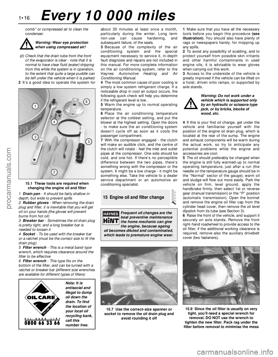
tools before you begin this procedure (see
illustration). You should also have plenty of
rags or newspapers handy, for mopping up
any spills.
2To avoid any possibility of scalding, and to
protect yourself from possible skin irritants
and other harmful contaminants in used
engine oils, it is advisable to wear gloves
when carrying out this work.
3Access to the underside of the vehicle is
greatly improved if the vehicle can be lifted on
a hoist, driven onto ramps, or supported by
axle stands.
Warning: Do not work under a
vehicle which is supported only
by an hydraulic or scissors-type
jack, or by bricks, blocks of
wood, etc.
4If this is your first oil change, get under the
vehicle and familiarise yourself with the
position of the engine oil drain plug, which is
located at the rear of the sump. The engine
and exhaust components will be warm during
the actual work, so try to anticipate any
potential problems while the engine and
accessories are cool.
5The oil should preferably be changed when
the engine is still fully warmed-up to normal
operating temperature, just after a run (the
needle on the temperature gauge should be in
the “Normal” sector of the gauge); warm oil
and sludge will flow out more easily. Park the
vehicle on firm, level ground, apply the
handbrake firmly, then select 1st or reverse
gear (manual transmission) or the “P” position
(automatic transmission). Open the bonnet
and remove the engine oil filler cap from the
cylinder head cover, then remove the oil level
dipstick from its tube (see Section 3).
6Raise the front of the vehicle, and support it
securely on axle stands. Remove the front
right-hand roadwheel to provide access to the
oil filter; if the additional working clearance is
required, remove also the auxiliary drivebelt
cover (two fasteners).
15 Engine oil and filter change
1•16
15.1 These tools are required when
changing the engine oil and filter
1Drain pan- It should be fairly shallow in
depth, but wide to prevent spills
2Rubber gloves- When removing the drain
plug and filter, it is inevitable that you will get
oil on your hands (the gloves will prevent
burns from hot oil)
3Breaker bar- Sometimes the oil drain plug
is pretty tight, and a long breaker bar is
needed to loosen it
4Socket- To be used with the breaker bar
or a ratchet (must be the correct size to fit the
drain plug)
5Filter wrench- This is a metal band-type
wrench, which requires clearance around the
filter to be effective
6Filter wrench- This type fits on the
bottom of the filter, and can be turned with a
ratchet or breaker bar (different size wrenches
are available for different types of filters)
15.7 Use the correct-size spanner or
socket to remove the oil drain plug and
avoid rounding it off15.9 Since the oil filter is usually on very
tight, you’ll need a special wrench for
removal. DO NOT use the wrench to
tighten the new filter. Pack rag under the
filter before removal to minimise the mess
Every 10 000 miles
Frequent oil changes are the
best preventive maintenance
the home mechanic can give
the engine, because ageing
oil becomes diluted and contaminated,
which leads to premature engine wear.
Note: It is
antisocial and
illegal to dump
oil down the
drain. To find
the location of
your local oil
recycling bank,
call this
number free.
procarmanuals.com
Page 31 of 279
Warning: To avoid personal
injury, never get beneath the
vehicle when it is supported by
only by a jack. The jack provided
with your vehicle is designed solely for
raising the vehicle to remove and refit the
roadwheels. Always use axle stands to
support the vehicle when it becomes
necessary to place your body underneath
the vehicle.
7Being careful not to touch the hot exhaust
components, place the drain pan under the
drain plug, and unscrew the plug (see
illustration). If possible, try to keep the plug
pressed into the sump while unscrewing it by
hand the last couple of turns. As the plug
releases from the threads, move it away
sharply, so the stream of oil issuing from the
sump runs into the pan, not up your sleeve!
Allow the oil to drain into the drain pan, and
check the condition of the plug’s sealing
washer; renew it if worn or damaged.
8Allow some time for the old oil to drain,
noting that it may be necessary to reposition
the pan as the oil flow slows to a trickle; when
the oil has completely drained, wipe clean the
drain plug and its threads in the sump and
refit the plug, tightening it to the specified
torque wrench setting.
9Using a suitable filter removal tool, unscrew
the oil filter from the right-hand rear of the
cylinder block; be prepared for some oil
spillage (see illustration). Check the old filter
to make sure that the rubber sealing ring
hasn’t stuck to the engine; if it has, carefully
remove it. Withdraw the filter through the
wheel arch, taking care to spill as little oil as
possible.
10Using a clean, lint-free rag, wipe clean the
cylinder block around the filter mounting. If
there are no specific instructions supplied
with it, fit a new oil filter as follows. Apply a
light coating of clean engine oil to the filter’s
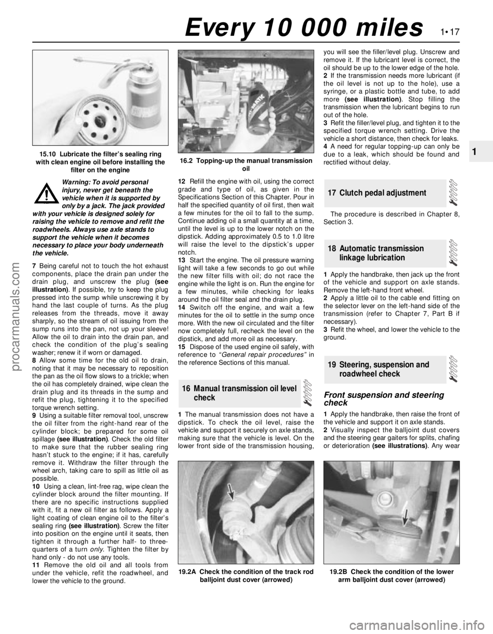
sealing ring (see illustration). Screw the filter
into position on the engine until it seats, then
tighten it through a further half- to three-
quarters of a turn only. Tighten the filter by
hand only - do not use any tools.
11Remove the old oil and all tools from
under the vehicle, refit the roadwheel, and
lower the vehicle to the ground.12Refill the engine with oil, using the correct
grade and type of oil, as given in the
Specifications Section of this Chapter. Pour in
half the specified quantity of oil first, then wait
a few minutes for the oil to fall to the sump.
Continue adding oil a small quantity at a time,
until the level is up to the lower notch on the
dipstick. Adding approximately 0.5 to 1.0 litre
will raise the level to the dipstick’s upper
notch.
13Start the engine. The oil pressure warning
light will take a few seconds to go out while
the new filter fills with oil; do not race the
engine while the light is on. Run the engine for
a few minutes, while checking for leaks
around the oil filter seal and the drain plug.
14Switch off the engine, and wait a few
minutes for the oil to settle in the sump once
more. With the new oil circulated and the filter
now completely full, recheck the level on the
dipstick, and add more oil as necessary.
15Dispose of the used engine oil safely, with
reference to “General repair procedures”in
the reference Sections of this manual.
1The manual transmission does not have a
dipstick. To check the oil level, raise the
vehicle and support it securely on axle stands,
making sure that the vehicle is level. On the
lower front side of the transmission housing,you will see the filler/level plug. Unscrew and
remove it. If the lubricant level is correct, the
oil should be up to the lower edge of the hole.
2If the transmission needs more lubricant (if
the oil level is not up to the hole), use a
syringe, or a plastic bottle and tube, to add
more (see illustration). Stop filling the
transmission when the lubricant begins to run
out of the hole.
3Refit the filler/level plug, and tighten it to the
specified torque wrench setting. Drive the
vehicle a short distance, then check for leaks.
4A need for regular topping-up can only be
due to a leak, which should be found and
rectified without delay.
The procedure is described in Chapter 8,
Section 3.
1Apply the handbrake, then jack up the front
of the vehicle and support on axle stands.
Remove the left-hand front wheel.
2Apply a little oil to the cable end fitting on
the selector lever on the left-hand side of the
transmission (refer to Chapter 7, Part B if
necessary).
3Refit the wheel, and lower the vehicle to the
ground.
Front suspension and steering
check
1Apply the handbrake, then raise the front of
the vehicle and support it on axle stands.
2Visually inspect the balljoint dust covers
and the steering gear gaiters for splits, chafing
or deterioration (see illustrations). Any wear
19 Steering, suspension and
roadwheel check
18 Automatic transmission
linkage lubrication
17 Clutch pedal adjustment
16 Manual transmission oil level
check
1•17
1
19.2B Check the condition of the lower
arm balljoint dust cover (arrowed)
15.10 Lubricate the filter’s sealing ring
with clean engine oil before installing the
filter on the engine16.2 Topping-up the manual transmission
oil
19.2A Check the condition of the track rod
balljoint dust cover (arrowed)
Every 10 000 miles
procarmanuals.com
Page 33 of 279
evidence of leaks, severe corrosion, or
damage. Make sure that all brackets and
rubber mountings are in good condition, and
tight; if any of the mountings are to be
renewed, ensure that the replacements are of
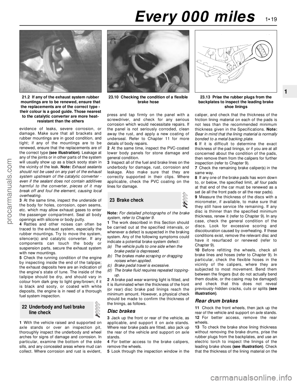
the correct type (see illustration). Leakage at
any of the joints or in other parts of the system
will usually show up as a black sooty stain in
the vicinity of the leak. Note:Exhaust sealants
should not be used on any part of the exhaust
system upstream of the catalytic converter -
even if the sealant does not contain additives
harmful to the converter, pieces of it may
break off and foul the element, causing local
overheating.
3At the same time, inspect the underside of
the body for holes, corrosion, open seams,
etc. which may allow exhaust gases to enter
the passenger compartment. Seal all body
openings with silicone or body putty.
4Rattles and other noises can often be
traced to the exhaust system, especially the
rubber mountings. Try to move the system,
silencer(s) and catalytic converter. If any
components can touch the body or
suspension parts, secure the exhaust system
with new mountings.
5Check the running condition of the engine
by inspecting inside the end of the tailpipe;
the exhaust deposits here are an indication of
the engine’s state of tune. The inside of the
tailpipe should be dry, and should vary in
colour from dark grey to light grey/brown; if it
is black and sooty, or coated with white
deposits, the engine is in need of a thorough
fuel system inspection.
1With the vehicle raised and supported on
axle stands or over an inspection pit,
thoroughly inspect the underbody and wheel
arches for signs of damage and corrosion. In
particular, examine the bottom of the side
sills, and any concealed areas where mud can
collect. Where corrosion and rust is evident,press and tap firmly on the panel with a
screwdriver, and check for any serious
corrosion which would necessitate repairs. If
the panel is not seriously corroded, clean
away the rust, and apply a new coating of
underseal. Refer to Chapter 11 for more
details of body repairs.
2At the same time, inspect the PVC-coated
lower body panels for stone damage and
general condition.
3Inspect all of the fuel and brake lines on the
underbody for damage, rust, corrosion and
leakage. Also make sure that they are
correctly supported in their clips. Where
applicable, check the PVC coating on the
lines for damage.
Note:For detailed photographs of the brake
system, refer to Chapter 9.
1The work described in this Section should
be carried out at the specified intervals, or
whenever a defect is suspected in the braking
system. Any of the following symptoms could
indicate a potential brake system defect:
(a) The vehicle pulls to one side when the
brake pedal is depressed.
(b) The brakes make scraping or dragging
noises when applied.
(c) Brake pedal travel is excessive.
(d) The brake fluid requires repeated topping-
up.
2A brake pad wear warning light is fitted, and
it is illuminated when the thickness of the front
(or rear) disc brake pad linings reach the
minimum amount. However, a physical check
should be made to confirm the thickness of
the linings, as follows.
Disc brakes
3Jack up the front or rear of the vehicle, as
applicable, and support it on axle stands.
Where rear brake pads are fitted, also jack up
the rear of the vehicle and support on axle
stands.
4For better access to the brake calipers,
remove the wheels.
5Look through the inspection window in thecaliper, and check that the thickness of the
friction lining material on each of the pads is
not less than the recommended minimum
thickness given in the Specifications. Note:
Bear in mind that the lining material is normally
bonded to a metal backing plate.
6If it is difficult to determine the exact
thickness of the pad linings, or if you are at all
concerned about the condition of the pads,
then remove them from the calipers for further
inspection (refer to Chapter 9).
7Check the remaining brake caliper(s) in the
same way.
8If any one of the brake pads has worn down
to, or below, the specified limit, all fourpads
at that end of the car must be renewed as a
set (ie all the front pads or all the rear pads).
9Measure the thickness of the discs with a
micrometer, if available, to make sure that
they still have service life remaining. If any
disc is thinner than the specified minimum
thickness, renew it (refer to Chapter 9). In any
case, check the general condition of the
discs. Look for excessive scoring and
discolouration caused by overheating. If these
conditions exist, remove the relevant disc and
have it resurfaced or renewed (refer to
Chapter 9).
10Before refitting the wheels, check all
brake lines and hoses (refer to Chapter 9). In
particular, check the flexible hoses in the
vicinity of the calipers, where they are
subjected to most movement. Bend them
between the fingers (but do not actually bend
them double, or the casing may be damaged)
and check that this does not reveal
previously-hidden cracks, cuts or splits (see
illustration).
Rear drum brakes
11Chock the front wheels, then jack up the
rear of the vehicle and support on axle stands.
12For better access, remove the rear
wheels.
13To check the brake shoe lining thickness
without removing the brake drums, prise the
rubber plugs from the backplates, and use an
electric torch to inspect the linings of the
leading brake shoes (see illustration). Check
that the thickness of the lining material on the
23 Brake check
22 Underbody and fuel/brake
line check
1•19
121.2 If any of the exhaust system rubber
mountings are to be renewed, ensure that
the replacements are of the correct type -
their colour is a good guide. Those nearest
to the catalytic converter are more heat-
resistant than the others23.10 Checking the condition of a flexible
brake hose23.13 Prise the rubber plugs from the
backplates to inspect the leading brake
shoe linings
Every 000 miles
procarmanuals.com
Page 35 of 279
pleated-paper type filter, it cannot be washed
or re-oiled. If it cannot be cleaned
satisfactorily with compressed air, discard
and renew it.
Warning: Wear eye protection
when using compressed air!
8Refitting is the reverse of the removal
procedure; ensure that the element and
housing are securely seated, so that unfiltered
air cannot enter the passenger compartment.
Note:If the antifreeze used is Ford’s own, or of
similar quality, the coolant need not be
renewed for the life of the vehicle. If the
vehicle’s history is unknown, if antifreeze of
lesser quality is known to be in the system, or
simply if you prefer to follow conventional
servicing intervals, the coolant should be
changed periodically (typically, every 2 years)
as described here. Refer also to the
information in Section 2 of this Chapter.
Warning: Do not allow antifreeze
to come in contact with your skin
or painted surfaces of the
vehicle. Flush contaminated areas
immediately with plenty of water. Don’t
store new coolant, or leave old coolant
lying around, where it’s accessible to
children or pets - they’re attracted by its
sweet smell. Ingestion of even a small
amount of coolant can be fatal! Wipe up
garage-floor and drip-pan spills
immediately. Keep antifreeze containers
covered, and repair cooling system leaks
as soon as they’re noticed.
Warning: Never remove the
expansion tank filler cap when
the engine is running, or has just
been switched off, as the cooling system
will be hot, and the consequent escaping
steam and scalding coolant could cause
serious injury.
Coolant draining
Warning: Wait until the engine is
cold before starting this
procedure.1To drain the system, first remove the
expansion tank filler cap (see Section 3).
2If the additional working clearance is
required, raise the front of the vehicle and
support it securely on axle stands.
3Remove the radiator undershield (eight or
nine screws), then place a large drain tray
underneath, and unscrew the radiator drain
plug; direct as much of the escaping coolant
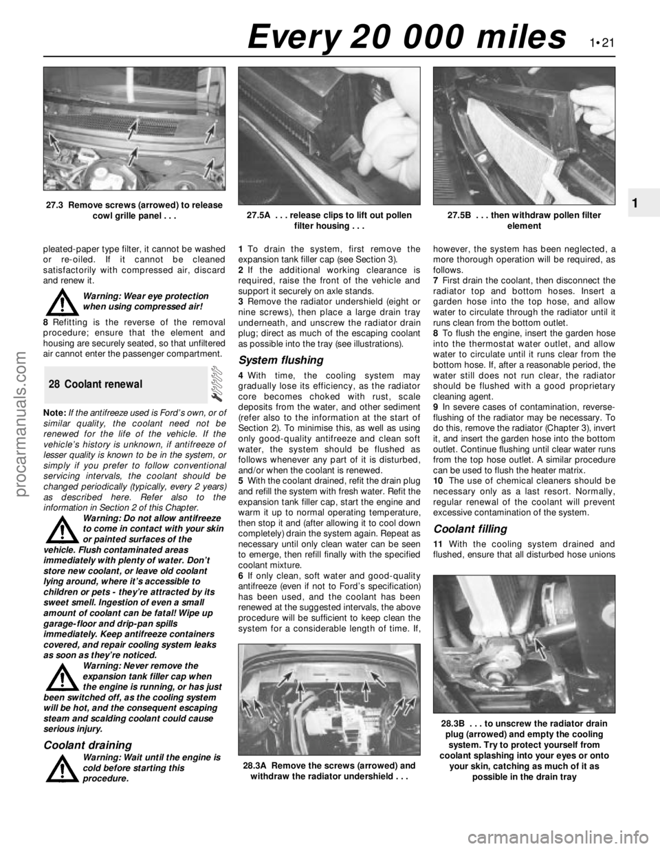
as possible into the tray (see illustrations).
System flushing
4With time, the cooling system may
gradually lose its efficiency, as the radiator
core becomes choked with rust, scale
deposits from the water, and other sediment
(refer also to the information at the start of
Section 2). To minimise this, as well as using
only good-quality antifreeze and clean soft
water, the system should be flushed as
follows whenever any part of it is disturbed,
and/or when the coolant is renewed.
5With the coolant drained, refit the drain plug
and refill the system with fresh water. Refit the
expansion tank filler cap, start the engine and
warm it up to normal operating temperature,
then stop it and (after allowing it to cool down
completely) drain the system again. Repeat as
necessary until only clean water can be seen
to emerge, then refill finally with the specified
coolant mixture.
6If only clean, soft water and good-quality
antifreeze (even if not to Ford’s specification)
has been used, and the coolant has been
renewed at the suggested intervals, the above
procedure will be sufficient to keep clean the
system for a considerable length of time. If,however, the system has been neglected, a
more thorough operation will be required, as
follows.
7First drain the coolant, then disconnect the
radiator top and bottom hoses. Insert a
garden hose into the top hose, and allow
water to circulate through the radiator until it
runs clean from the bottom outlet.
8To flush the engine, insert the garden hose
into the thermostat water outlet, and allow
water to circulate until it runs clear from the
bottom hose. If, after a reasonable period, the
water still does not run clear, the radiator
should be flushed with a good proprietary
cleaning agent.
9In severe cases of contamination, reverse-
flushing of the radiator may be necessary. To
do this, remove the radiator (Chapter 3), invert
it, and insert the garden hose into the bottom
outlet. Continue flushing until clear water runs
from the top hose outlet. A similar procedure
can be used to flush the heater matrix.
10The use of chemical cleaners should be
necessary only as a last resort. Normally,
regular renewal of the coolant will prevent
excessive contamination of the system.
Coolant filling
11With the cooling system drained and
flushed, ensure that all disturbed hose unions
28 Coolant renewal
1•21
1
28.3A Remove the screws (arrowed) and
withdraw the radiator undershield . . .
28.3B . . . to unscrew the radiator drain
plug (arrowed) and empty the cooling
system. Try to protect yourself from
coolant splashing into your eyes or onto
your skin, catching as much of it as
possible in the drain tray
27.3 Remove screws (arrowed) to release
cowl grille panel . . .27.5A . . . release clips to lift out pollen
filter housing . . .27.5B . . . then withdraw pollen filter
element
Every 20 000 miles
procarmanuals.com
Page 36 of 279
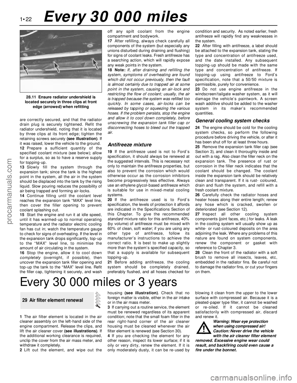
are correctly secured, and that the radiator
drain plug is securely tightened. Refit the
radiator undershield, noting that it is located
by three clips at its front edge; tighten the
retaining screws securely (see illustration). If
it was raised, lower the vehicle to the ground.
12Prepare a sufficient quantity of the
specified coolant mixture (see below); allow
for a surplus, so as to have a reserve supply
for topping-up.
13Slowly fill the system through the
expansion tank; since the tank is the highest
point in the system, all the air in the system
should be displaced into the tank by the rising
liquid. Slow pouring reduces the possibility of
air being trapped and forming air-locks.
14Continue filling until the coolant level
reaches the expansion tank “MAX” level line,
then cover the filler opening to prevent
coolant splashing out.
15Start the engine and run it at idle speed,
until it has warmed-up to normal operating
temperature and the radiator electric cooling
fan has cut in; watch the temperature gauge
to check for signs of overheating. If the level in
the expansion tank drops significantly, top-up
to the “MAX” level line, to minimise the
amount of air circulating in the system.
16Stop the engine, allow it to cool down
completely(overnight, if possible), then
uncover the expansion tank filler opening and
top-up the tank to the “MAX” level line. Refit
the filler cap, tightening it securely, and washoff any spilt coolant from the engine
compartment and bodywork.
17After refilling, always check carefully all
components of the system (but especially any
unions disturbed during draining and flushing)
for signs of coolant leaks. Fresh antifreeze has
a searching action, which will rapidly expose
any weak points in the system.
18 Note:If, after draining and refilling the
system, symptoms of overheating are found
which did not occur previously, then the fault
is almost certainly due to trapped air at some
point in the system, causing an air-lock and
restricting the flow of coolant; usually, the air
is trapped because the system was refilled too
quickly. In some cases, air-locks can be
released by tapping or squeezing the various
hoses. If the problem persists, stop the engine
and allow it to cool down completely, before
unscrewing the expansion tank filler cap or
disconnecting hoses to bleed out the trapped
air.
Antifreeze mixture
19If the antifreeze used is not to Ford’s
specification, it should always be renewed at
the suggested intervals. This is necessary not
only to maintain the antifreeze properties, but
also to prevent the corrosion which would
otherwise occur as the corrosion inhibitors
become progressively less effective. Always
use an ethylene glycol-based antifreeze which
is suitable for use in mixed-metal cooling
systems.
20If the antifreeze used is to Ford’s
specification, the levels of protection it affords
are indicated in the Specifications Section of
this Chapter. To give the recommended
standardmixture ratio for this antifreeze, 40%
(by volume) of antifreeze must be mixed with
60% of clean, soft water; if you are using any
other type of antifreeze, follow its
manufacturer’s instructions to achieve the
correct ratio. It is best to make up slightly
more than the system’s specified capacity, so
that a supply is available for subsequent
topping-up.
21Before adding antifreeze, the cooling
system should be completely drained,
preferably flushed, and all hoses checked forcondition and security. As noted earlier, fresh
antifreeze will rapidly find any weaknesses in
the system.
22After filling with antifreeze, a label should
be attached to the expansion tank, stating the
type and concentration of antifreeze used,
and the date installed. Any subsequent
topping-up should be made with the same
type and concentration of antifreeze. If
topping-up using antifreeze to Ford’s
specification, note that a 50/50 mixture is
permissible, purely for convenience.
23Do not use engine antifreeze in the
windscreen/tailgate washer system, as it will
damage the vehicle’s paintwork. A screen
wash additive should be added to the washer
system in its maker’s recommended
quantities.
General cooling system checks
24The engine should be cold for the cooling
system checks, so perform the following
procedure before driving the vehicle, or after it
has been shut off for at least three hours.
25Remove the expansion tank filler cap (see
Section 3), and clean it thoroughly inside and
out with a rag. Also clean the filler neck on the
expansion tank. The presence of rust or
corrosion in the filler neck indicates that the
coolant should be changed. The coolant
inside the expansion tank should be relatively
clean and transparent. If it is rust- coloured,
drain and flush the system, and refill with a
fresh coolant mixture.
26Carefully check the radiator hoses and
heater hoses along their entire length; renew
any hose which is cracked, swollen or
deteriorated (see Section 12).
27Inspect all other cooling system
components (joint faces, etc.) for leaks. A leak
in the cooling system will usually show up as
white- or rust-coloured deposits on the area
adjoining the leak. Where any problems of this
nature are found on system components,
renew the component or gasket with
reference to Chapter 3.
28Clean the front of the radiator with a soft
brush to remove all insects, leaves, etc,
embedded in the radiator fins. Be careful not
to damage the radiator fins, or cut your fingers
on them.
1•22
28.11 Ensure radiator undershield is
located securely in three clips at front
edge (arrowed) when refitting
Every 30 000 miles
Every 30 000 miles or 3 years
1The air filter element is located in the air
cleaner assembly on the left-hand side of the
engine compartment. Release the clips, and
lift the air cleaner cover (see illustrations). If
the additional working clearance is required,
unclip the cover from the air mass meter, and
withdraw it completely.
2Lift out the element, and wipe out thehousing (see illustration). Check that no
foreign matter is visible, either in the air intake
or in the air mass meter.
3If carrying out a routine service, the element
must be renewed regardless of its apparent
condition; note that the small foam filter in the
rear right-hand corner of the air cleaner
housing must be cleaned whenever the air
filter element is renewed (see Section 30).
4If you are checking the element for any
other reason, inspect its lower surface; if it is
oily or very dirty, renew the element. If it is
only moderately dusty, it can be re-used byblowing it clean from the upper to the lower
surface with compressed air. Because it is a
pleated-paper type filter, it cannot be washed
or re-oiled. If it cannot be cleaned
satisfactorily with compressed air, discard
and renew it.
Warning: Wear eye protection
when using compressed air!
Caution: Never drive the vehicle
with the air cleaner filter element
removed. Excessive engine wear could
result, and backfiring could even cause a
fire under the bonnet.
29 Air filter element renewal
procarmanuals.com
Page 38 of 279

To prevent the possibility of mixing up spark
plug (HT) leads, it is a good idea to try to work
on one spark plug at a time.
4If the marks on the original-equipment
spark plug (HT) leads cannot be seen, mark
the leads 1 to 4, to correspond to the cylinder
the lead serves (No 1 cylinder is at the timing
belt end of the engine). Pull the leads from the
plugs by gripping the rubber boot sealing thecylinder head cover opening, not the lead,
otherwise the lead connection may be
fractured.
5It is advisable to soak up any water in the
spark plug recesses with a rag, and to remove
any dirt from them using a clean brush,
vacuum cleaner or compressed air before
removing the plugs, to prevent any dirt or
water from dropping into the cylinders. Warning: Wear eye protection
when using compressed air!
6Unscrew the spark plugs, ensuring that the
socket is kept in alignment with each plug - if
the socket is forcibly moved to either side, the
porcelain top of the plug may be broken off. If
any undue difficulty is encountered when
unscrewing any of the spark plugs, carefully
1•24Every 30 000 miles
Specifications
Engine
Direction of crankshaft rotation . . . . . . . . . . . . . . . . . . . . . . . . . . . . . . . . Clockwise (seen from right-hand side of vehicle)
Oil filter . . . . . . . . . . . . . . . . . . . . . . . . . . . . . . . . . . . . . . . . . . . . . . . . . . Champion C148
Cooling system
Coolant protection at 40% antifreeze/water mixture ratio:
Slush point . . . . . . . . . . . . . . . . . . . . . . . . . . . . . . . . . . . . . . . . . . . . . -25°C (-13°F)
Solidifying point . . . . . . . . . . . . . . . . . . . . . . . . . . . . . . . . . . . . . . . . . . -30°C (-22°F)
Coolant specific gravity at 40% antifreeze/water mixture ratio and
15°C/59°F - with no other additives in coolant . . . . . . . . . . . . . . . . . . . . 1.061
Fuel system
Idle speed - nominal . . . . . . . . . . . . . . . . . . . . . . . . . . . . . . . . . . . . . . . . 830 ± 50 rpm*
Air filter element . . . . . . . . . . . . . . . . . . . . . . . . . . . . . . . . . . . . . . . . . . . Champion U618
Fuel filter . . . . . . . . . . . . . . . . . . . . . . . . . . . . . . . . . . . . . . . . . . . . . . . . . Champion L218
* Note: Given for reference only - not adjustable.
Ignition system
Firing order . . . . . . . . . . . . . . . . . . . . . . . . . . . . . . . . . . . . . . . . . . . . . . . 1-3-4-2 (No 1 cylinder at timing belt end of engine)
Spark plugs:*
Type . . . . . . . . . . . . . . . . . . . . . . . . . . . . . . . . . . . . . . . . . . . . . . . . . . . Champion RE7YCC
Electrode gap . . . . . . . . . . . . . . . . . . . . . . . . . . . . . . . . . . . . . . . . . . . 1.0 mm
Spark plug (HT) leads:
Type . . . . . . . . . . . . . . . . . . . . . . . . . . . . . . . . . . . . . . . . . . . . . . . . . . . Champion type not available
Maximum resistance per lead . . . . . . . . . . . . . . . . . . . . . . . . . . . . . . . 30 000 ohms
* Information on spark plug types and electrode gaps is as recommended by Champion Spark Plug. Where alternative types are used, refer to
their manufacturer’s recommendations
Braking system
Note: No minimum lining thicknesses are given by Ford - the following is given as a general recommendation. If the pad wear warning light
comes on before the front brake pad linings reach the minimum thickness, the pads should nevertheless be renewed immediately.
Minimum front or rear brake pad lining thickness . . . . . . . . . . . . . . . . . 1.5 mm
Minimum rear brake shoe lining thickness . . . . . . . . . . . . . . . . . . . . . . . 1.0 mm
Suspension and steering
Tyre pressures (cold):Front Rear
Normally laden* . . . . . . . . . . . . . . . . . . . . . . . . . . . . . . . . . . . . . . . . . 2.1 bars (31 psi) 2.1 bars (31 psi)
Fully laden* . . . . . . . . . . . . . . . . . . . . . . . . . . . . . . . . . . . . . . . . . . . . . 2.4 bars (35 psi) 2.8 bars (41 psi)
Note: Normally laden means up to 3 persons. For sustained high speeds above 100 mph (160 km/h), increased pressures are necessary.
Consult the driver’s handbook supplied with the vehicle.
Wiper blades
Windscreen:
Driver’s side . . . . . . . . . . . . . . . . . . . . . . . . . . . . . . . . . . . . . . . . . . . . . Champion X 5303 (and SP 01 spoiler)
Passenger’s side . . . . . . . . . . . . . . . . . . . . . . . . . . . . . . . . . . . . . . . . . Champion X 5103
Tailgate:
Hatchback . . . . . . . . . . . . . . . . . . . . . . . . . . . . . . . . . . . . . . . . . . . . . . Champion X 5103
Estate . . . . . . . . . . . . . . . . . . . . . . . . . . . . . . . . . . . . . . . . . . . . . . . . . Champion type not available
Torque wrench settingsNm lbf ft
Auxiliary drivebelt cover fasteners . . . . . . . . . . . . . . . . . . . . . . . . . . . . . 5 to 10 4 to 7
Auxiliary drivebelt automatic tensioner Torx screws . . . . . . . . . . . . . . . . 23 17
Engine oil drain plug . . . . . . . . . . . . . . . . . . . . . . . . . . . . . . . . . . . . . . . . 25 18
Manual transmission filler/level plug . . . . . . . . . . . . . . . . . . . . . . . . . . . . 35 26
Radiator undershield screws . . . . . . . . . . . . . . . . . . . . . . . . . . . . . . . . . . 7 5
Spark plugs . . . . . . . . . . . . . . . . . . . . . . . . . . . . . . . . . . . . . . . . . . . . . . . 15 11
procarmanuals.com
Page 40 of 279
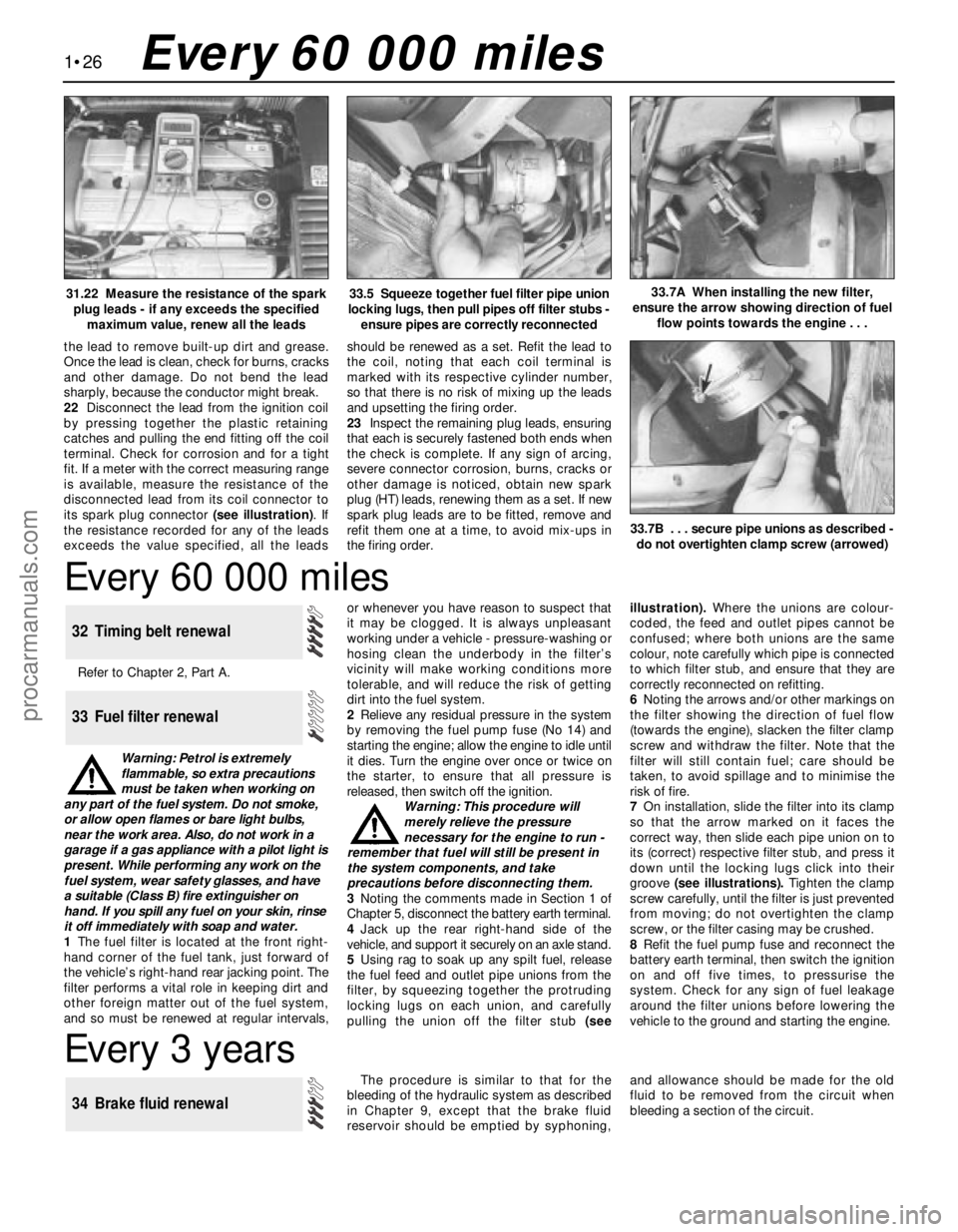
1•26Every 60 000 miles
Every 60 000 miles
Refer to Chapter 2, Part A.
Warning: Petrol is extremely
flammable, so extra precautions
must be taken when working on
any part of the fuel system. Do not smoke,
or allow open flames or bare light bulbs,
near the work area. Also, do not work in a
garage if a gas appliance with a pilot light is
present. While performing any work on the
fuel system, wear safety glasses, and have
a suitable (Class B) fire extinguisher on
hand. If you spill any fuel on your skin, rinse
it off immediately with soap and water.
1The fuel filter is located at the front right-
hand corner of the fuel tank, just forward of
the vehicle’s right-hand rear jacking point. The
filter performs a vital role in keeping dirt and
other foreign matter out of the fuel system,
and so must be renewed at regular intervals,or whenever you have reason to suspect that
it may be clogged. It is always unpleasant
working under a vehicle - pressure-washing or
hosing clean the underbody in the filter’s
vicinity will make working conditions more
tolerable, and will reduce the risk of getting
dirt into the fuel system.
2Relieve any residual pressure in the system
by removing the fuel pump fuse (No 14) and
starting the engine; allow the engine to idle until
it dies. Turn the engine over once or twice on
the starter, to ensure that all pressure is
released, then switch off the ignition.
Warning: This procedure will
merely relieve the pressure
necessary for the engine to run -
remember that fuel will still be present in
the system components, and take
precautions before disconnecting them.
3Noting the comments made in Section 1 of
Chapter 5, disconnect the battery earth terminal.
4Jack up the rear right-hand side of the
vehicle, and support it securely on an axle stand.
5Using rag to soak up any spilt fuel, release
the fuel feed and outlet pipe unions from the
filter, by squeezing together the protruding
locking lugs on each union, and carefully
pulling the union off the filter stub (seeillustration). Where the unions are colour-
coded, the feed and outlet pipes cannot be
confused; where both unions are the same
colour, note carefully which pipe is connected
to which filter stub, and ensure that they are
correctly reconnected on refitting.
6Noting the arrows and/or other markings on
the filter showing the direction of fuel flow
(towards the engine), slacken the filter clamp
screw and withdraw the filter. Note that the
filter will still contain fuel; care should be
taken, to avoid spillage and to minimise the
risk of fire.
7On installation, slide the filter into its clamp
so that the arrow marked on it faces the
correct way, then slide each pipe union on to
its (correct) respective filter stub, and press it
down until the locking lugs click into their
groove (see illustrations). Tighten the clamp
screw carefully, until the filter is just prevented
from moving; do not overtighten the clamp
screw, or the filter casing may be crushed.
8Refit the fuel pump fuse and reconnect the
battery earth terminal, then switch the ignition
on and off five times, to pressurise the
system. Check for any sign of fuel leakage
around the filter unions before lowering the
vehicle to the ground and starting the engine.
33 Fuel filter renewal
32 Timing belt renewal
33.5 Squeeze together fuel filter pipe union
locking lugs, then pull pipes off filter stubs -
ensure pipes are correctly reconnected33.7A When installing the new filter,
ensure the arrow showing direction of fuel
flow points towards the engine . . .
Every 3 years
The procedure is similar to that for the
bleeding of the hydraulic system as described
in Chapter 9, except that the brake fluid
reservoir should be emptied by syphoning,and allowance should be made for the old
fluid to be removed from the circuit when
bleeding a section of the circuit.
34 Brake fluid renewal
31.22 Measure the resistance of the spark
plug leads - if any exceeds the specified
maximum value, renew all the leads
the lead to remove built-up dirt and grease.
Once the lead is clean, check for burns, cracks
and other damage. Do not bend the lead
sharply, because the conductor might break.
22Disconnect the lead from the ignition coil
by pressing together the plastic retaining
catches and pulling the end fitting off the coil
terminal. Check for corrosion and for a tight
fit. If a meter with the correct measuring range
is available, measure the resistance of the
disconnected lead from its coil connector to
its spark plug connector (see illustration). If
the resistance recorded for any of the leads
exceeds the value specified, all the leadsshould be renewed as a set. Refit the lead to
the coil, noting that each coil terminal is
marked with its respective cylinder number,
so that there is no risk of mixing up the leads
and upsetting the firing order.
23Inspect the remaining plug leads, ensuring
that each is securely fastened both ends when
the check is complete. If any sign of arcing,
severe connector corrosion, burns, cracks or
other damage is noticed, obtain new spark
plug (HT) leads, renewing them as a set. If new
spark plug leads are to be fitted, remove and
refit them one at a time, to avoid mix-ups in
the firing order.
33.7B . . . secure pipe unions as described -
do not overtighten clamp screw (arrowed)
procarmanuals.com
Page 41 of 279
Chapter 2 Part A:
In-car engine repair procedures
Auxiliary drivebelt check and renewal . . . . . . . . . . . . . See Chapter 1
Camshaft oil seals - renewal . . . . . . . . . . . . . . . . . . . . . . . . . . . . . . . 12
Camshafts and hydraulic tappets - removal, inspection
and refitting . . . . . . . . . . . . . . . . . . . . . . . . . . . . . . . . . . . . . . . . . . 13
Compression test - description and interpretation . . . . . . . . . . . . . . 3
Crankshaft oil seals - renewal . . . . . . . . . . . . . . . . . . . . . . . . . . . . . . 20
Crankshaft pulley - removal and refitting . . . . . . . . . . . . . . . . . . . . . 8
Cylinder head - removal and refitting . . . . . . . . . . . . . . . . . . . . . . . . 14
Cylinder head and valve components - cleaning and
inspection . . . . . . . . . . . . . . . . . . . . . . . . . . . . . . . . . . . See Chapter 2B
Cylinder head cover - removal and refitting . . . . . . . . . . . . . . . . . . . 5
Engine oil and filter change . . . . . . . . . . . . . . . . . . . . . See Chapter 1
Engine oil level check . . . . . . . . . . . . . . . . . . . . . . . . . . See Chapter 1
Engine overhaul - general information . . . . . . . . . . . . . See Chapter 2B
Engine/transmission - removal and refitting . . . . . . . . See Chapter 2B
Engine/transmission mountings - inspection and renewal . . . . . . . . 22
Exhaust manifold - removal, inspection and refitting . . . . . . . . . . . . 7Flywheel/driveplate - removal, inspection and refitting . . . . . . . . . . 21
General information . . . . . . . . . . . . . . . . . . . . . . . . . . . . . . . . . . . . . . 1
Inlet manifold - removal and refitting . . . . . . . . . . . . . . . . . . . . . . . . 6
Oil cooler - removal and refitting . . . . . . . . . . . . . . . . . . . . . . . . . . . . 17
Oil level sensor - removal and refitting . . . . . . . . . . . . . . . . . . . . . . . 18
Oil pressure warning light switch - removal and refitting . . . . . . . . . 19
Oil pump - removal, inspection and refitting . . . . . . . . . . . . . . . . . . . 16
Repair operations possible with the engine in the vehicle . . . . . . . . 2
Spark plug renewal . . . . . . . . . . . . . . . . . . . . . . . . . . . See Chapter 1
Sump - removal and refitting . . . . . . . . . . . . . . . . . . . . . . . . . . . . . . . 15
Timing belt - removal, refitting and adjustment . . . . . . . . . . . . . . . . 10
Timing belt covers - removal and refitting . . . . . . . . . . . . . . . . . . . . . 9
Timing belt tensioner and toothed pulleys - removal,
inspection and refitting . . . . . . . . . . . . . . . . . . . . . . . . . . . . . . . . . 11
Top Dead Centre (TDC) for No 1 piston - locating . . . . . . . . . . . . . . 4
Water pump - removal and refitting . . . . . . . . . . . . . . . See Chapter 3
General
Engine type . . . . . . . . . . . . . . . . . . . . . . . . . . . . . . . . . . . . . . . . . . . . . . . Four-cylinder, in-line, double overhead camshafts
Engine code:
1.6 litre models . . . . . . . . . . . . . . . . . . . . . . . . . . . . . . . . . . . . . . . . . . LIF
1.8 litre models . . . . . . . . . . . . . . . . . . . . . . . . . . . . . . . . . . . . . . . . . . RKA
2.0 litre models . . . . . . . . . . . . . . . . . . . . . . . . . . . . . . . . . . . . . . . . . . NGA
Capacity:
1.6 litre models . . . . . . . . . . . . . . . . . . . . . . . . . . . . . . . . . . . . . . . . . . 1597 cc
1.8 litre models . . . . . . . . . . . . . . . . . . . . . . . . . . . . . . . . . . . . . . . . . . 1796 cc
2.0 litre models . . . . . . . . . . . . . . . . . . . . . . . . . . . . . . . . . . . . . . . . . . 1988 cc
Bore:
1.6 litre models . . . . . . . . . . . . . . . . . . . . . . . . . . . . . . . . . . . . . . . . . . 76.0 mm
1.8 litre models . . . . . . . . . . . . . . . . . . . . . . . . . . . . . . . . . . . . . . . . . . 80.6 mm
2.0 litre models . . . . . . . . . . . . . . . . . . . . . . . . . . . . . . . . . . . . . . . . . . 84.8 mm
Stroke - all models . . . . . . . . . . . . . . . . . . . . . . . . . . . . . . . . . . . . . . . . . 88.0 mm
Compression ratio:
1.6 litre models . . . . . . . . . . . . . . . . . . . . . . . . . . . . . . . . . . . . . . . . . . 10.3:1
1.8 and 2.0 litre models . . . . . . . . . . . . . . . . . . . . . . . . . . . . . . . . . . . . 10.0:1
Compression pressure - at starter motor speed, engine fully warmed-up .Not available
Firing order . . . . . . . . . . . . . . . . . . . . . . . . . . . . . . . . . . . . . . . . . . . . . . . 1-3-4-2 (No 1 cylinder at timing belt end)
Direction of crankshaft rotation . . . . . . . . . . . . . . . . . . . . . . . . . . . . . . . . Clockwise (seen from right-hand side of vehicle)
Cylinder head
Hydraulic tappet bore inside diameter . . . . . . . . . . . . . . . . . . . . . . . . . . 28.395 to 28.425 mm
Camshafts and hydraulic tappets
Camshaft bearing journal diameter . . . . . . . . . . . . . . . . . . . . . . . . . . . . . 25.960 to 25.980 mm
Camshaft bearing journal-to-cylinder head running clearance . . . . . . . . 0.020 to 0.070 mm
Camshaft endfloat . . . . . . . . . . . . . . . . . . . . . . . . . . . . . . . . . . . . . . . . . . 0.080 to 0.220 mm
Hydraulic tappet diameter . . . . . . . . . . . . . . . . . . . . . . . . . . . . . . . . . . . . 28.400 mm
2A•1
Easy,suitable for
novice with little
experienceFairly easy,suitable
for beginner with
some experienceFairly difficult,suitable
for competent DIY
mechanicDifficult,suitable for
experienced DIY
mechanicVery difficult,
suitable for expert DIY
or professional
Degrees of difficulty
Specifications Contents2A
procarmanuals.com