1993 FORD MONDEO warning
[x] Cancel search: warningPage 42 of 279
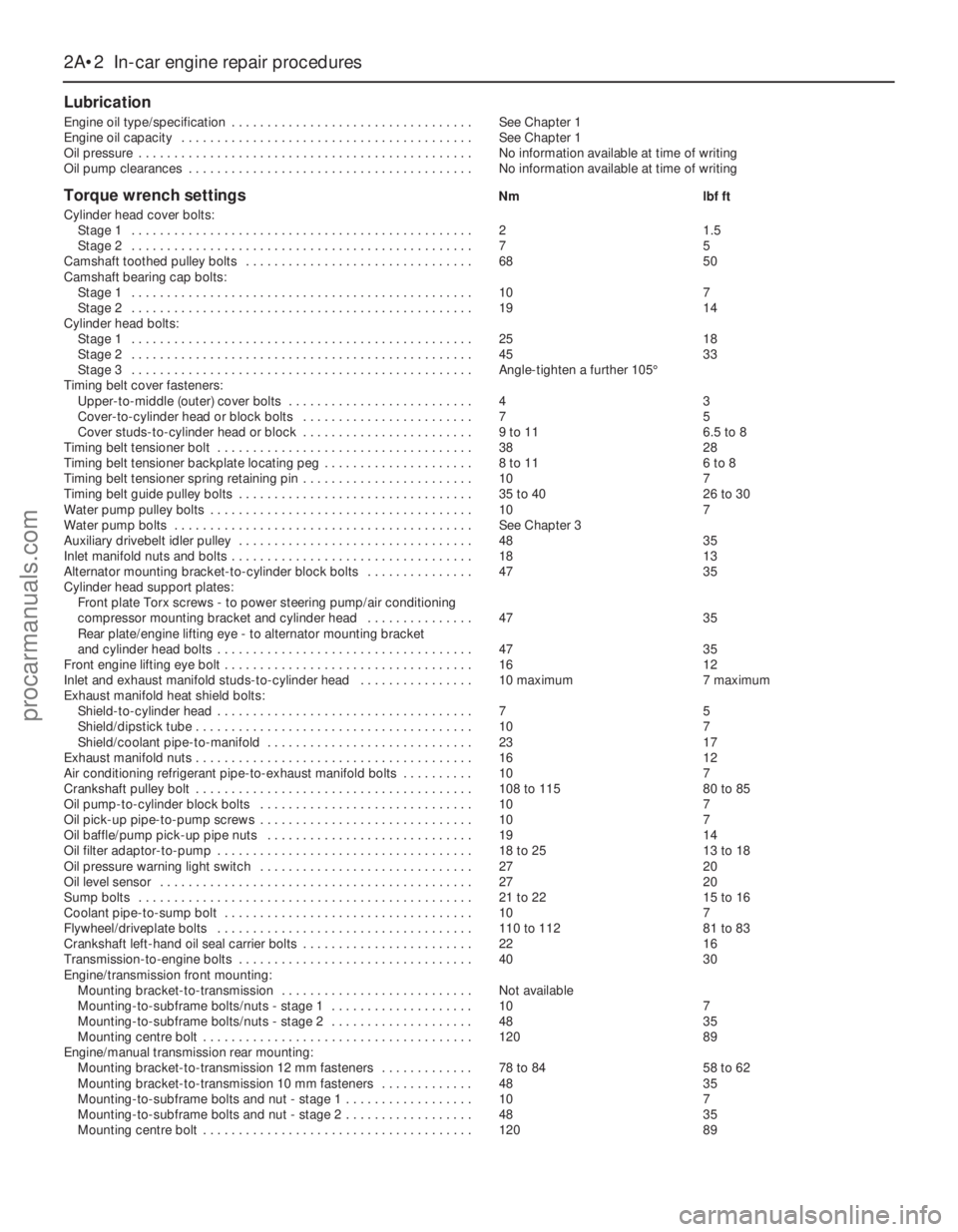
Lubrication
Engine oil type/specification . . . . . . . . . . . . . . . . . . . . . . . . . . . . . . . . . . See Chapter 1
Engine oil capacity . . . . . . . . . . . . . . . . . . . . . . . . . . . . . . . . . . . . . . . . . See Chapter 1
Oil pressure . . . . . . . . . . . . . . . . . . . . . . . . . . . . . . . . . . . . . . . . . . . . . . . No information available at time of writing
Oil pump clearances . . . . . . . . . . . . . . . . . . . . . . . . . . . . . . . . . . . . . . . . No information available at time of writing
Torque wrench settingsNm lbf ft
Cylinder head cover bolts:
Stage 1 . . . . . . . . . . . . . . . . . . . . . . . . . . . . . . . . . . . . . . . . . . . . . . . . 2 1.5
Stage 2 . . . . . . . . . . . . . . . . . . . . . . . . . . . . . . . . . . . . . . . . . . . . . . . . 7 5
Camshaft toothed pulley bolts . . . . . . . . . . . . . . . . . . . . . . . . . . . . . . . . 68 50
Camshaft bearing cap bolts:
Stage 1 . . . . . . . . . . . . . . . . . . . . . . . . . . . . . . . . . . . . . . . . . . . . . . . . 10 7
Stage 2 . . . . . . . . . . . . . . . . . . . . . . . . . . . . . . . . . . . . . . . . . . . . . . . . 19 14
Cylinder head bolts:
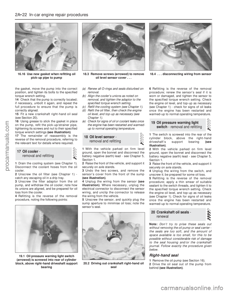
Stage 1 . . . . . . . . . . . . . . . . . . . . . . . . . . . . . . . . . . . . . . . . . . . . . . . . 25 18
Stage 2 . . . . . . . . . . . . . . . . . . . . . . . . . . . . . . . . . . . . . . . . . . . . . . . . 45 33
Stage 3 . . . . . . . . . . . . . . . . . . . . . . . . . . . . . . . . . . . . . . . . . . . . . . . . Angle-tighten a further 105°
Timing belt cover fasteners:
Upper-to-middle (outer) cover bolts . . . . . . . . . . . . . . . . . . . . . . . . . . 4 3
Cover-to-cylinder head or block bolts . . . . . . . . . . . . . . . . . . . . . . . . 7 5
Cover studs-to-cylinder head or block . . . . . . . . . . . . . . . . . . . . . . . . 9 to 11 6.5 to 8
Timing belt tensioner bolt . . . . . . . . . . . . . . . . . . . . . . . . . . . . . . . . . . . . 38 28
Timing belt tensioner backplate locating peg . . . . . . . . . . . . . . . . . . . . . 8 to 11 6 to 8
Timing belt tensioner spring retaining pin . . . . . . . . . . . . . . . . . . . . . . . . 10 7
Timing belt guide pulley bolts . . . . . . . . . . . . . . . . . . . . . . . . . . . . . . . . . 35 to 40 26 to 30
Water pump pulley bolts . . . . . . . . . . . . . . . . . . . . . . . . . . . . . . . . . . . . . 10 7
Water pump bolts . . . . . . . . . . . . . . . . . . . . . . . . . . . . . . . . . . . . . . . . . . See Chapter 3
Auxiliary drivebelt idler pulley . . . . . . . . . . . . . . . . . . . . . . . . . . . . . . . . . 48 35
Inlet manifold nuts and bolts . . . . . . . . . . . . . . . . . . . . . . . . . . . . . . . . . . 18 13
Alternator mounting bracket-to-cylinder block bolts . . . . . . . . . . . . . . . 47 35
Cylinder head support plates:
Front plate Torx screws - to power steering pump/air conditioning
compressor mounting bracket and cylinder head . . . . . . . . . . . . . . . 47 35
Rear plate/engine lifting eye - to alternator mounting bracket
and cylinder head bolts . . . . . . . . . . . . . . . . . . . . . . . . . . . . . . . . . . . . 47 35
Front engine lifting eye bolt . . . . . . . . . . . . . . . . . . . . . . . . . . . . . . . . . . . 16 12
Inlet and exhaust manifold studs-to-cylinder head . . . . . . . . . . . . . . . . 10 maximum 7 maximum
Exhaust manifold heat shield bolts:
Shield-to-cylinder head . . . . . . . . . . . . . . . . . . . . . . . . . . . . . . . . . . . . 7 5
Shield/dipstick tube . . . . . . . . . . . . . . . . . . . . . . . . . . . . . . . . . . . . . . . 10 7
Shield/coolant pipe-to-manifold . . . . . . . . . . . . . . . . . . . . . . . . . . . . . 23 17
Exhaust manifold nuts . . . . . . . . . . . . . . . . . . . . . . . . . . . . . . . . . . . . . . . 16 12
Air conditioning refrigerant pipe-to-exhaust manifold bolts . . . . . . . . . . 10 7
Crankshaft pulley bolt . . . . . . . . . . . . . . . . . . . . . . . . . . . . . . . . . . . . . . . 108 to 115 80 to 85
Oil pump-to-cylinder block bolts . . . . . . . . . . . . . . . . . . . . . . . . . . . . . . 10 7
Oil pick-up pipe-to-pump screws . . . . . . . . . . . . . . . . . . . . . . . . . . . . . . 10 7
Oil baffle/pump pick-up pipe nuts . . . . . . . . . . . . . . . . . . . . . . . . . . . . . 19 14
Oil filter adaptor-to-pump . . . . . . . . . . . . . . . . . . . . . . . . . . . . . . . . . . . . 18 to 25 13 to 18
Oil pressure warning light switch . . . . . . . . . . . . . . . . . . . . . . . . . . . . . . 27 20
Oil level sensor . . . . . . . . . . . . . . . . . . . . . . . . . . . . . . . . . . . . . . . . . . . . 27 20
Sump bolts . . . . . . . . . . . . . . . . . . . . . . . . . . . . . . . . . . . . . . . . . . . . . . . 21 to 22 15 to 16
Coolant pipe-to-sump bolt . . . . . . . . . . . . . . . . . . . . . . . . . . . . . . . . . . . 10 7
Flywheel/driveplate bolts . . . . . . . . . . . . . . . . . . . . . . . . . . . . . . . . . . . . 110 to 112 81 to 83
Crankshaft left-hand oil seal carrier bolts . . . . . . . . . . . . . . . . . . . . . . . . 22 16
Transmission-to-engine bolts . . . . . . . . . . . . . . . . . . . . . . . . . . . . . . . . . 40 30
Engine/transmission front mounting:
Mounting bracket-to-transmission . . . . . . . . . . . . . . . . . . . . . . . . . . . Not available
Mounting-to-subframe bolts/nuts - stage 1 . . . . . . . . . . . . . . . . . . . . 10 7
Mounting-to-subframe bolts/nuts - stage 2 . . . . . . . . . . . . . . . . . . . . 48 35
Mounting centre bolt . . . . . . . . . . . . . . . . . . . . . . . . . . . . . . . . . . . . . . 120 89
Engine/manual transmission rear mounting:
Mounting bracket-to-transmission 12 mm fasteners . . . . . . . . . . . . . 78 to 84 58 to 62
Mounting bracket-to-transmission 10 mm fasteners . . . . . . . . . . . . . 48 35
Mounting-to-subframe bolts and nut - stage 1 . . . . . . . . . . . . . . . . . . 10 7
Mounting-to-subframe bolts and nut - stage 2 . . . . . . . . . . . . . . . . . . 48 35
Mounting centre bolt . . . . . . . . . . . . . . . . . . . . . . . . . . . . . . . . . . . . . . 120 89
2A•2 In-car engine repair procedures
procarmanuals.com
Page 45 of 279
The cylinder head is provided with two oil
galleries, one on the inlet side and one on the
exhaust, to ensure constant oil supply to the
camshaft bearings and hydraulic tappets. A
retaining valve (inserted into the cylinder
head’s top surface, in the middle, on the inlet
side) prevents these galleries from being
drained when the engine is switched off. The
valve incorporates a ventilation hole in its
upper end, to allow air bubbles to escape
from the system when the engine is restarted.
While the crankshaft and camshaft
bearings and the hydraulic tappets receive a
pressurised supply, the camshaft lobes and
valves are lubricated by splash, as are all
other engine components.
Valve clearances - general
It is necessary for a clearance to exist
between the tip of each valve stem and the
valve operating mechanism, to allow for the
expansion of the various components as the
engine reaches normal operating
temperature.
On most older engine designs, this meant
that the valve clearances (also known as
“tappet” clearances) had to be checked and
adjusted regularly. If the clearances were
allowed to be too slack, the engine would be
very noisy, its power output would suffer, and
its fuel consumption would increase. If the
clearances were allowed to be too tight, the
engine’s power output would be reduced,
and the valves and their seats could be
severely damaged.
The engines covered in this manual,
however, employ hydraulic tappets which use
the lubricating system’s oil pressure
automatically to take up the clearance
between each camshaft lobe and its
respective valve stem. Therefore, there is no
need for regular checking and adjustment of
the valve clearances, but it is essential that
onlygood-quality oil of the recommended
viscosity and specification is used in the
engine, and that this oil is always changed at
the recommended intervals. If this advice is
not followed, the oilways and tappets may
become clogged with particles of dirt, or
deposits of burnt (inferior) engine oil, so that
the system cannot work properly; ultimately,
one or more of the tappets may fail, and
expensive repairs may be required.
On starting the engine from cold, there will
be a slight delay while full oil pressure builds
up in all parts of the engine, especially in the
tappets; the valve components, therefore,
may well “rattle” for about 10 seconds or so,
and then quieten. This is a normal state of
affairs, and is nothing to worry about,
provided that all tappets quieten quickly and
stay quiet.
After the vehicle has been standing for
several days, the valve components may
“rattle” for longer than usual, as nearly all the
oil will have drained away from the engine’s
top end components and bearing surfaces.
While this is only to be expected, care mustbe taken not to damage the engine under
these circumstances - avoid high speed
running until all the tappets are refilled with oil
and operating normally. With the vehicle
stationary, hold the engine at no more than a
fast idle speed (maximum 2000 to 2500 rpm)
for 10 to 15 seconds, or until the noise
ceases. Do not run the engine at more than
3000 rpm until the tappets are fully recharged
with oil and the noise has ceased.
If the valve components are thought to be
noisy, or if a light rattle persists from the top
end after the engine has warmed up to
normal operating temperature, take the
vehicle to a Ford dealer for expert advice.
Depending on the mileage covered and the
usage to which each vehicle has been put,
some vehicles may be noisier than others;
only a good mechanic experienced in these
engines can tell if the noise level is typical for
the vehicle’s mileage, or if a genuine fault
exists. If any tappet’s operation is faulty, it
must be renewed (Section 13).
The following major repair operations can
be accomplished without removing the
engine from the vehicle. However, owners
should note that any operation involving the
removal of the sump requires careful
forethought, depending on the level of skill
and the tools and facilities available; refer to
the relevant text for details.
(a) Compression pressure - testing.
(b) Cylinder head cover - removal and
refitting.
(c) Timing belt covers - removal and refitting.
(d) Timing belt - renewal.
(e) Timing belt tensioner and toothed pulleys
- removal and refitting.
(f) Camshaft oil seals - renewal.
(g) Camshafts and hydraulic tappets -
removal and refitting.
(h) Cylinder head - removal, overhaul and
refitting.
(i) Cylinder head and pistons -
decarbonising.
(j) Sump - removal and refitting.
(k) Crankshaft oil seals - renewal.
(l) Oil pump - removal and refitting.
(m) Piston/connecting rod assemblies -
removal and refitting (but see note below).
(n) Flywheel/driveplate - removal and
refitting.
(o) Engine/transmission mountings - removal
and refitting.
Clean the engine compartment and the
exterior of the engine with some type of
degreaser before any work is done. It will
make the job easier, and will help to keep dirt
out of the internal areas of the engine.
Depending on the components involved, it
may be helpful to remove the bonnet, to
improve access to the engine as repairs are
performed (refer to Chapter 11 if necessary).Cover the wings to prevent damage to the
paint; special covers are available, but an old
bedspread or blanket will also work.
If vacuum, exhaust, oil or coolant leaks
develop, indicating a need for component/
gasket or seal replacement, the repairs can
generally be made with the engine in the
vehicle. The intake and exhaust manifold
gaskets, sump gasket, crankshaft oil seals
and cylinder head gasket are all accessible
with the engine in place.
Exterior components such as the intake
and exhaust manifolds, the sump, the oil
pump, the water pump, the starter motor, the
alternator and the fuel system components
can be removed for repair with the engine in
place.
Since the cylinder head can be removed
without lifting out the engine, camshaft and
valve component servicing can also be
accomplished with the engine in the vehicle,
as can renewal of the timing belt and toothed
pulleys.
In extreme cases caused by a lack of
necessary equipment, repair or renewal of
piston rings, pistons, connecting rods and
big-end bearings is possible with the engine
in the vehicle. However, this practice is not
recommended, because of the cleaning and
preparation work that must be done to the
components involved, and because of the
amount of preliminary dismantling work
required - these operations are therefore
covered in Part B of this Chapter.
1When engine performance is down, or if
misfiring occurs which cannot be attributed to
the ignition or fuel systems, a compression
test can provide diagnostic clues as to the
engine’s condition. If the test is performed
regularly, it can give warning of trouble before
any other symptoms become apparent.
2The engine must be fully warmed-up to
normal operating temperature, the oil level
must be correct, the battery must be fully
charged, and the spark plugs must be
removed. The aid of an assistant will be
required also.
3Disable the ignition system by unplugging
the ignition coil’s electrical connector, and
remove fuse 14 to disconnect the fuel pump.
4Fit a compression tester to the No 1
cylinder spark plug hole - the type of tester
which screws into the plug thread is to be
preferred.
5Have the assistant hold the throttle wide
open and crank the engine on the starter
motor; after one or two revolutions, the
compression pressure should build up to a
maximum figure, and then stabilise. Record
the highest reading obtained.
6Repeat the test on the remaining cylinders,
recording the pressure developed in each.
7At the time of writing, no compression
3 Compression test -
description and interpretation
2 Repair operations possible with
the engine in the vehicle
In-car engine repair procedures 2A•5
2A
procarmanuals.com
Page 47 of 279
throttle linkage as described in Chapter 4.
Where fitted, disconnect also the cruise
control actuator cable (see Chapter 12).
3Remove the timing belt upper cover (see
Section 9).
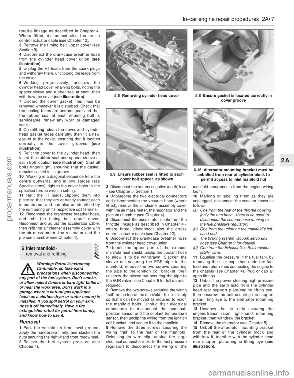
4Disconnect the crankcase breather hose
from the cylinder head cover union (see
illustration).
5Unplug the HT leads from the spark plugs
and withdraw them, unclipping the leads from
the cover.
6Working progressively, unscrew the
cylinder head cover retaining bolts, noting the
spacer sleeve and rubber seal at each, then
withdraw the cover (see illustration).
7Discard the cover gasket; this mustbe
renewed whenever it is disturbed. Check that
the sealing faces are undamaged, and that
the rubber seal at each retaining bolt is
serviceable; renew any worn or damaged
seals.
8On refitting, clean the cover and cylinder
head gasket faces carefully, then fit a new
gasket to the cover, ensuring that it locates
correctly in the cover grooves (see
illustration).
9Refit the cover to the cylinder head, then
insert the rubber seal and spacer sleeve at
each bolt location (see illustration). Start all
bolts finger-tight, ensuring that the gasket
remains seated in its groove.
10Working in a diagonal sequence from the
centre outwards, and in two stages (see
Specifications), tighten the cover bolts to the
specified torque wrench setting.
11Refit the HT leads, clipping them into
place so that they are correctly routed; each
is numbered, and can also be identified by
the numbering on its respective coil terminal.
12Reconnect the crankcase breather hose,
and refit the timing belt upper cover.
Reconnect and adjust the accelerator cable,
then refit the air cleaner assembly cover with
the air mass meter, the resonator and the
plenum chamber (see Chapter 4).
Warning: Petrol is extremely
flammable, so take extra
precautions when disconnecting
any part of the fuel system. Don’t smoke,
or allow naked flames or bare light bulbs in
or near the work area. Don’t work in a
garage where a natural gas appliance
(such as a clothes dryer or water heater) is
installed. If you spill petrol on your skin,
rinse it off immediately. Have a fire
extinguisher rated for petrol fires handy,
and know how to use it.
Removal
1Park the vehicle on firm, level ground,
apply the handbrake firmly, and slacken the
nuts securing the right-hand front roadwheel.
2Relieve the fuel system pressure (see
Chapter 4).3Disconnect the battery negative (earth) lead
- see Chapter 5, Section 1.
4Unplugging the two electrical connectors
and disconnecting the vacuum hose (where
fitted), remove the air cleaner assembly cover
with the air mass meter, the resonator and the
plenum chamber (see Chapter 4).
5Disconnect the accelerator cable from the
throttle linkage as described in Chapter 4 -
where fitted, disconnect also the cruise
control actuator cable (see Chapter 12).
6Disconnect the crankcase breather hose
from the cylinder head cover union.
7Unbolt the upper part of the exhaust
manifold heat shield; unclip the coolant hose
to allow it to be withdrawn. Slacken the
sleeve nut securing the EGR pipe to the
manifold, remove the two screws securing
the pipe to the ignition coil bracket, then
unscrew the sleeve nut securing the pipe to
the EGR valve - see Chapter 6 for full details if
required.
8Remove the two screws securing the wiring
“rail” to the top of the manifold - this is simply
so that it can be moved as required to reach
the manifold bolts. Unplug their electrical
connectors to disconnect the camshaft
position sensor and the coolant temperature
sensor, then unclip the wiring from the ignition
coil bracket, and secure it to the manifold.
9Remove the three screws securing the
wiring “rail” to the rear of the manifold.
Releasing its wire clip, unplug the large
electrical connector (next to the fuel pressure
regulator) to disconnect the wiring of themanifold components from the engine wiring
loom.
10Marking or labelling them as they are
unplugged, disconnect the vacuum hoses as
follows:
(a) One from the rear of the throttle housing
(only the one hose - there is no need to
disconnect the second hose running to
the fuel pressure regulator).
(b) One from the union on the manifold’s left-
hand end.
(c) The braking system vacuum servo unit
hose (see Chapter 9 for details).
(d) One from the Exhaust Gas Recirculation
(EGR) valve.
11Equalise the pressure in the fuel tank by
removing the filler cap, then undo the fuel
feed and return lines connecting the engine to
the chassis (see Chapter 4). Plug or cap all
open fittings.
12Unbolt the power steering high-pressure
pipe and the earth lead from the cylinder
head rear support plate/engine lifting eye,
then unscrew the bolt securing the support
plate/lifting eye to the alternator mounting
bracket.
13Unscrew the six nuts securing the
engine/transmission right-hand mounting
bracket, then withdraw the bracket.
14Remove the alternator (see Chapter 5).
15Unbolt the alternator mounting bracket
from the rear of the cylinder block and
withdraw it, together with the cylinder head
rear support plate/engine lifting eye (see
illustration).
6 Inlet manifold -
removal and refitting
In-car engine repair procedures 2A•7
2A
5.8 Ensure gasket is located correctly in
cover groove5.6 Removing cylinder head cover
5.9 Ensure rubber seal is fitted to each
cover bolt spacer, as shown6.15 Alternator mounting bracket must be
unbolted from rear of cylinder block to
permit access to inlet manifold nut
procarmanuals.com
Page 48 of 279
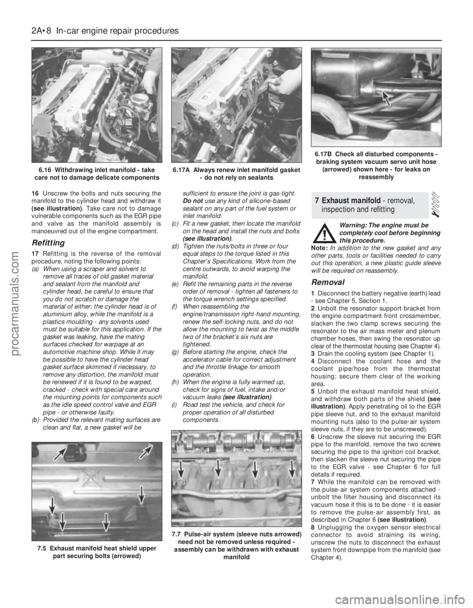
16Unscrew the bolts and nuts securing the
manifold to the cylinder head and withdraw it
(see illustration). Take care not to damage
vulnerable components such as the EGR pipe
and valve as the manifold assembly is
manoeuvred out of the engine compartment.
Refitting
17Refitting is the reverse of the removal
procedure, noting the following points:
(a) When using a scraper and solvent to
remove all traces of old gasket material
and sealant from the manifold and
cylinder head, be careful to ensure that
you do not scratch or damage the
material of either; the cylinder head is of
aluminium alloy, while the manifold is a
plastics moulding - any solvents used
must be suitable for this application. If the
gasket was leaking, have the mating
surfaces checked for warpage at an
automotive machine shop. While it may
be possible to have the cylinder head
gasket surface skimmed if necessary, to
remove any distortion, the manifold must
be renewed if it is found to be warped,
cracked - check with special care around
the mounting points for components such
as the idle speed control valve and EGR
pipe - or otherwise faulty.
(b) Provided the relevant mating surfaces are
clean and flat, a new gasket will besufficient to ensure the joint is gas-tight.
Do notuse any kind of silicone-based
sealant on any part of the fuel system or
inlet manifold.
(c) Fit a new gasket, then locate the manifold
on the head and install the nuts and bolts
(see illustration).
(d) Tighten the nuts/bolts in three or four
equal steps to the torque listed in this
Chapter’s Specifications. Work from the
centre outwards, to avoid warping the
manifold.
(e) Refit the remaining parts in the reverse
order of removal - tighten all fasteners to
the torque wrench settings specified.
(f) When reassembling the
engine/transmission right-hand mounting,
renew the self-locking nuts, and do not
allow the mounting to twist as the middle
two of the bracket’s six nuts are
tightened.
(g) Before starting the engine, check the
accelerator cable for correct adjustment
and the throttle linkage for smooth
operation.
(h) When the engine is fully warmed up,
check for signs of fuel, intake and/or
vacuum leaks (see illustration).
(i) Road test the vehicle, and check for
proper operation of all disturbed
components.Warning: The engine must be
completely cool before beginning
this procedure.
Note:In addition to the new gasket and any
other parts, tools or facilities needed to carry
out this operation, a new plastic guide sleeve
will be required on reassembly.
Removal
1Disconnect the battery negative (earth) lead
- see Chapter 5, Section 1.
2Unbolt the resonator support bracket from
the engine compartment front crossmember,
slacken the two clamp screws securing the
resonator to the air mass meter and plenum
chamber hoses, then swing the resonator up
clear of the thermostat housing (see Chapter 4).
3Drain the cooling system (see Chapter 1).
4Disconnect the coolant hose and the
coolant pipe/hose from the thermostat
housing; secure them clear of the working
area.
5Unbolt the exhaust manifold heat shield,
and withdraw both parts of the shield (see
illustration). Apply penetrating oil to the EGR
pipe sleeve nut, and to the exhaust manifold
mounting nuts (also to the pulse-air system
sleeve nuts, if they are to be unscrewed).
6Unscrew the sleeve nut securing the EGR
pipe to the manifold, remove the two screws
securing the pipe to the ignition coil bracket,
then slacken the sleeve nut securing the pipe
to the EGR valve - see Chapter 6 for full
details if required.
7While the manifold can be removed with
the pulse-air system components attached -
unbolt the filter housing and disconnect its
vacuum hose if this is to be done - it is easier
to remove the pulse-air assembly first, as
described in Chapter 6 (see illustration).
8Unplugging the oxygen sensor electrical
connector to avoid straining its wiring,
unscrew the nuts to disconnect the exhaust
system front downpipe from the manifold (see
Chapter 4).
7 Exhaust manifold - removal,
inspection and refitting
2A•8 In-car engine repair procedures
6.16 Withdrawing inlet manifold - take
care not to damage delicate components6.17A Always renew inlet manifold gasket
- do not rely on sealants
6.17B Check all disturbed components -
braking system vacuum servo unit hose
(arrowed) shown here - for leaks on
reassembly
7.5 Exhaust manifold heat shield upper
part securing bolts (arrowed)
7.7 Pulse-air system (sleeve nuts arrowed)
need not be removed unless required -
assembly can be withdrawn with exhaust
manifold
procarmanuals.com
Page 62 of 279
the gasket, move the pump into the correct
position, and tighten its bolts to the specified
torque wrench setting.
14Check that the pump is correctly located;
if necessary, unbolt it again, and repeat the
full procedure to ensure that the pump is
correctly aligned.
15Fit a new crankshaft right-hand oil seal
(see Section 20).
16Using grease to stick the gasket in place
on the pump, refit the pick-up/strainer pipe,
tightening its screws and nut to their specified
torque wrench settings (see illustration).
17The remainder of reassembly is the
reverse of the removal procedure, referring to
the relevant text for details where required.
1Drain the cooling system (see Chapter 1).
Disconnect the coolant hoses from the oil
cooler.
2Unscrew the oil filter (see Chapter 1) -
catch any escaping oil in a drip tray.
3Unscrew the filter adaptor from the oil
pump, and withdraw the oil cooler; note how
its unions are aligned, and be prepared for oil
loss from the cooler.
4Refitting is the reverse of the removal
procedure, noting the following points:(a) Renew all O-rings and seals disturbed on
removal.
(b) Align the cooler’s unions as noted on
removal, and tighten the adaptor to the
specified torque wrench setting.
(c) Refill the cooling system (see Chapter 1).
(d) Refit the oil filter, then check the engine
oil level, and top-up as necessary (see
Chapter 1).
(e) Check for signs of oil or coolant leaks once
the engine has been restarted and warmed-
up to normal operating temperature.
1With the vehicle parked on firm level
ground, open the bonnet and disconnect the
battery negative (earth) lead - see Chapter 5,
Section 1.
2Raise the front of the vehicle, and support it
securely on axle stands.
3Undo the two screws, and remove the
sensor’s cover from the front of the sump
(see illustration).
4Unplug the wiring from the sensor (see
illustration). Where necessary, unplug the
electrical connector to disconnect the sensor
wiring, and unclip the connector to release
the wiring from the vehicle.
5Unscrew the sensor, and quickly plug the
sump aperture to minimise oil loss; note the
sensor’s seal.6Refitting is the reverse of the removal
procedure; renew the sensor’s seal if it is
worn or damaged, and tighten the sensor to
the specified torque wrench setting. Check
the engine oil level, and top-up as necessary
(see Chapter 1) - check for signs of oil leaks
once the engine has been restarted and
warmed-up to normal operating temperature.
1The switch is screwed into the rear of the
cylinder block, above the right-hand
driveshaft’s support bearing (see
illustration).
2With the vehicle parked on firm level
ground, open the bonnet and disconnect the
battery negative (earth) lead - see Chapter 5,
Section 1.
3Raise the front of the vehicle, and support it
securely on axle stands.
4Unplug the wiring from the switch, and
unscrew it; be prepared for some oil loss.
5Refitting is the reverse of the removal
procedure; apply a thin smear of suitable
sealant to the switch threads, and tighten it to
the specified torque wrench setting. Check
the engine oil level, and top-up as necessary
(see Chapter 1). Check for signs of oil leaks
once the engine has been restarted and
warmed-up to normal operating temperature.
Note:Don’t try to prise these seals out
without removing the oil pump or seal carrier -
the seals are too soft, and the amount of
space available is too small, for this to be
possible without considerable risk of damage
to the seal housing and/or the crankshaft
journal. Follow exactly the procedure given
below.
Right-hand seal
1Remove the oil pump (see Section 16).
2Drive the oil seal out of the pump from
behind (see illustration).
20 Crankshaft oil seals -
renewal
19 Oil pressure warning light
switch - removal and refitting
18 Oil level sensor-
removal and refitting
17 Oil cooler -
removal and refitting
2A•22 In-car engine repair procedures
16.16 Use new gasket when refitting oil
pick-up pipe to pump18.3 Remove screws (arrowed) to remove
oil level sensor cover . . .18.4 . . . disconnecting wiring from sensor
19.1 Oil pressure warning light switch
(arrowed) is screwed into rear of cylinder
block, above right-hand driveshaft support
bearing
20.2 Driving out crankshaft right-hand oil
seal
procarmanuals.com
Page 64 of 279
Removal
1Remove the transmission (see the relevant
Part of Chapter 7). Now is a good time to
check components such as oil seals and
renew them if necessary.
2Where appropriate, remove the clutch
(Chapter 8). Now is a good time to check or
renew the clutch components and pilot
bearing.
3Use a centre-punch or paint to make
alignment marks on the flywheel/driveplate
and crankshaft, to ensure correct alignment
during refitting.
4Prevent the flywheel/driveplate from
turning by locking the ring gear teeth, or by
bolting a strap between the flywheel/
driveplate and the cylinder block/
crankcase. Slacken the bolts evenly until all
are free.
5Remove each bolt in turn, and ensure that
new replacements are obtained for
reassembly; these bolts are subjected to
severe stresses, and so must be renewed,
regardless of their apparent condition,
whenever they are disturbed.
6Noting the reinforcing plate (automatic
transmission-equipped models only),
withdraw the flywheel/driveplate; do not drop
it - it is very heavy.
Inspection
7Clean the flywheel/driveplate to remove
grease and oil. Inspect the surface for cracks,
rivet grooves, burned areas and score marks.
Light scoring can be removed with emery
cloth. Check for cracked and broken ring gear
teeth. Lay the flywheel/driveplate on a flat
surface, and use a straight edge to check for
warpage.
8Clean and inspect the mating surfaces of
the flywheel/driveplate and the crankshaft. If
the crankshaft left-hand seal is leaking, renew
it (see Section 20) before refitting the
flywheel/driveplate.
9While the flywheel/driveplate is removed,clean carefully its inboard (right-hand) face,
particularly the recesses which serve as the
reference points for the crankshaft
speed/position sensor. Clean the sensor’s tip,
and check that the sensor is securely
fastened.
Refitting
10On refitting, ensure that the
engine/transmission adaptor plate is in place
(where necessary), then fit the
flywheel/driveplate to the crankshaft so that
all bolt holes align - it will fit only one way -
check this using the marks made on removal.
Do not forget the reinforcing plate (where
fitted).
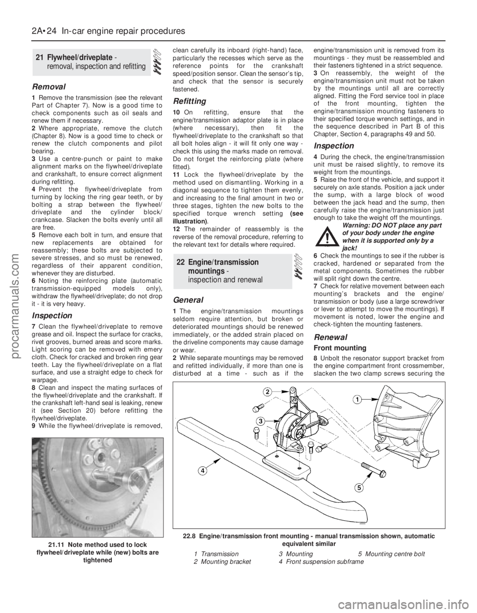
11Lock the flywheel/driveplate by the
method used on dismantling. Working in a
diagonal sequence to tighten them evenly,
and increasing to the final amount in two or
three stages, tighten the new bolts to the
specified torque wrench setting (see
illustration).
12The remainder of reassembly is the
reverse of the removal procedure, referring to
the relevant text for details where required.
General
1The engine/transmission mountings
seldom require attention, but broken or
deteriorated mountings should be renewed
immediately, or the added strain placed on
the driveline components may cause damage
or wear.
2While separate mountings may be removed
and refitted individually, if more than one is
disturbed at a time - such as if theengine/transmission unit is removed from its
mountings - they must be reassembled and
their fasteners tightened in a strict sequence.
3On reassembly, the weight of the
engine/transmission unit must not be taken
by the mountings until all are correctly
aligned. Fitting the Ford service tool in place
of the front mounting, tighten the
engine/transmission mounting fasteners to
their specified torque wrench settings, and in
the sequence described in Part B of this
Chapter, Section 4, paragraphs 49 and 50.
Inspection
4During the check, the engine/transmission
unit must be raised slightly, to remove its
weight from the mountings.
5Raise the front of the vehicle, and support it
securely on axle stands. Position a jack under
the sump, with a large block of wood
between the jack head and the sump, then
carefully raise the engine/transmission just
enough to take the weight off the mountings.
Warning: DO NOT place any part
of your body under the engine
when it is supported only by a
jack!
6Check the mountings to see if the rubber is
cracked, hardened or separated from the
metal components. Sometimes the rubber
will split right down the centre.
7Check for relative movement between each
mounting’s brackets and the engine/
transmission or body (use a large screwdriver
or lever to attempt to move the mountings). If
movement is noted, lower the engine and
check-tighten the mounting fasteners.
Renewal
Front mounting
8Unbolt the resonator support bracket from
the engine compartment front crossmember,
slacken the two clamp screws securing the
22 Engine/transmission
mountings -
inspection and renewal
21 Flywheel/driveplate -
removal, inspection and refitting
2A•24 In-car engine repair procedures
21.11 Note method used to lock
flywheel/driveplate while (new) bolts are
tightened
22.8 Engine/transmission front mounting - manual transmission shown, automatic
equivalent similar
1 Transmission 3 Mounting 5 Mounting centre bolt
2 Mounting bracket 4 Front suspension subframe
procarmanuals.com
Page 70 of 279
safely and with relative ease, and which may
have to be hired or borrowed, includes (in
addition to the engine hoist) a heavy-duty trolley
jack, a strong pair of axle stands, some wooden
blocks, and an engine dolly (a low, wheeled
platform capable of taking the weight of the
engine/transmission, so that it can be moved
easily when on the ground). A complete set of
spanners and sockets (as described in the front
of this manual) will obviously be needed,
together with plenty of rags and cleaning
solvent for mopping-up spilled oil, coolant and
fuel. If the hoist is to be hired, make sure that
you arrange for it in advance, and perform all of
the operations possible without it beforehand.
This will save you money and time.
Plan for the vehicle to be out of use for
quite a while. A machine shop will be required
to perform some of the work which the do-it-
yourselfer can’t accomplish without special
equipment. These establishments often have
a busy schedule, so it would be a good idea
to consult them before removing the engine,
to accurately estimate the amount of time
required to rebuild or repair components that
may need work.
Always be extremely careful when removing
and installing the engine/transmission.
Serious injury can result from careless
actions. By planning ahead and taking your
time, the job (although a major task) can be
accomplished successfully.
Warning: Petrol is extremely
flammable, so take extra
precautions when disconnecting
any part of the fuel system. Don’t
smoke, or allow naked flames or bare light
bulbs in or near the work area, and don’t
work in a garage where a natural gas
appliance (such as a clothes dryer or water
heater) is installed. If you spill petrol on
your skin, rinse it off immediately. Have a
fire extinguisher rated for petrol fires
handy, and know how to use it.Note: Read through the entire Section, as well
as reading the advice in the preceding Section,
before beginning this procedure. The engine
and transmission are removed as a unit,
lowered to the ground and removed from
underneath, then separated outside the vehicle.
Removal
1Park the vehicle on firm, level ground, apply
the handbrake firmly, and slacken the nuts
securing both front roadwheels.
2Relieve the fuel system pressure (see
Chapter 4).
3Disconnect the battery negative (earth) lead
- see Chapter 5, Section 1. For better access
the battery may be removed completely (see
Chapter 5).
4Place protective covers on the wings and
engine compartment front crossmember, then
remove the bonnet (see Chapter 11).
5Whenever you disconnect any vacuum
lines, coolant and emissions hoses, wiring
loom connectors, earth straps and fuel lines
as part of the following procedure, always
label them clearly, so that they can be
correctly reassembled.
6Unplug the two electrical connectors,disconnect the vacuum hose (where fitted)
and disconnect the crankcase breather hose
from the cylinder head cover, then remove the
complete air cleaner assembly, with the air
mass meter, the resonator and the plenum
chamber (see Chapter 4).
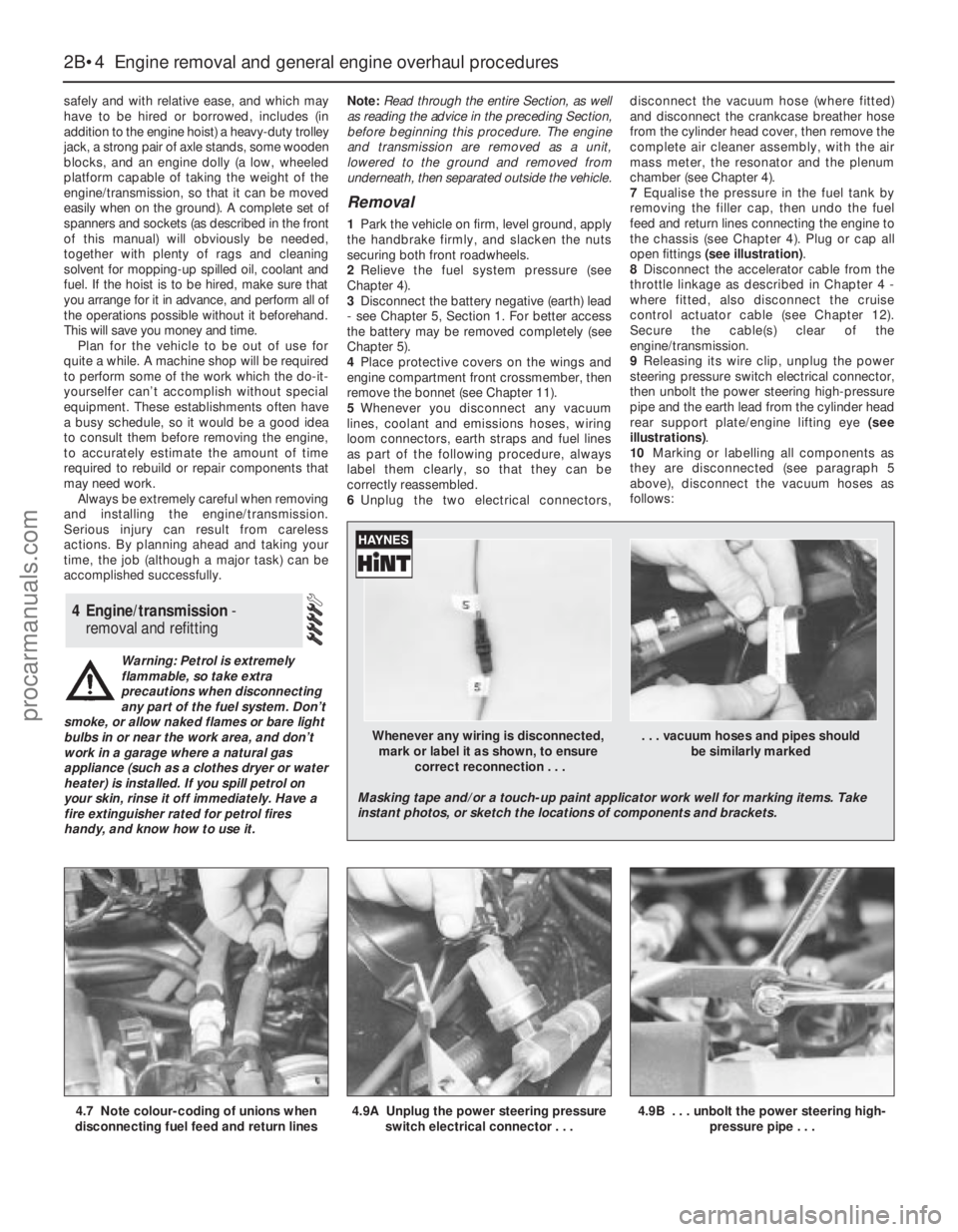
7Equalise the pressure in the fuel tank by
removing the filler cap, then undo the fuel
feed and return lines connecting the engine to
the chassis (see Chapter 4). Plug or cap all
open fittings (see illustration).
8Disconnect the accelerator cable from the
throttle linkage as described in Chapter 4 -
where fitted, also disconnect the cruise
control actuator cable (see Chapter 12).
Secure the cable(s) clear of the
engine/transmission.
9Releasing its wire clip, unplug the power
steering pressure switch electrical connector,
then unbolt the power steering high-pressure
pipe and the earth lead from the cylinder head
rear support plate/engine lifting eye (see
illustrations).
10Marking or labelling all components as
they are disconnected (see paragraph 5
above), disconnect the vacuum hoses as
follows:
4 Engine/transmission -
removal and refitting
2B•4 Engine removal and general engine overhaul procedures
4.7 Note colour-coding of unions when
disconnecting fuel feed and return lines4.9A Unplug the power steering pressure
switch electrical connector . . .4.9B . . . unbolt the power steering high-
pressure pipe . . .
Whenever any wiring is disconnected, . . . vacuum hoses and pipes should
mark or label it as shown, to ensure be similarly marked
correct reconnection . . .
Masking tape and/or a touch-up paint applicator work well for marking items. Take
instant photos, or sketch the locations of components and brackets.
procarmanuals.com
Page 72 of 279
inner wing panel, release the engine
wiring loom and refit the power steering
fluid reservoir.
(g) Secure the engine wiring loom neatly to
the engine/transmission so that it cannot
be damaged as the unit is removed from
the vehicle.
14Unbolt both parts of the exhaust manifold
heat shield; unclip the coolant hose to allow
the upper part to be withdrawn.
15Remove the auxiliary drivebelt (see
Chapter 1).
16Unbolt the power steering pump (see
Chapter 10); secure it as far as possible
(without disconnecting the system’s hoses)
clear of the engine/transmission.
17Raise the vehicle and support it securely
on axle stands, then remove the front
roadwheels. Drain the cooling system and (if
the engine is to be dismantled) drain the
engine oil and remove the oil filter (see
Chapter 1). Also drain the transmission as
described in the relevant Part of Chapter 7.
18Withdraw the lower part of the exhaust
manifold heat shield.
19Unscrew the nuts to disconnect the
exhaust system front downpipe from the
manifold, then unhook all the system’s rubber
mountings and withdraw the complete
exhaust system from under the vehicle (see
Chapter 4 for details).
20Where the vehicle is fitted with manual
transmission, mark their positions, then
disconnect the gearchange linkage and
transmission support rods from the rear of the
transmission. Unscrew the retaining nuts, and
withdraw the gear linkage heat shield from the
underbody. Unbolt the rear end of the linkage
from the underbody, swivel the linkage around
to the rear, and tie it to the underbody (see
Chapter 7, Part A, for details).
21Disconnect both anti-roll bar links from
their respective suspension strut - note the
flexible brake hose bracket attached to each
link stud - and both track rod ends from their
steering knuckles. Unfasten the clamp bolt
securing each front suspension lower arm
balljoint to its steering knuckle (see Chap-
ter 10 for details). Check that both balljoints
can be released from the knuckle assemblies
when required, but leave them in place for thetime being, secured by the clamp bolts if
necessary.
22Where the vehicle is fitted with air
conditioning, unbolt the accumulator/
dehydrator from the subframe; secure it as far
as possible (without disconnecting the
system’s hoses) clear of the engine/
transmission.
Warning: Do not disconnect the
refrigerant hoses.
23Unbolt the steering gear from the
subframe; if the bolts are not accessible from
above, a Ford service tool will be required to
reach them from underneath the vehicle (see
Chapter 10 for details).
24Unscrew the two bolts securing the power
steering system pipes to the right-hand side
of the subframe.
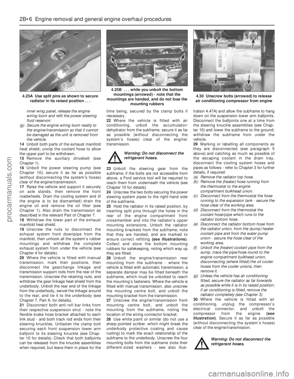
25Hold the radiator in its raised position, by
inserting split pins through the holes in the
rear of the engine compartment front
crossmember and into the radiator’s upper
mounting extensions. Unbolt the radiator
mounting brackets from the subframe; note
that they are handed, and are marked to
ensure correct refitting (see illustrations).
Collect and store the bottom mounting
rubbers for safekeeping, noting which way up
they are fitted.
26Unbolt the engine/transmission rear
mounting from the subframe - where the
vehicle is fitted with automatic transmission, a
separate damper may be fitted beneath the
subframe, which must be unbolted to reach
the mounting’s fasteners. Where the vehicle is
fitted with manual transmission, also unscrew
the mounting centre bolt, and unbolt the
mounting bracket from the transmission.
27Unscrew the engine/transmission front
mounting centre bolt, and unbolt the
mounting from the subframe, noting the
location of the wiring connector bracket.
28Use white paint or similar (do not use a
sharp-pointed scriber, which might break the
underbody protective coating and cause
rusting) to mark the exact relationship of the
subframe to the underbody. Unscrew the four
mounting bolts from the subframe (note their
different-sized washers - see also illus-tration 4.47A) and allow the subframe to hang
down on the suspension lower arm balljoints.
Disconnect the balljoints one at a time from
the steering knuckle assemblies (see Chap-
ter 10) and lower the subframe to the ground;
withdraw the subframe from under the
vehicle.
29Marking or labelling all components as
they are disconnected (see paragraph 5
above) and catching as much as possible of
the escaping coolant in the drain tray,
disconnect the cooling system hoses and
pipes as follows - refer to Chapter 3 for further
details, if required:
(a) Remove the radiator top hose.
(b) Remove the (heater) hose running from
the thermostat to the engine
compartment bulkhead union.
(c) Disconnect from the thermostat the hose
running to the expansion tank - secure the
hose clear of the working area.
(d) Disconnect from the thermostat the
coolant hose/pipe which runs to the
radiator bottom hose.
(e) Disconnect the radiator bottom hose from
the radiator union, from the (sump) heater
coolant pipe and from the water pump
union - secure the hose clear of the
working area.
(f) Unbolt the (heater) coolant pipe from the
sump, trace the pipe/hose round to the
engine compartment bulkhead union,
disconnecting (where fitted) the oil cooler
hoses from the cooler unions, then
remove it.
(g) Unless the vehicle has air conditioning
fitted, secure the radiator as far forwards
as possible while it is in its raised position;
if air conditioning is fitted, remove the
radiator completely (see Chapter 3).
30Where the vehicle is fitted with air
conditioning, unplug the compressor’s
electrical connector, and unbolt the
compressor from the engine (see
illustration). Secure it as far as possible
(without disconnecting the system’s hoses)
clear of the engine/transmission.
Warning: Do not disconnect the
refrigerant hoses.
2B•6 Engine removal and general engine overhaul procedures
4.25A Use split pins as shown to secure
radiator in its raised position . . .
4.25B . . . while you unbolt the bottom
mountings (arrowed) - note that the
mountings are handed, and do not lose the
mounting rubbers
4.30 Unscrew bolts (arrowed) to release
air conditioning compressor from engine
procarmanuals.com