1993 FORD MONDEO brake fluid
[x] Cancel search: brake fluidPage 20 of 279
This Chapter is designed to help the home
mechanic maintain the Ford Mondeo models
for peak performance, economy, safety and
long life.
On the following pages are Sections
dealing specifically with each item on the
maintenance schedule. Visual checks,
adjustments, component replacement and
other helpful items are included. Refer to the
accompanying illustrations of the engine
compartment and the underside of the vehicle
for the location of various components.
Servicing your Mondeo in accordance with
the mileage/time maintenance schedule and
the following Sections will provide it with a
planned maintenance programme, which
should result in a long and reliable service life.
This is a comprehensive plan, so maintaining
some items but not others at the specified
service intervals will not produce the same
results.
As you service your Mondeo, you will
discover that many of the procedures can -
and should - be grouped together, because of
the nature of the particular procedure you’re
performing, or because of the close proximity
to one another of two otherwise-unrelated
components.
For example, if the vehicle is raised for anyreason, you should inspect the exhaust,
suspension, steering and fuel systems while
you’re under the vehicle. When you’re
checking the tyres, it makes good sense to
check the brakes and wheel bearings,
especially if the roadwheels have already
been removed.
Finally, let’s suppose you have to borrow or
hire a torque wrench. Even if you only need to
tighten the spark plugs, you might as well
check the torque of as many critical fasteners
as time allows.
The first step of this maintenance
programme is to prepare yourself before the
actual work begins. Read through all the
Sections which are relevant to the procedures
you’re planning to carry out, then make a list
of, and gather together, all the parts and tools
you will need to do the job. If it looks as if you
might run into problems during a particular
segment of some procedure, seek advice
from your local parts man or dealer service
department.
Ford state that, where antifreeze to
specification ESD-M97B-49-A (the type with
which the vehicle’s cooling system would
have been filled on production at the factory)
is used, it will last the lifetime of the vehicle.This is subject to it being used in the
recommended concentration, unmixed with
any other type of antifreeze or additive, and
topped-up when necessary using only that
antifreeze mixed 50/50 with clean water. If any
other type of antifreeze is added, the lifetime
guarantee no longer applies; to restore the
lifetime protection, the system must be
drained and thoroughly reverse-flushed
before fresh coolant mixture is poured in.
If the vehicle’s history (and therefore the
quality of the antifreeze in it) is unknown,
owners who wish to follow Ford’s
recommendations are advised to drain and
thoroughly reverse-flush the system, as
outlined in Section 28, before refilling with
fresh coolant mixture. If the appropriate
quality of antifreeze is used, the coolant can
then be left for the life of the vehicle.
If any antifreeze other than Ford’s is to be
used, the coolant must be renewed at regular
intervals to provide an equivalent degree of
protection; the conventional recommendation
is to renew the coolant every two years.
The above assumes the use of a mixture (in
exactly the specified concentration) of clean,
soft water and of antifreeze to Ford’s
specification or equivalent. It is also assumed
that the cooling system is maintained in a
scrupulously-clean condition, by ensuring that
only clean coolant is added on topping-up,
and by thorough reverse-flushing whenever
the coolant is drained (Section 28).
2 Coolant renewal
1 Introduction
1•6Weekly checks
Weekly checks
General
1Fluids are an essential part of the
lubrication, cooling, braking and other
systems. Because these fluids gradually
become depleted and/or contaminated during
normal operation of the vehicle, they must be
periodically replenished. See “Lubricants and
fluids and capacities”at the beginning of this
Chapter before adding fluid to any of the
following components. Note:The vehicle
must be on level ground before fluid levels can
be checked.
Engine oil
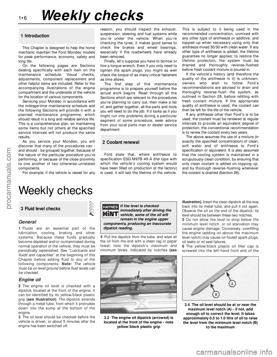
2The engine oil level is checked with a
dipstick located at the front of the engine; it
can be identified by its yellow/black plastic
grip (see illustration). The dipstick extends
through a metal tube, from which it protrudes
down into the sump at the bottom of the
engine.
3The oil level should be checked before the
vehicle is driven, or about 5 minutes after the
engine has been switched off.4Pull the dipstick from the tube, and wipe all
the oil from the end with a clean rag or paper
towel; note the dipstick’s maximum and
minimum levels, indicated by notches (seeillustration). Insert the clean dipstick all the way
back into its metal tube, and pull it out again.
Observe the oil on the end of the dipstick; its
level should be between these two notches.
5Do not allow the level to drop below the
minimum level notch, or oil starvation may
cause engine damage. Conversely, overfilling
the engine (adding oil above the maximum
level notch) may cause oil-fouled spark plugs,
oil leaks or oil seal failures.
6The yellow/black plastic oil filler cap is
screwed into the left-hand front end of the
3 Fluid level checks
3.2 The engine oil dipstick (arrowed) is
located at the front of the engine - note
yellow/black plastic grip
3.4 The oil level should be at or near the
maximum level notch (A) - if not, add
enough oil to correct the level. It takes
approximately 0.5 to 1.0 litre of oil to raise
the level from the minimum level notch (B)
to the maximum
If the level is checked
immediately after driving the
vehicle, some of the oil will
remain in the engine upper
components, producing an inaccurate
dipstick reading.
procarmanuals.com
Page 22 of 279
15Coolant hydrometers are available at
most automotive accessory shops. If the
specific gravity of a sample taken from the
expansion tank (when the engine is switched
off and fully cooled down) is less than that
specified, the coolant mixture strength has
fallen below the minimum. If this is found,
either the coolant strength must be restored
by adding neat antifreeze to Ford’s
specification (if that is what is in the system)
or by draining and flushing the system, then
refilling it with fresh coolant mixture of the
correct ratio (if any other type of antifreeze is
being used).
16When checking the coolant level, always
note its condition; it should be relatively clear.
If it is brown or rust-coloured, the system
should be drained, flushed and refilled. If
antifreeze has been used which does not
meet Ford’s specification, its corrosion
inhibitors will lose their effectiveness with
time; such coolant must be renewed regularly,
even if it appears to be in good condition,
usually at the intervals suggested at the
beginning of Section 2 of this Chapter.
Windscreen/tailgate and
headlight washer fluid
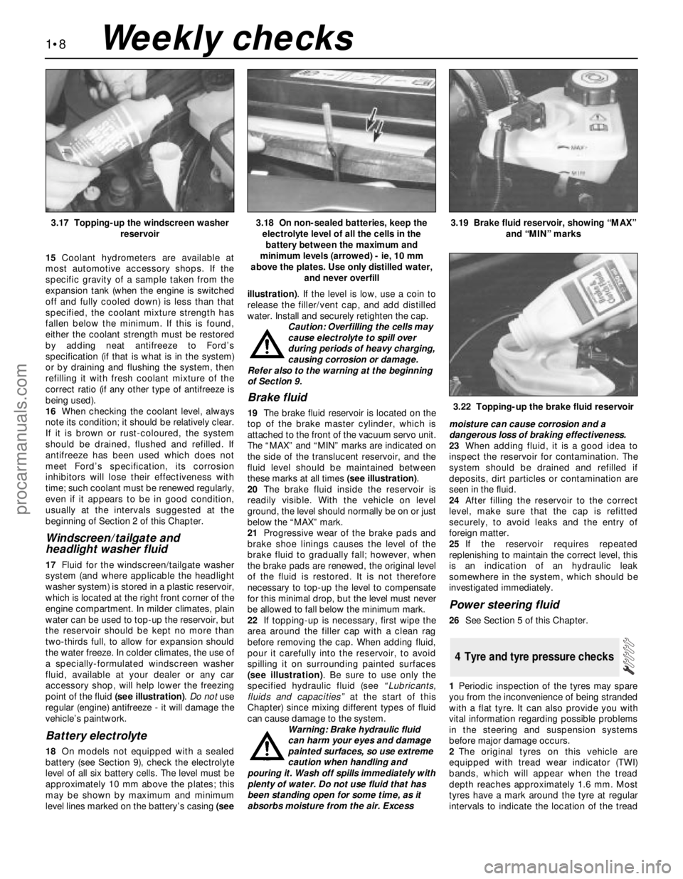
17Fluid for the windscreen/tailgate washer
system (and where applicable the headlight
washer system) is stored in a plastic reservoir,
which is located at the right front corner of the
engine compartment. In milder climates, plain
water can be used to top-up the reservoir, but
the reservoir should be kept no more than
two-thirds full, to allow for expansion should
the water freeze. In colder climates, the use of
a specially-formulated windscreen washer
fluid, available at your dealer or any car
accessory shop, will help lower the freezing
point of the fluid (see illustration). Do notuse
regular (engine) antifreeze - it will damage the
vehicle’s paintwork.
Battery electrolyte
18On models not equipped with a sealed
battery (see Section 9), check the electrolyte
level of all six battery cells. The level must be
approximately 10 mm above the plates; this
may be shown by maximum and minimum
level lines marked on the battery’s casing (seeillustration). If the level is low, use a coin to
release the filler/vent cap, and add distilled
water. Install and securely retighten the cap.
Caution: Overfilling the cells may
cause electrolyte to spill over
during periods of heavy charging,
causing corrosion or damage.
Refer also to the warning at the beginning
of Section 9.
Brake fluid
19The brake fluid reservoir is located on the
top of the brake master cylinder, which is
attached to the front of the vacuum servo unit.
The “MAX” and “MIN” marks are indicated on
the side of the translucent reservoir, and the
fluid level should be maintained between
these marks at all times (see illustration).
20The brake fluid inside the reservoir is
readily visible. With the vehicle on level
ground, the level should normally be on or just
below the “MAX” mark.
21Progressive wear of the brake pads and
brake shoe linings causes the level of the
brake fluid to gradually fall; however, when
the brake pads are renewed, the original level
of the fluid is restored. It is not therefore
necessary to top-up the level to compensate
for this minimal drop, but the level must never
be allowed to fall below the minimum mark.
22If topping-up is necessary, first wipe the
area around the filler cap with a clean rag
before removing the cap. When adding fluid,
pour it carefully into the reservoir, to avoid
spilling it on surrounding painted surfaces
(see illustration). Be sure to use only the
specified hydraulic fluid (see “Lubricants,
fluids and capacities”at the start of this
Chapter) since mixing different types of fluid
can cause damage to the system.
Warning: Brake hydraulic fluid
can harm your eyes and damage
painted surfaces, so use extreme
caution when handling and
pouring it. Wash off spills immediately with
plenty of water. Do not use fluid that has
been standing open for some time, as it
absorbs moisture from the air. Excessmoisture can cause corrosion and a
dangerous loss of braking effectiveness.
23When adding fluid, it is a good idea to
inspect the reservoir for contamination. The
system should be drained and refilled if
deposits, dirt particles or contamination are
seen in the fluid.
24After filling the reservoir to the correct
level, make sure that the cap is refitted
securely, to avoid leaks and the entry of
foreign matter.
25If the reservoir requires repeated
replenishing to maintain the correct level, this
is an indication of an hydraulic leak
somewhere in the system, which should be
investigated immediately.
Power steering fluid
26See Section 5 of this Chapter.
1Periodic inspection of the tyres may spare
you from the inconvenience of being stranded
with a flat tyre. It can also provide you with
vital information regarding possible problems
in the steering and suspension systems
before major damage occurs.
2The original tyres on this vehicle are
equipped with tread wear indicator (TWI)
bands, which will appear when the tread
depth reaches approximately 1.6 mm. Most
tyres have a mark around the tyre at regular
intervals to indicate the location of the tread
4 Tyre and tyre pressure checks
1•8
3.17 Topping-up the windscreen washer
reservoir3.18 On non-sealed batteries, keep the
electrolyte level of all the cells in the
battery between the maximum and
minimum levels (arrowed) - ie, 10 mm
above the plates. Use only distilled water,
and never overfill3.19 Brake fluid reservoir, showing “MAX”
and “MIN” marks
3.22 Topping-up the brake fluid reservoir
Weekly checks
procarmanuals.com
Page 25 of 279
Every 10 000 miles or 12 months
1•11
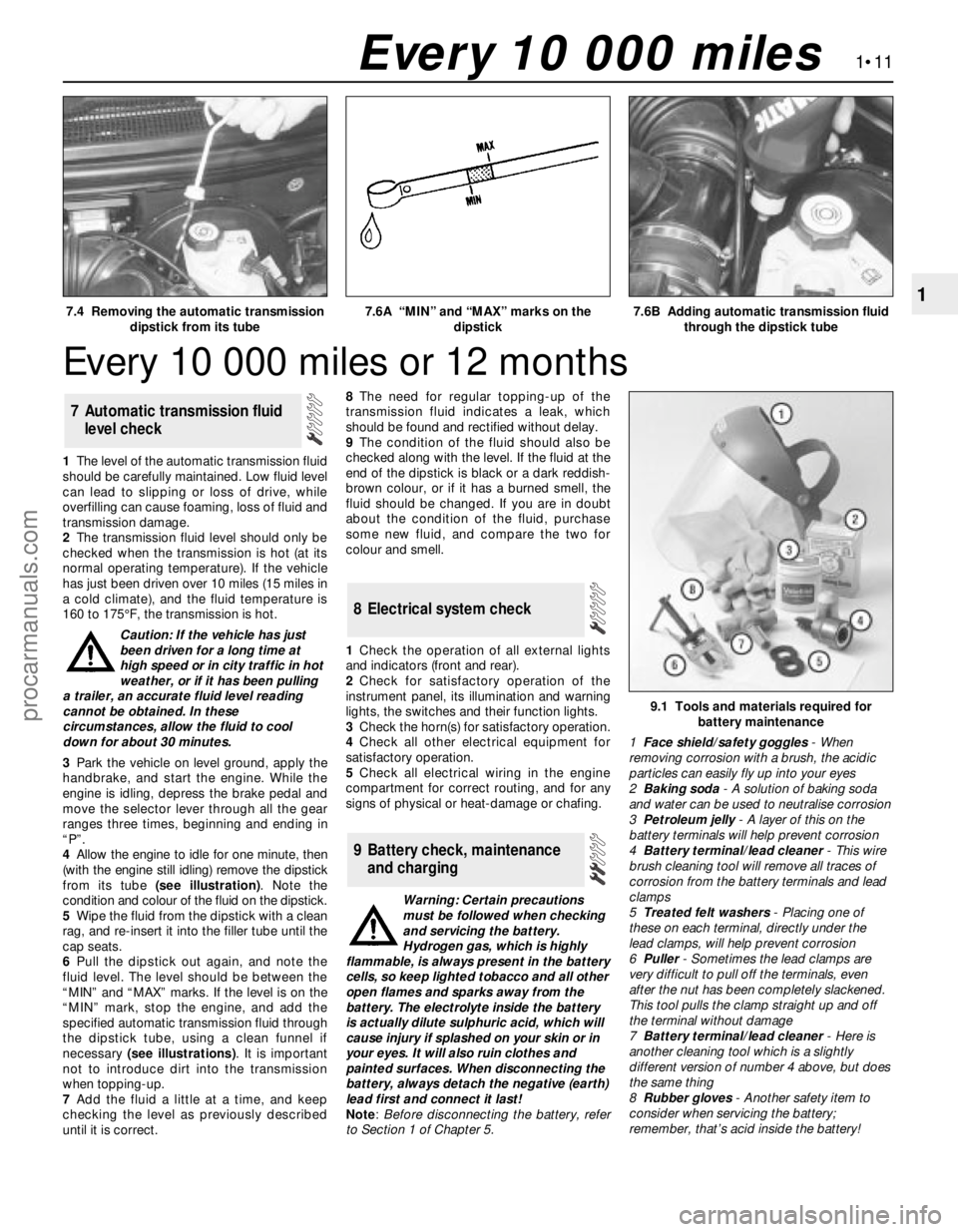
17.4 Removing the automatic transmission
dipstick from its tube7.6A “MIN” and “MAX” marks on the
dipstick7.6B Adding automatic transmission fluid
through the dipstick tube
Every 10 000 miles
1The level of the automatic transmission fluid
should be carefully maintained. Low fluid level
can lead to slipping or loss of drive, while
overfilling can cause foaming, loss of fluid and
transmission damage.
2The transmission fluid level should only be
checked when the transmission is hot (at its
normal operating temperature). If the vehicle
has just been driven over 10 miles (15 miles in
a cold climate), and the fluid temperature is
160 to 175°F, the transmission is hot.
Caution: If the vehicle has just
been driven for a long time at
high speed or in city traffic in hot
weather, or if it has been pulling
a trailer, an accurate fluid level reading
cannot be obtained. In these
circumstances, allow the fluid to cool
down for about 30 minutes.
3Park the vehicle on level ground, apply the
handbrake, and start the engine. While the
engine is idling, depress the brake pedal and
move the selector lever through all the gear
ranges three times, beginning and ending in
“P”.
4Allow the engine to idle for one minute, then
(with the engine still idling) remove the dipstick
from its tube (see illustration). Note the
condition and colour of the fluid on the dipstick.
5Wipe the fluid from the dipstick with a clean
rag, and re-insert it into the filler tube until the
cap seats.
6Pull the dipstick out again, and note the
fluid level. The level should be between the
“MIN” and “MAX” marks. If the level is on the
“MIN” mark, stop the engine, and add the
specified automatic transmission fluid through
the dipstick tube, using a clean funnel if
necessary (see illustrations). It is important
not to introduce dirt into the transmission
when topping-up.
7Add the fluid a little at a time, and keep
checking the level as previously described
until it is correct.8The need for regular topping-up of the
transmission fluid indicates a leak, which
should be found and rectified without delay.
9The condition of the fluid should also be
checked along with the level. If the fluid at the
end of the dipstick is black or a dark reddish-
brown colour, or if it has a burned smell, the
fluid should be changed. If you are in doubt
about the condition of the fluid, purchase
some new fluid, and compare the two for
colour and smell.
1Check the operation of all external lights
and indicators (front and rear).
2Check for satisfactory operation of the
instrument panel, its illumination and warning
lights, the switches and their function lights.
3Check the horn(s) for satisfactory operation.
4Check all other electrical equipment for
satisfactory operation.
5Check all electrical wiring in the engine
compartment for correct routing, and for any
signs of physical or heat-damage or chafing.
Warning: Certain precautions
must be followed when checking
and servicing the battery.
Hydrogen gas, which is highly
flammable, is always present in the battery
cells, so keep lighted tobacco and all other
open flames and sparks away from the
battery. The electrolyte inside the battery
is actually dilute sulphuric acid, which will
cause injury if splashed on your skin or in
your eyes. It will also ruin clothes and
painted surfaces. When disconnecting the
battery, always detach the negative (earth)
lead first and connect it last!
Note: Before disconnecting the battery, refer
to Section 1 of Chapter 5.
9 Battery check, maintenance
and charging
8 Electrical system check
7 Automatic transmission fluid
level check
9.1 Tools and materials required for
battery maintenance
1Face shield/safety goggles- When
removing corrosion with a brush, the acidic
particles can easily fly up into your eyes
2Baking soda- A solution of baking soda
and water can be used to neutralise corrosion
3Petroleum jelly- A layer of this on the
battery terminals will help prevent corrosion
4Battery terminal/lead cleaner- This wire
brush cleaning tool will remove all traces of
corrosion from the battery terminals and lead
clamps
5Treated felt washers- Placing one of
these on each terminal, directly under the
lead clamps, will help prevent corrosion
6Puller- Sometimes the lead clamps are
very difficult to pull off the terminals, even
after the nut has been completely slackened.
This tool pulls the clamp straight up and off
the terminal without damage
7Battery terminal/lead cleaner- Here is
another cleaning tool which is a slightly
different version of number 4 above, but does
the same thing
8Rubber gloves- Another safety item to
consider when servicing the battery;
remember, that’s acid inside the battery!
procarmanuals.com
Page 29 of 279
5Check all fluid reservoirs, filler caps, drain
plugs and fittings etc, looking for any signs of
leakage of oil, transmission and/or brake
hydraulic fluid, coolant and power steering
fluid. If the vehicle is regularly parked in the
same place, close inspection of the ground
underneath it will soon show any leaks; ignore
the puddle of water which will be left if the air
conditioning system is in use. As soon as a
leak is detected, its source must be traced
and rectified. Where oil has been leaking for
some time, it is usually necessary to use a
steam cleaner, pressure washer or similar, to
clean away the accumulated dirt, so that the
exact source of the leak can be identified.
Vacuum hoses
6It’s quite common for vacuum hoses,
especially those in the emissions system, to
be colour-coded, or to be identified by
coloured stripes moulded into them. Various
systems require hoses with different wall
thicknesses, collapse resistance and
temperature resistance. When renewing
hoses, be sure the new ones are made of the
same material.
7Often the only effective way to check a
hose is to remove it completely from the
vehicle. If more than one hose is removed, be
sure to label the hoses and fittings to ensure
correct installation.
8When checking vacuum hoses, be sure to
include any plastic T-fittings in the check.
Inspect the fittings for cracks, and check the
hose where it fits over the fitting for distortion,
which could cause leakage.
9A small piece of vacuum hose (quarter-inch
inside diameter) can be used as a
stethoscope to detect vacuum leaks. Hold
one end of the hose to your ear, and probe
around vacuum hoses and fittings, listening
for the “hissing” sound characteristic of a
vacuum leak.
Warning: When probing with the
vacuum hose stethoscope, be
very careful not to come into
contact with moving engine
components such as the auxiliary
drivebelt, radiator electric cooling fan, etc.
Fuel hoses
Warning: There are certain
precautions which must be taken
when inspecting or servicing fuel
system components. Work in a well-
ventilated area, and do not allow open
flames (cigarettes, appliance pilot lights,
etc.) or bare light bulbs near the work
area. Mop up any spills immediately, and
do not store fuel-soaked rags where they
could ignite.
10Check all fuel hoses for deterioration and
chafing. Check especially for cracks in areas
where the hose bends, and also just before
fittings, such as where a hose attaches to the
fuel filter.
11High-quality fuel line, usually identified by
the word “Fluoroelastomer” printed on thehose, should be used for fuel line renewal.
Never, under any circumstances, use
unreinforced vacuum line, clear plastic tubing
or water hose for fuel lines.
12Spring-type clamps are commonly used
on fuel lines. These clamps often lose their
tension over a period of time, and can be
“sprung” during removal. Replace all
spring-type clamps with screw clamps
whenever a hose is replaced.
Metal lines
13Sections of metal piping are often used
for fuel line between the fuel filter and the
engine. Check carefully to be sure the piping
has not been bent or crimped, and that cracks
have not started in the line.
14If a section of metal fuel line must be
renewed, only seamless steel piping should
be used, since copper and aluminium piping
don’t have the strength necessary to
withstand normal engine vibration.
15Check the metal brake lines where they
enter the master cylinder and ABS hydraulic
unit (if used) for cracks in the lines or loose
fittings. Any sign of brake fluid leakage calls
for an immediate and thorough inspection of
the brake system.
1With the vehicle parked on level ground,
apply the handbrake firmly and open the
bonnet. Using an inspection light or a small
electric torch, check all visible wiring within
and beneath the engine compartment.
2What you are looking for is wiring that is
obviously damaged by chafing against sharp
edges, or against moving suspension/
transmission components and/or the auxiliary
drivebelt, by being trapped or crushed
between carelessly-refitted components, or
melted by being forced into contact with the
hot engine castings, coolant pipes, etc. In
almost all cases, damage of this sort is
caused in the first instance by incorrect
routing on reassembly after previous work has
been carried out.
3Depending on the extent of the problem,
damaged wiring may be repaired by rejoining
the break or splicing-in a new length of wire,
using solder to ensure a good connection,
and remaking the insulation with adhesive
insulating tape or heat-shrink tubing, as
appropriate. If the damage is extensive, given
the implications for the vehicle’s future
reliability, the best long-term answer may well
be to renew that entire section of the loom,
however expensive this may appear.
4When the actual damage has been
repaired, ensure that the wiring loom is re-
routed correctly, so that it is clear of other
components, and not stretched or kinked, and
is secured out of harm’s way using the plastic
clips, guides and ties provided.
5Check all electrical connectors, ensuringthat they are clean, securely fastened, and
that each is locked by its plastic tabs or wire
clip, as appropriate. If any connector shows
external signs of corrosion (accumulations of
white or green deposits, or streaks of “rust”),
or if any is thought to be dirty, it must be
unplugged and cleaned using electrical
contact cleaner. If the connector pins are
severely corroded, the connector must be
renewed; note that this may mean the renewal
of that entire section of the loom - see your
local Ford dealer for details.
6If the cleaner completely removes the
corrosion to leave the connector in a
satisfactory condition, it would be wise to
pack the connector with a suitable material
which will exclude dirt and moisture,
preventing the corrosion from occurring
again; a Ford dealer may be able to
recommend a suitable product.
7Check the condition of the battery
connections - remake the connections or
renew the leads if a fault is found (see Chap-
ter 5). Use the same techniques to ensure that
all earth points in the engine compartment
provide good electrical contact through clean,
metal-to-metal joints, and that all are securely
fastened. (In addition to the earth connection
at the engine lifting eye, and that from the
transmission to the body/battery, there are
one or two earth points behind each headlight
assembly, and one below the power steering
fluid reservoir.)
8Refer to Section 31 for details of spark plug
(HT) lead checks.
Warning: The air conditioning
system is under high pressure.
Do not loosen any fittings or
remove any components until
after the system has been discharged. Air
conditioning refrigerant must be properly
discharged into an approved type of
container, at a dealer service department
or an automotive air conditioning repair
facility capable of handling R134a
refrigerant. Always wear eye protection
when disconnecting air conditioning
system fittings.
1The following maintenance checks should
be performed on a regular basis, to ensure
that the air conditioner continues to operate at
peak efficiency:
(a) Check the auxiliary drivebelt. If it’s worn
or deteriorated, renew it (see Section 11).
(b) Check the system hoses. Look for cracks,
bubbles, hard spots and deterioration.
Inspect the hoses and all fittings for oil
bubbles and seepage. If there’s any
evidence of wear, damage or leaks, renew
the hose(s).
(c) Inspect the condenser fins for leaves,
insects and other debris. Use a “fin
14 Air conditioning system
check
13 Engine compartment wiring
check
1•15
1
Every 10 000 miles
procarmanuals.com
Page 30 of 279
comb” or compressed air to clean the
condenser.
Warning: Wear eye protection
when using compressed air!
(d) Check that the drain tube from the front
of the evaporator is clear - note that it is
normal to have clear fluid (water) dripping
from this while the system is in operation,
to the extent that quite a large puddle can
be left under the vehicle when it is parked.
2It’s a good idea to operate the system forabout 30 minutes at least once a month,
particularly during the winter. Long term
non-use can cause hardening, and
subsequent failure, of the seals.
3Because of the complexity of the air
conditioning system and the special
equipment necessary to service it, in-depth
fault diagnosis and repairs are not included in
this manual. For more complete information
on the air conditioning system, refer to the
Haynes Automotive Heating and Air
Conditioning Manual.
4The most common cause of poor cooling is
simply a low system refrigerant charge. If a
noticeable drop in cool air output occurs, the
following quick check will help you determine
if the refrigerant level is low.
5Warm the engine up to normal operating
temperature.
6Place the air conditioning temperature
selector at the coldest setting, and put the
blower at the highest setting. Open the doors
- to make sure the air conditioning system
doesn’t cycle off as soon as it cools the
passenger compartment.
7With the compressor engaged - the clutch
will make an audible click, and the centre of
the clutch will rotate - feel the inlet and outlet
pipes at the compressor. One side should be
cold, and one hot. If there’s no perceptible
difference between the two pipes, there’s
something wrong with the compressor or the
system. It might be a low charge - it might be
something else. Take the vehicle to a dealer
service department or an automotive air
conditioning specialist.1Make sure that you have all the necessary
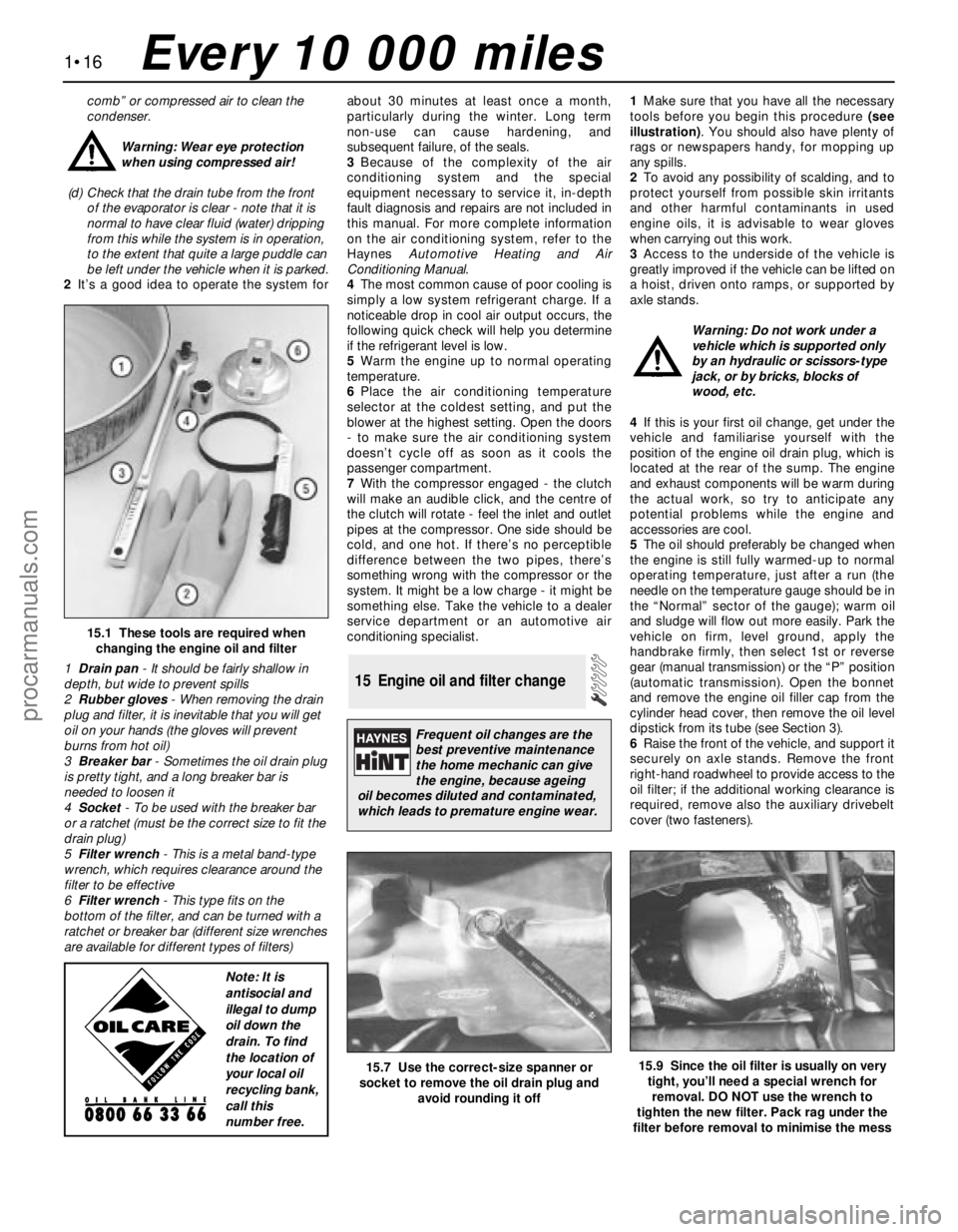
tools before you begin this procedure (see
illustration). You should also have plenty of
rags or newspapers handy, for mopping up
any spills.
2To avoid any possibility of scalding, and to
protect yourself from possible skin irritants
and other harmful contaminants in used
engine oils, it is advisable to wear gloves
when carrying out this work.
3Access to the underside of the vehicle is
greatly improved if the vehicle can be lifted on
a hoist, driven onto ramps, or supported by
axle stands.
Warning: Do not work under a
vehicle which is supported only
by an hydraulic or scissors-type
jack, or by bricks, blocks of
wood, etc.
4If this is your first oil change, get under the
vehicle and familiarise yourself with the
position of the engine oil drain plug, which is
located at the rear of the sump. The engine
and exhaust components will be warm during
the actual work, so try to anticipate any
potential problems while the engine and
accessories are cool.
5The oil should preferably be changed when
the engine is still fully warmed-up to normal
operating temperature, just after a run (the
needle on the temperature gauge should be in
the “Normal” sector of the gauge); warm oil
and sludge will flow out more easily. Park the
vehicle on firm, level ground, apply the
handbrake firmly, then select 1st or reverse
gear (manual transmission) or the “P” position
(automatic transmission). Open the bonnet
and remove the engine oil filler cap from the
cylinder head cover, then remove the oil level
dipstick from its tube (see Section 3).
6Raise the front of the vehicle, and support it
securely on axle stands. Remove the front
right-hand roadwheel to provide access to the
oil filter; if the additional working clearance is
required, remove also the auxiliary drivebelt
cover (two fasteners).
15 Engine oil and filter change
1•16
15.1 These tools are required when
changing the engine oil and filter
1Drain pan- It should be fairly shallow in
depth, but wide to prevent spills
2Rubber gloves- When removing the drain
plug and filter, it is inevitable that you will get
oil on your hands (the gloves will prevent
burns from hot oil)
3Breaker bar- Sometimes the oil drain plug
is pretty tight, and a long breaker bar is
needed to loosen it
4Socket- To be used with the breaker bar
or a ratchet (must be the correct size to fit the
drain plug)
5Filter wrench- This is a metal band-type
wrench, which requires clearance around the
filter to be effective
6Filter wrench- This type fits on the
bottom of the filter, and can be turned with a
ratchet or breaker bar (different size wrenches
are available for different types of filters)
15.7 Use the correct-size spanner or
socket to remove the oil drain plug and
avoid rounding it off15.9 Since the oil filter is usually on very
tight, you’ll need a special wrench for
removal. DO NOT use the wrench to
tighten the new filter. Pack rag under the
filter before removal to minimise the mess
Every 10 000 miles
Frequent oil changes are the
best preventive maintenance
the home mechanic can give
the engine, because ageing
oil becomes diluted and contaminated,
which leads to premature engine wear.
Note: It is
antisocial and
illegal to dump
oil down the
drain. To find
the location of
your local oil
recycling bank,
call this
number free.
procarmanuals.com
Page 32 of 279
of these components will cause loss of
lubricant, together with dirt and water entry,
resulting in rapid deterioration of the balljoints
or steering gear.
3Check the power-assisted steering fluid
hoses for chafing or deterioration, and the
pipe and hose unions for fluid leaks. Also
check for signs of fluid leakage under
pressure from the steering gear rubber
gaiters, which would indicate failed fluid seals
within the steering gear.
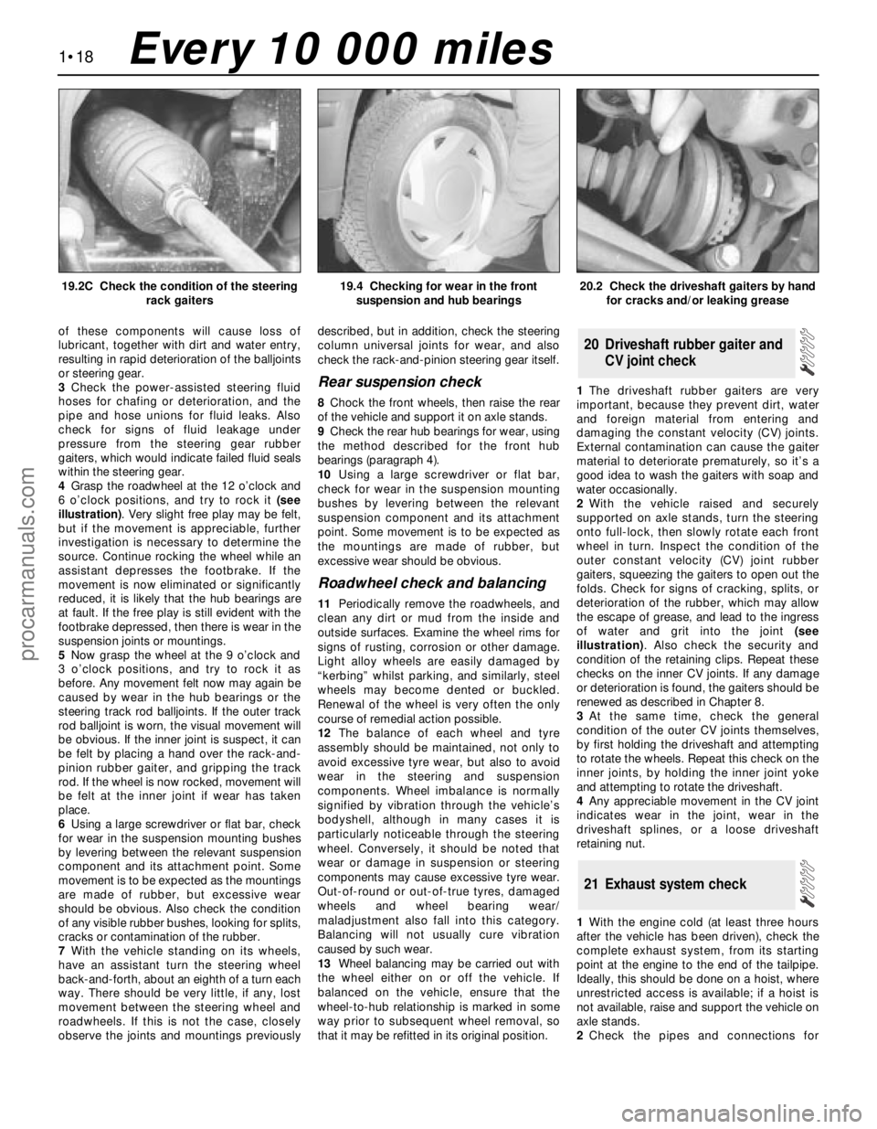
4Grasp the roadwheel at the 12 o’clock and
6 o’clock positions, and try to rock it (see
illustration). Very slight free play may be felt,
but if the movement is appreciable, further
investigation is necessary to determine the
source. Continue rocking the wheel while an
assistant depresses the footbrake. If the
movement is now eliminated or significantly
reduced, it is likely that the hub bearings are
at fault. If the free play is still evident with the
footbrake depressed, then there is wear in the
suspension joints or mountings.
5Now grasp the wheel at the 9 o’clock and
3 o’clock positions, and try to rock it as
before. Any movement felt now may again be
caused by wear in the hub bearings or the
steering track rod balljoints. If the outer track
rod balljoint is worn, the visual movement will
be obvious. If the inner joint is suspect, it can
be felt by placing a hand over the rack-and-
pinion rubber gaiter, and gripping the track
rod. If the wheel is now rocked, movement will
be felt at the inner joint if wear has taken
place.
6Using a large screwdriver or flat bar, check
for wear in the suspension mounting bushes
by levering between the relevant suspension
component and its attachment point. Some
movement is to be expected as the mountings
are made of rubber, but excessive wear
should be obvious. Also check the condition
of any visible rubber bushes, looking for splits,
cracks or contamination of the rubber.
7With the vehicle standing on its wheels,
have an assistant turn the steering wheel
back-and-forth, about an eighth of a turn each
way. There should be very little, if any, lost
movement between the steering wheel and
roadwheels. If this is not the case, closely
observe the joints and mountings previouslydescribed, but in addition, check the steering
column universal joints for wear, and also
check the rack-and-pinion steering gear itself.
Rear suspension check
8Chock the front wheels, then raise the rear
of the vehicle and support it on axle stands.
9Check the rear hub bearings for wear, using
the method described for the front hub
bearings (paragraph 4).
10Using a large screwdriver or flat bar,
check for wear in the suspension mounting
bushes by levering between the relevant
suspension component and its attachment
point. Some movement is to be expected as
the mountings are made of rubber, but
excessive wear should be obvious.
Roadwheel check and balancing
11Periodically remove the roadwheels, and
clean any dirt or mud from the inside and
outside surfaces. Examine the wheel rims for
signs of rusting, corrosion or other damage.
Light alloy wheels are easily damaged by
“kerbing” whilst parking, and similarly, steel
wheels may become dented or buckled.
Renewal of the wheel is very often the only
course of remedial action possible.
12The balance of each wheel and tyre
assembly should be maintained, not only to
avoid excessive tyre wear, but also to avoid
wear in the steering and suspension
components. Wheel imbalance is normally
signified by vibration through the vehicle’s
bodyshell, although in many cases it is
particularly noticeable through the steering
wheel. Conversely, it should be noted that
wear or damage in suspension or steering
components may cause excessive tyre wear.
Out-of-round or out-of-true tyres, damaged
wheels and wheel bearing wear/
maladjustment also fall into this category.
Balancing will not usually cure vibration
caused by such wear.
13Wheel balancing may be carried out with
the wheel either on or off the vehicle. If
balanced on the vehicle, ensure that the
wheel-to-hub relationship is marked in some
way prior to subsequent wheel removal, so
that it may be refitted in its original position.1The driveshaft rubber gaiters are very
important, because they prevent dirt, water
and foreign material from entering and
damaging the constant velocity (CV) joints.
External contamination can cause the gaiter
material to deteriorate prematurely, so it’s a
good idea to wash the gaiters with soap and
water occasionally.
2With the vehicle raised and securely
supported on axle stands, turn the steering
onto full-lock, then slowly rotate each front
wheel in turn. Inspect the condition of the
outer constant velocity (CV) joint rubber
gaiters, squeezing the gaiters to open out the
folds. Check for signs of cracking, splits, or
deterioration of the rubber, which may allow
the escape of grease, and lead to the ingress
of water and grit into the joint (see
illustration). Also check the security and
condition of the retaining clips. Repeat these
checks on the inner CV joints. If any damage
or deterioration is found, the gaiters should be
renewed as described in Chapter 8.
3At the same time, check the general
condition of the outer CV joints themselves,
by first holding the driveshaft and attempting
to rotate the wheels. Repeat this check on the
inner joints, by holding the inner joint yoke
and attempting to rotate the driveshaft.
4Any appreciable movement in the CV joint
indicates wear in the joint, wear in the
driveshaft splines, or a loose driveshaft
retaining nut.
1With the engine cold (at least three hours
after the vehicle has been driven), check the
complete exhaust system, from its starting
point at the engine to the end of the tailpipe.
Ideally, this should be done on a hoist, where
unrestricted access is available; if a hoist is
not available, raise and support the vehicle on
axle stands.
2Check the pipes and connections for
21 Exhaust system check
20 Driveshaft rubber gaiter and
CV joint check
1•18
19.2C Check the condition of the steering
rack gaiters19.4 Checking for wear in the front
suspension and hub bearings20.2 Check the driveshaft gaiters by hand
for cracks and/or leaking grease
Every 10 000 miles
procarmanuals.com
Page 33 of 279
evidence of leaks, severe corrosion, or
damage. Make sure that all brackets and
rubber mountings are in good condition, and
tight; if any of the mountings are to be
renewed, ensure that the replacements are of
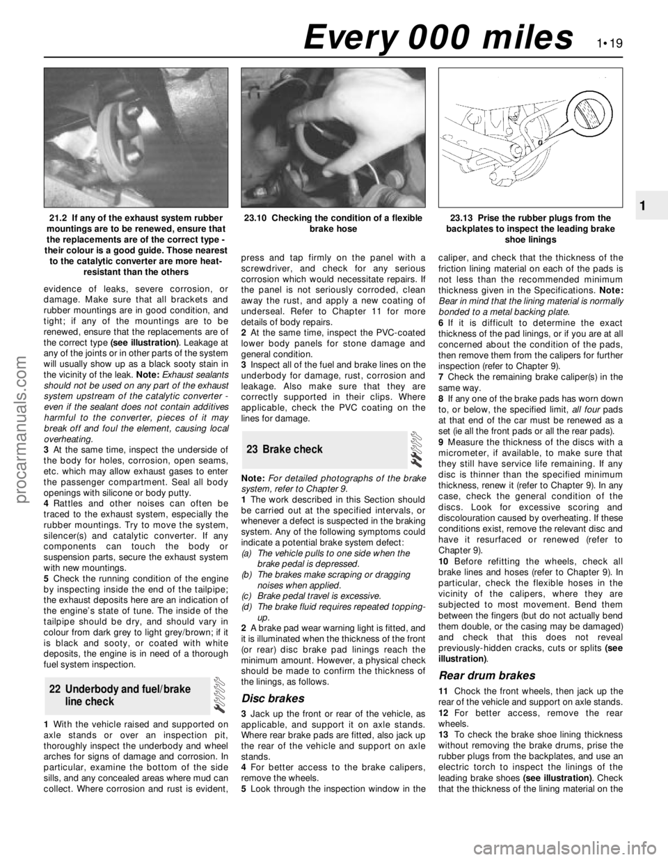
the correct type (see illustration). Leakage at
any of the joints or in other parts of the system
will usually show up as a black sooty stain in
the vicinity of the leak. Note:Exhaust sealants
should not be used on any part of the exhaust
system upstream of the catalytic converter -
even if the sealant does not contain additives
harmful to the converter, pieces of it may
break off and foul the element, causing local
overheating.
3At the same time, inspect the underside of
the body for holes, corrosion, open seams,
etc. which may allow exhaust gases to enter
the passenger compartment. Seal all body
openings with silicone or body putty.
4Rattles and other noises can often be
traced to the exhaust system, especially the
rubber mountings. Try to move the system,
silencer(s) and catalytic converter. If any
components can touch the body or
suspension parts, secure the exhaust system
with new mountings.
5Check the running condition of the engine
by inspecting inside the end of the tailpipe;
the exhaust deposits here are an indication of
the engine’s state of tune. The inside of the
tailpipe should be dry, and should vary in
colour from dark grey to light grey/brown; if it
is black and sooty, or coated with white
deposits, the engine is in need of a thorough
fuel system inspection.
1With the vehicle raised and supported on
axle stands or over an inspection pit,
thoroughly inspect the underbody and wheel
arches for signs of damage and corrosion. In
particular, examine the bottom of the side
sills, and any concealed areas where mud can
collect. Where corrosion and rust is evident,press and tap firmly on the panel with a
screwdriver, and check for any serious
corrosion which would necessitate repairs. If
the panel is not seriously corroded, clean
away the rust, and apply a new coating of
underseal. Refer to Chapter 11 for more
details of body repairs.
2At the same time, inspect the PVC-coated
lower body panels for stone damage and
general condition.
3Inspect all of the fuel and brake lines on the
underbody for damage, rust, corrosion and
leakage. Also make sure that they are
correctly supported in their clips. Where
applicable, check the PVC coating on the
lines for damage.
Note:For detailed photographs of the brake
system, refer to Chapter 9.
1The work described in this Section should
be carried out at the specified intervals, or
whenever a defect is suspected in the braking
system. Any of the following symptoms could
indicate a potential brake system defect:
(a) The vehicle pulls to one side when the
brake pedal is depressed.
(b) The brakes make scraping or dragging
noises when applied.
(c) Brake pedal travel is excessive.
(d) The brake fluid requires repeated topping-
up.
2A brake pad wear warning light is fitted, and
it is illuminated when the thickness of the front
(or rear) disc brake pad linings reach the
minimum amount. However, a physical check
should be made to confirm the thickness of
the linings, as follows.
Disc brakes
3Jack up the front or rear of the vehicle, as
applicable, and support it on axle stands.
Where rear brake pads are fitted, also jack up
the rear of the vehicle and support on axle
stands.
4For better access to the brake calipers,
remove the wheels.
5Look through the inspection window in thecaliper, and check that the thickness of the
friction lining material on each of the pads is
not less than the recommended minimum
thickness given in the Specifications. Note:
Bear in mind that the lining material is normally
bonded to a metal backing plate.
6If it is difficult to determine the exact
thickness of the pad linings, or if you are at all
concerned about the condition of the pads,
then remove them from the calipers for further
inspection (refer to Chapter 9).
7Check the remaining brake caliper(s) in the
same way.
8If any one of the brake pads has worn down
to, or below, the specified limit, all fourpads
at that end of the car must be renewed as a
set (ie all the front pads or all the rear pads).
9Measure the thickness of the discs with a
micrometer, if available, to make sure that
they still have service life remaining. If any
disc is thinner than the specified minimum
thickness, renew it (refer to Chapter 9). In any
case, check the general condition of the
discs. Look for excessive scoring and
discolouration caused by overheating. If these
conditions exist, remove the relevant disc and
have it resurfaced or renewed (refer to
Chapter 9).
10Before refitting the wheels, check all
brake lines and hoses (refer to Chapter 9). In
particular, check the flexible hoses in the
vicinity of the calipers, where they are
subjected to most movement. Bend them
between the fingers (but do not actually bend
them double, or the casing may be damaged)
and check that this does not reveal
previously-hidden cracks, cuts or splits (see
illustration).
Rear drum brakes
11Chock the front wheels, then jack up the
rear of the vehicle and support on axle stands.
12For better access, remove the rear
wheels.
13To check the brake shoe lining thickness
without removing the brake drums, prise the
rubber plugs from the backplates, and use an
electric torch to inspect the linings of the
leading brake shoes (see illustration). Check
that the thickness of the lining material on the
23 Brake check
22 Underbody and fuel/brake
line check
1•19
121.2 If any of the exhaust system rubber
mountings are to be renewed, ensure that
the replacements are of the correct type -
their colour is a good guide. Those nearest
to the catalytic converter are more heat-
resistant than the others23.10 Checking the condition of a flexible
brake hose23.13 Prise the rubber plugs from the
backplates to inspect the leading brake
shoe linings
Every 000 miles
procarmanuals.com
Page 34 of 279
brake shoes is not less than the
recommendation given in the Specifications.
14If it is difficult to determine the exact
thickness of the brake shoe linings, or if you
are at all concerned about the condition of the
shoes, then remove the rear drums for a more
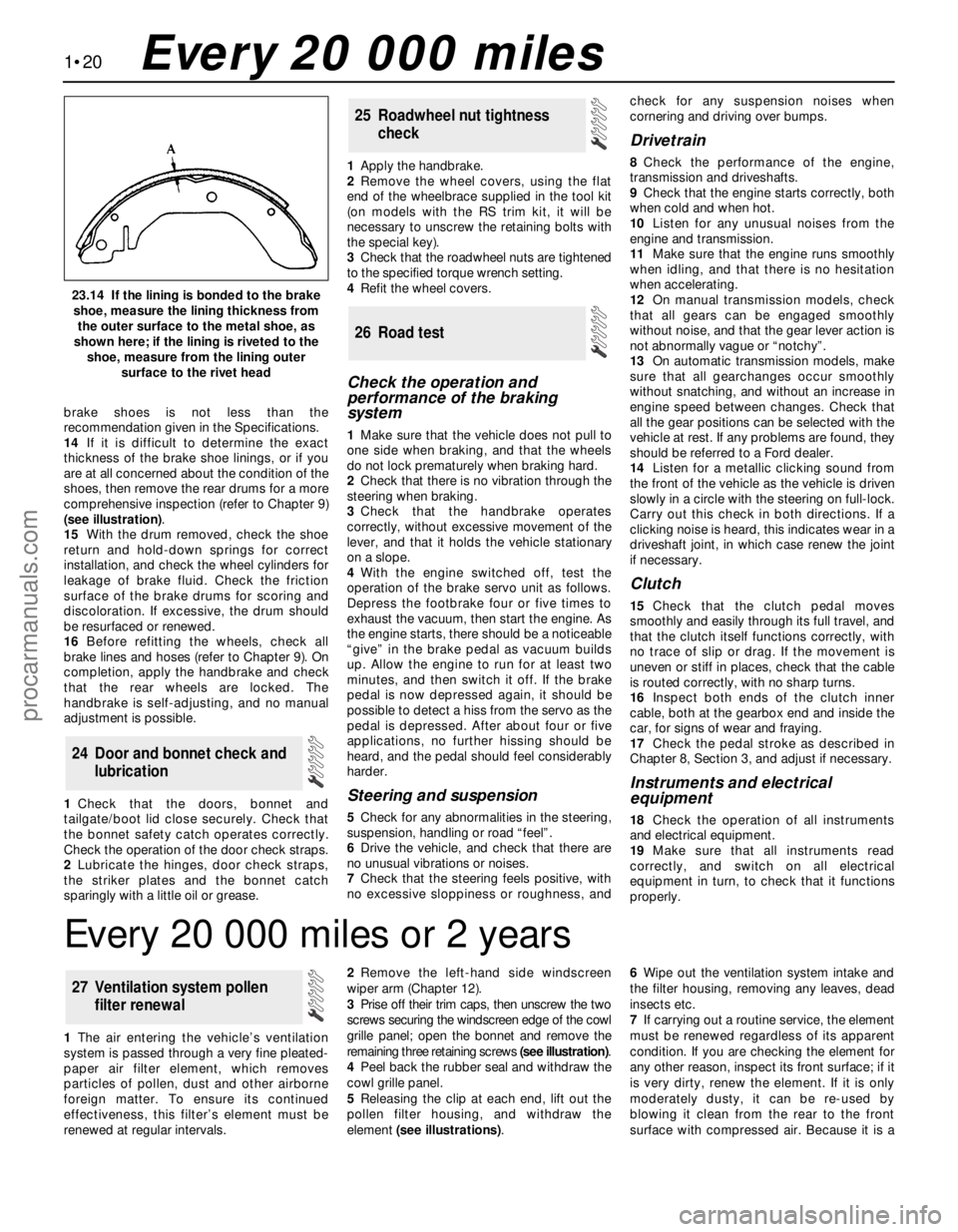
comprehensive inspection (refer to Chapter 9)
(see illustration).
15With the drum removed, check the shoe
return and hold-down springs for correct
installation, and check the wheel cylinders for
leakage of brake fluid. Check the friction
surface of the brake drums for scoring and
discoloration. If excessive, the drum should
be resurfaced or renewed.
16Before refitting the wheels, check all
brake lines and hoses (refer to Chapter 9). On
completion, apply the handbrake and check
that the rear wheels are locked. The
handbrake is self-adjusting, and no manual
adjustment is possible.
1Check that the doors, bonnet and
tailgate/boot lid close securely. Check that
the bonnet safety catch operates correctly.
Check the operation of the door check straps.
2Lubricate the hinges, door check straps,
the striker plates and the bonnet catch
sparingly with a little oil or grease.1Apply the handbrake.
2Remove the wheel covers, using the flat
end of the wheelbrace supplied in the tool kit
(on models with the RS trim kit, it will be
necessary to unscrew the retaining bolts with
the special key).
3Check that the roadwheel nuts are tightened
to the specified torque wrench setting.
4Refit the wheel covers.
Check the operation and
performance of the braking
system
1Make sure that the vehicle does not pull to
one side when braking, and that the wheels
do not lock prematurely when braking hard.
2Check that there is no vibration through the
steering when braking.
3Check that the handbrake operates
correctly, without excessive movement of the
lever, and that it holds the vehicle stationary
on a slope.
4With the engine switched off, test the
operation of the brake servo unit as follows.
Depress the footbrake four or five times to
exhaust the vacuum, then start the engine. As
the engine starts, there should be a noticeable
“give” in the brake pedal as vacuum builds
up. Allow the engine to run for at least two
minutes, and then switch it off. If the brake
pedal is now depressed again, it should be
possible to detect a hiss from the servo as the
pedal is depressed. After about four or five
applications, no further hissing should be
heard, and the pedal should feel considerably
harder.
Steering and suspension
5Check for any abnormalities in the steering,
suspension, handling or road “feel”.
6Drive the vehicle, and check that there are
no unusual vibrations or noises.
7Check that the steering feels positive, with
no excessive sloppiness or roughness, andcheck for any suspension noises when
cornering and driving over bumps.
Drivetrain
8Check the performance of the engine,
transmission and driveshafts.
9Check that the engine starts correctly, both
when cold and when hot.
10Listen for any unusual noises from the
engine and transmission.
11Make sure that the engine runs smoothly
when idling, and that there is no hesitation
when accelerating.
12On manual transmission models, check
that all gears can be engaged smoothly
without noise, and that the gear lever action is
not abnormally vague or “notchy”.
13On automatic transmission models, make
sure that all gearchanges occur smoothly
without snatching, and without an increase in
engine speed between changes. Check that
all the gear positions can be selected with the
vehicle at rest. If any problems are found, they
should be referred to a Ford dealer.
14Listen for a metallic clicking sound from
the front of the vehicle as the vehicle is driven
slowly in a circle with the steering on full-lock.
Carry out this check in both directions. If a
clicking noise is heard, this indicates wear in a
driveshaft joint, in which case renew the joint
if necessary.
Clutch
15Check that the clutch pedal moves
smoothly and easily through its full travel, and
that the clutch itself functions correctly, with
no trace of slip or drag. If the movement is
uneven or stiff in places, check that the cable
is routed correctly, with no sharp turns.
16Inspect both ends of the clutch inner
cable, both at the gearbox end and inside the
car, for signs of wear and fraying.
17Check the pedal stroke as described in
Chapter 8, Section 3, and adjust if necessary.
Instruments and electrical
equipment
18Check the operation of all instruments
and electrical equipment.
19Make sure that all instruments read
correctly, and switch on all electrical
equipment in turn, to check that it functions
properly.
26 Road test
25 Roadwheel nut tightness
check
24 Door and bonnet check and
lubrication
1•20
23.14 If the lining is bonded to the brake
shoe, measure the lining thickness from
the outer surface to the metal shoe, as
shown here; if the lining is riveted to the
shoe, measure from the lining outer
surface to the rivet head
Every 20 000 miles
Every 20 000 miles or 2 years
1The air entering the vehicle’s ventilation
system is passed through a very fine pleated-
paper air filter element, which removes
particles of pollen, dust and other airborne
foreign matter. To ensure its continued
effectiveness, this filter’s element must be
renewed at regular intervals.2Remove the left-hand side windscreen
wiper arm (Chapter 12).
3Prise off their trim caps, then unscrew the two
screws securing the windscreen edge of the cowl
grille panel; open the bonnet and remove the
remaining three retaining screws (see illustration).
4Peel back the rubber seal and withdraw the
cowl grille panel.
5Releasing the clip at each end, lift out the
pollen filter housing, and withdraw the
element (see illustrations).6Wipe out the ventilation system intake and
the filter housing, removing any leaves, dead
insects etc.
7If carrying out a routine service, the element
must be renewed regardless of its apparent
condition. If you are checking the element for
any other reason, inspect its front surface; if it
is very dirty, renew the element. If it is only
moderately dusty, it can be re-used by
blowing it clean from the rear to the front
surface with compressed air. Because it is a
27 Ventilation system pollen
filter renewal
procarmanuals.com