1993 FORD MONDEO brake fluid
[x] Cancel search: brake fluidPage 126 of 279
6With the drum in position, refit the wheel,
then carry out the renewal procedure on the
remaining rear brake.
7Lower the vehicle to the ground, and
tighten the wheel nuts.
8Depress the brake pedal several times, in
order to operate the self-adjusting mechanism
and set the shoes at their normal operating
position.
9Make several forward and reverse stops,
and operate the handbrake fully two or three
times. Give the vehicle a road test, to make
sure that the brakes are functioning correctly,
and to bed-in the new linings to the contours
of the disc. Remember that the new linings
will not give full braking efficiency until they
have bedded-in.
Note:Before starting work, check on the
availability of parts (overhaul kit of seals). Also
bear in mind that if the brake shoes have been
contaminated by fluid leaking from the wheel
cylinder, they must be renewed. In principle,
the shoes on BOTH sides of the vehicle must
be renewed, even if they are only
contaminated on one side.
Removal
1Remove the brake drum as described in
Section 5.
2Minimise fluid loss either by removing the
master cylinder reservoir cap, and then
tightening it down onto a piece of polythene
to obtain an airtight seal, or by using a brake
hose clamp, a G-clamp, or similar tool, to
clamp the flexible hose at the nearest
convenient point to the wheel cylinder.
3Pull the brake shoes apart at their top ends,
so that they are just clear of the wheel
cylinder. The automatic adjuster will hold the
shoes in this position, so that the cylinder can
be withdrawn.
4Wipe away all traces of dirt around the
hydraulic union at the rear of the wheel
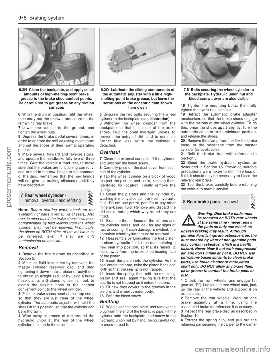
cylinder, then undo the union nut.5Unscrew the two bolts securing the wheel
cylinder to the backplate (see illustration).
6Withdraw the wheel cylinder from the
backplate so that it is clear of the brake
shoes. Plug the open hydraulic unions, to
prevent the entry of dirt, and to minimise
further fluid loss whilst the cylinder is
detached.
Overhaul
7Clean the external surfaces of the cylinder,
and unscrew the bleed screw.
8Carefully prise off the dust cover from each
end of the cylinder.
9Tap the wheel cylinder on a block of wood
to eject the pistons and seals, keeping them
identified for location. Finally remove the
spring.
10Clean the pistons and the cylinder by
washing in methylated spirit or fresh hydraulic
fluid. Do not use petrol, paraffin or any other
mineral-based fluid. Remove and discard the
old seals, noting which way round they are
fitted.
11Examine the surfaces of the pistons and
the cylinder bores, and look for any signs of
rust or scoring. If such damage is evident, the
complete wheel cylinder must be renewed.
12Reassemble by lubricating the first piston
in clean hydraulic fluid, then manipulating a
new seal into position, so that its raised lip
faces away from the brake shoe bearing face
of the piston.
13Insert the piston into the cylinder. As the
seal enters the bore, twist the piston back and
forth so that the seal lip is not trapped.
14Insert the spring, then refit the remaining
piston and seal, again making sure that the
seal lip is not trapped as it enters the bore.
15Fit new dust covers to the grooves in the
pistons and wheel cylinder body.
16Refit the bleed screw.
Refitting
17Wipe clean the backplate, and remove the
plug from the end of the hydraulic pipe. Fit the
cylinder onto the backplate, and screw in the
hydraulic union nut by hand, being careful not
to cross-thread it.18Tighten the mounting bolts, then fully
tighten the hydraulic union nut.
19Retract the automatic brake adjuster
mechanism, so that the brake shoes engage
with the pistons of the wheel cylinder. To do
this, prise the shoes apart slightly, turn the
automatic adjuster to its minimum position,
and release the shoes.
20Remove the clamp from the flexible brake
hose, or the polythene from the master
cylinder (as applicable).
21Refit the brake drum with reference to
Section 5.
22Bleed the brake hydraulic system as
described in Section 15. Providing suitable
precautions were taken to minimise loss of
fluid, it should only be necessary to bleed the
relevant rear brake.
23Test the brakes carefully before returning
the vehicle to normal service.
Warning: Disc brake pads must
be renewed on BOTH rear wheels
at the same time - never renew
the pads on only one wheel, as
uneven braking may result. Although
genuine Ford linings are asbestos-free, the
dust created by wear of non-genuine pads
may contain asbestos, which is a health
hazard. Never blow it out with compressed
air, and don’t inhale any of it. DO NOT use
petroleum-based solvents to clean brake
parts; use brake cleaner or methylated
spirit only. DO NOT allow any brake fluid,
oil or grease to contact the brake pads or
disc.
1Chock the front wheels, and engage 1st
gear (or “P”). Loosen the rear wheel nuts, jack
up the rear of the vehicle and support it on
axle stands.
2Remove the rear wheels. Work on one
brake assembly at a time, using the
assembled brake for reference if necessary.
3Inspect the rear brake disc as described in
Section 10.
4Extract the spring clip, and pull out the
retaining pin securing the caliper to the carrier
8 Rear brake pads - renewal
7 Rear wheel cylinder -
removal, overhaul and refitting
9•8 Braking system
6.2N Clean the backplate, and apply small
amounts of high-melting-point brake
grease to the brake shoe contact points.
Be careful not to get grease on any friction
surfaces6.2O Lubricate the sliding components of
the automatic adjuster with a little high-
melting-point brake grease, but leave the
serrations on the eccentric cam shown
here clean7.5 Bolts securing the wheel cylinder to
the backplate. Hydraulic union nut and
bleed screw cover are also visible
procarmanuals.com
Page 127 of 279
bracket. Note that on Saloon and Hatchback
models, the pin is at the bottom of the caliper,
whereas on Estate models, it is at the top.
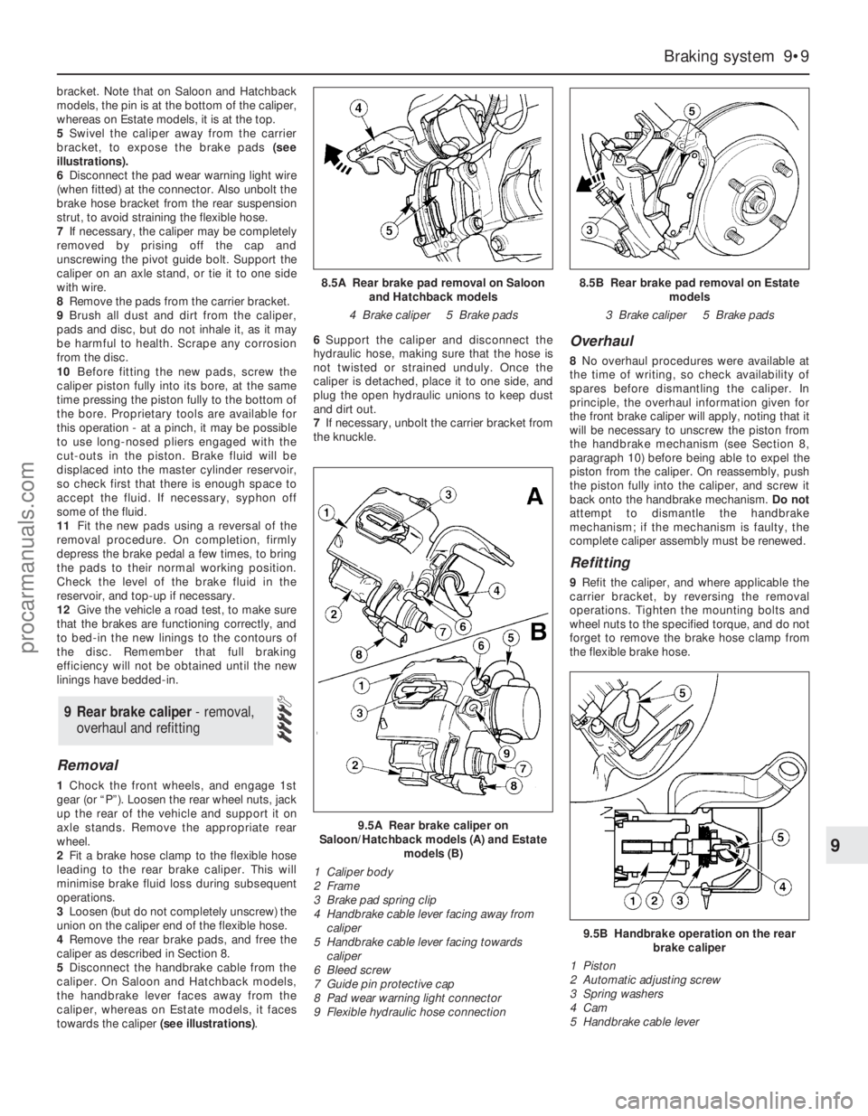
5Swivel the caliper away from the carrier
bracket, to expose the brake pads (see
illustrations).
6Disconnect the pad wear warning light wire
(when fitted) at the connector. Also unbolt the
brake hose bracket from the rear suspension
strut, to avoid straining the flexible hose.
7If necessary, the caliper may be completely
removed by prising off the cap and
unscrewing the pivot guide bolt. Support the
caliper on an axle stand, or tie it to one side
with wire.
8Remove the pads from the carrier bracket.
9Brush all dust and dirt from the caliper,
pads and disc, but do not inhale it, as it may
be harmful to health. Scrape any corrosion
from the disc.
10Before fitting the new pads, screw the
caliper piston fully into its bore, at the same
time pressing the piston fully to the bottom of
the bore. Proprietary tools are available for
this operation - at a pinch, it may be possible
to use long-nosed pliers engaged with the
cut-outs in the piston. Brake fluid will be
displaced into the master cylinder reservoir,
so check first that there is enough space to
accept the fluid. If necessary, syphon off
some of the fluid.
11Fit the new pads using a reversal of the
removal procedure. On completion, firmly
depress the brake pedal a few times, to bring
the pads to their normal working position.
Check the level of the brake fluid in the
reservoir, and top-up if necessary.
12Give the vehicle a road test, to make sure
that the brakes are functioning correctly, and
to bed-in the new linings to the contours of
the disc. Remember that full braking
efficiency will not be obtained until the new
linings have bedded-in.
Removal
1Chock the front wheels, and engage 1st
gear (or “P”). Loosen the rear wheel nuts, jack
up the rear of the vehicle and support it on
axle stands. Remove the appropriate rear
wheel.
2Fit a brake hose clamp to the flexible hose
leading to the rear brake caliper. This will
minimise brake fluid loss during subsequent
operations.
3Loosen (but do not completely unscrew) the
union on the caliper end of the flexible hose.
4Remove the rear brake pads, and free the
caliper as described in Section 8.
5Disconnect the handbrake cable from the
caliper. On Saloon and Hatchback models,
the handbrake lever faces away from the
caliper, whereas on Estate models, it faces
towards the caliper (see illustrations).6Support the caliper and disconnect the
hydraulic hose, making sure that the hose is
not twisted or strained unduly. Once the
caliper is detached, place it to one side, and
plug the open hydraulic unions to keep dust
and dirt out.
7If necessary, unbolt the carrier bracket from
the knuckle.
Overhaul
8No overhaul procedures were available at
the time of writing, so check availability of
spares before dismantling the caliper. In
principle, the overhaul information given for
the front brake caliper will apply, noting that it
will be necessary to unscrew the piston from
the handbrake mechanism (see Section 8,
paragraph 10) before being able to expel the
piston from the caliper. On reassembly, push
the piston fully into the caliper, and screw it
back onto the handbrake mechanism. Do not
attempt to dismantle the handbrake
mechanism; if the mechanism is faulty, the
complete caliper assembly must be renewed.
Refitting
9Refit the caliper, and where applicable the
carrier bracket, by reversing the removal
operations. Tighten the mounting bolts and
wheel nuts to the specified torque, and do not
forget to remove the brake hose clamp from
the flexible brake hose.
9 Rear brake caliper - removal,
overhaul and refitting
Braking system 9•9
9
9.5A Rear brake caliper on
Saloon/Hatchback models (A) and Estate
models (B)
1 Caliper body
2 Frame
3 Brake pad spring clip
4 Handbrake cable lever facing away from
caliper
5 Handbrake cable lever facing towards
caliper
6 Bleed screw
7 Guide pin protective cap
8 Pad wear warning light connector
9 Flexible hydraulic hose connection
9.5B Handbrake operation on the rear
brake caliper
1 Piston
2 Automatic adjusting screw
3 Spring washers
4 Cam
5 Handbrake cable lever
8.5A Rear brake pad removal on Saloon
and Hatchback models
4 Brake caliper 5 Brake pads8.5B Rear brake pad removal on Estate
models
3 Brake caliper 5 Brake pads
procarmanuals.com
Page 128 of 279
10Bleed the brake circuit according to the
procedure given in Section 15. Make sure
there are no leaks from the hose connections.
Test the brakes carefully before returning the
vehicle to normal service.
Refer to Section 4 (front disc inspection).
Once the rear caliper is removed, the
procedure is the same.
Removal
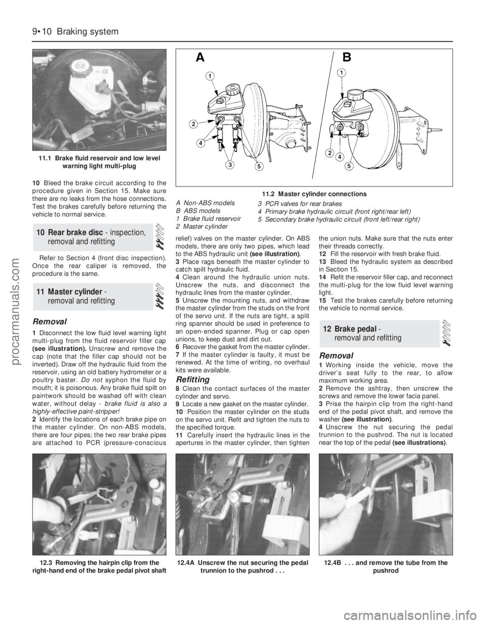
1Disconnect the low fluid level warning light
multi-plug from the fluid reservoir filler cap
(see illustration).Unscrew and remove the
cap (note that the filler cap should not be
inverted). Draw off the hydraulic fluid from the
reservoir, using an old battery hydrometer or a
poultry baster. Do notsyphon the fluid by
mouth; it is poisonous. Any brake fluid spilt on
paintwork should be washed off with clean
water, without delay - brake fluid is also a
highly-effective paint-stripper!
2Identify the locations of each brake pipe on
the master cylinder. On non-ABS models,
there are four pipes; the two rear brake pipes
are attached to PCR (pressure-consciousrelief) valves on the master cylinder. On ABS
models, there are only two pipes, which lead
to the ABS hydraulic unit (see illustration).
3Place rags beneath the master cylinder to
catch spilt hydraulic fluid.
4Clean around the hydraulic union nuts.
Unscrew the nuts, and disconnect the
hydraulic lines from the master cylinder.
5Unscrew the mounting nuts, and withdraw
the master cylinder from the studs on the front
of the servo unit. If the nuts are tight, a split
ring spanner should be used in preference to
an open-ended spanner. Plug or cap open
unions, to keep dust and dirt out.
6Recover the gasket from the master cylinder.
7If the master cylinder is faulty, it must be
renewed. At the time of writing, no overhaul
kits were available.
Refitting
8Clean the contact surfaces of the master
cylinder and servo.
9Locate a new gasket on the master cylinder.
10Position the master cylinder on the studs
on the servo unit. Refit and tighten the nuts to
the specified torque.
11Carefully insert the hydraulic lines in the
apertures in the master cylinder, then tightenthe union nuts. Make sure that the nuts enter
their threads correctly.
12Fill the reservoir with fresh brake fluid.
13Bleed the hydraulic system as described
in Section 15.
14Refit the reservoir filler cap, and reconnect
the multi-plug for the low fluid level warning
light.
15Test the brakes carefully before returning
the vehicle to normal service.
Removal
1Working inside the vehicle, move the
driver’s seat fully to the rear, to allow
maximum working area.
2Remove the ashtray, then unscrew the
screws and remove the lower facia panel.
3Prise the hairpin clip from the right-hand
end of the pedal pivot shaft, and remove the
washer (see illustration).
4Unscrew the nut securing the pedal
trunnion to the pushrod. The nut is located
near the top of the pedal (see illustrations).
12 Brake pedal-
removal and refitting
11 Master cylinder -
removal and refitting
10 Rear brake disc - inspection,
removal and refitting
9•10 Braking system
11.1 Brake fluid reservoir and low level
warning light multi-plug
11.2 Master cylinder connections
A Non-ABS models
B ABS models
1 Brake fluid reservoir
2 Master cylinder3 PCR valves for rear brakes
4 Primary brake hydraulic circuit (front right/rear left)
5 Secondary brake hydraulic circuit (front left/rear right)
12.3 Removing the hairpin clip from the
right-hand end of the brake pedal pivot shaft12.4A Unscrew the nut securing the pedal
trunnion to the pushrod . . .12.4B . . . and remove the tube from the
pushrod
procarmanuals.com
Page 129 of 279
5Press the pedal pivot shaft to the left,
through the mounting bracket, just far enough
to allow the pedal to be withdrawn. On
manual transmission models, leave the blue
nylon spacer (located between the clutch and
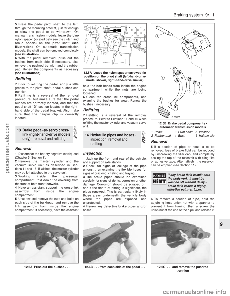
brake pedals) on the pivot shaft (see
illustration). On automatic transmission
models, the shaft can be removed completely
(see illustration).
6With the pedal removed, prise out the
bushes from each side. If necessary, also
remove the pushrod trunnion and the rubber
pad. Renew the components as necessary
(see illustrations).
Refitting
7Prior to refitting the pedal, apply a little
grease to the pivot shaft, pedal bushes and
trunnion.
8Refitting is a reversal of the removal
procedure, but make sure that the pedal
bushes are correctly located, and that the
pedal shaft “D” section locates in the right-
hand side of the pedal bracket. Also make
sure that the hairpin clip is correctly
located.
Removal
1Disconnect the battery negative (earth) lead
(Chapter 5, Section 1).
2Remove the master cylinder and the
vacuum servo unit as described in Sec-
tions 11 and 16. If wished, the master cylinder
may be left attached to the servo unit.
3Working inside the passenger
compartment, fold down the covering from
the front of both front footwells.
4Have an assistant support the cross-link
assembly from inside the engine
compartment.
5Unscrew and remove the nuts and bolts on
each side of the bulkhead, and remove the
link assembly from inside the engine
compartment. If necessary, have the assistanthold the bolt heads from inside the engine
compartment while the nuts are being
loosened.
6Clean the cross-link components, and
examine the bushes for wear. Renew the
bushes if necessary.
Refitting
7Refitting is a reversal of the removal
procedure. Refer to Sections 11 and 16 when
refitting the master cylinder and vacuum servo
unit.
Inspection
1Jack up the front and rear of the vehicle,
and support on axle stands.
2Check for signs of leakage at the pipe
unions, then examine the flexible hoses for
signs of cracking, chafing and fraying.
3The brake pipes should be examined
carefully for signs of dents, corrosion or other
damage. Corrosion should be scraped off,
and if the depth of pitting is significant, the
pipes renewed. This is particularly likely in
those areas underneath the vehicle body
where the pipes are exposed and
unprotected.
4Renew any defective brake pipes and/or
hoses.
Removal
5If a section of pipe or hose is to be
removed, loss of brake fluid can be reduced
by unscrewing the filler cap, and completely
sealing the top of the reservoir with cling film
or adhesive tape. Alternatively, the reservoir
can be emptied (see Section 11).
6To remove a section of pipe, hold the
adjoining hose union nut with a spanner to
prevent it from turning, then unscrew the
union nut at the end of the pipe, and release it.
14 Hydraulic pipes and hoses -
inspection, removal and
refitting
13 Brake pedal-to-servo cross-
link (right-hand-drive models
only)- removal and refitting
Braking system 9•11
9
12.6A Prise out the bushes . . .12.6B . . . from each side of the pedal . . .12.6C . . . and remove the pushrod
trunnion
12.5A Leave the nylon spacer (arrowed) in
position on the pivot shaft (left-hand-drive
model shown, right-hand-drive similar)
12.5B Brake pedal components -
automatic transmission models
1 Pedal 3 Pivot shaft 5 Washer
2 Rubber pad 4 Bush 6 Hairpin clip
If any brake fluid is spilt onto
the bodywork, it must be
washed off without delay -
brake fluid is also a highly-
effective paint-stripper!
procarmanuals.com
Page 130 of 279
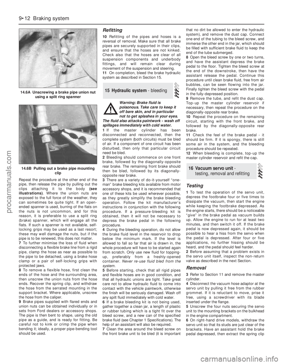
Repeat the procedure at the other end of the
pipe, then release the pipe by pulling out the
clips attaching it to the body (see
illustrations). Where the union nuts are
exposed to the full force of the weather, they
can sometimes be quite tight. If an open-
ended spanner is used, burring of the flats on
the nuts is not uncommon, and for this
reason, it is preferable to use a split ring
(brake) spanner, which will engage all the
flats. If such a spanner is not available, self-
locking grips may be used as a last resort;
these may well damage the nuts, but if the
pipe is to be renewed, this does not matter.
7To further minimise the loss of fluid when
disconnecting a flexible brake line from a rigid
pipe, clamp the hose as near as possible to
the pipe to be detached, using a brake hose
clamp or a pair of self-locking grips with
protected jaws.
8To remove a flexible hose, first clean the
ends of the hose and the surrounding area,
then unscrew the union nuts from the hose
ends. Recover the spring clip, and withdraw
the hose from the serrated mounting in the
support bracket. Where applicable, unscrew
the hose from the caliper.
9Brake pipes supplied with flared ends and
union nuts can be obtained individually or in
sets from Ford dealers or accessory shops.
The pipe is then bent to shape, using the old
pipe as a guide, and is ready for fitting. Be
careful not to kink or crimp the pipe when
bending it; ideally, a proper pipe-bending tool
should be used.
Refitting
10Refitting of the pipes and hoses is a
reversal of removal. Make sure that all brake
pipes are securely supported in their clips,
and ensure that the hoses are not kinked.
Check also that the hoses are clear of all
suspension components and underbody
fittings, and will remain clear during
movement of the suspension and steering.
11On completion, bleed the brake hydraulic
system as described in Section 15.
Warning: Brake fluid is
poisonous. Take care to keep it
off bare skin, and in particular
not to get splashes in your eyes.
The fluid also attacks paintwork - wash off
spillages immediately with cold water.
1If the master cylinder has been
disconnected and reconnected, then the
complete system (both circuits) must be bled
of air. If a component of one circuit has been
disturbed, then only that particular circuit
need be bled.
2Bleeding should commence on one front
brake, followed by the diagonally-opposite
rear brake. The remaining front brake should
then be bled, followed by its diagonally-
opposite rear brake.
3There are a variety of do-it-yourself “one-
man” brake bleeding kits available from motor
accessory shops, and it is recommended that
one of these kits be used wherever possible,
as they greatly simplify the brake bleeding
operation. Follow the kit manufacturer’s
instructions in conjunction with the following
procedure. If a pressure-bleeding kit is
obtained, then it will not be necessary to
depress the brake pedal in the following
procedure.
4During the bleeding operation, do not allow
the brake fluid level in the reservoir to drop
below the minimum mark. If the level is
allowed to fall so far that air is drawn in, the
whole procedure will have to be started again
from scratch. Only use new fluid for topping-
up, preferably from a freshly-opened
container. Never re-use fluid bled from the
system.
5Before starting, check that all rigid pipes
and flexible hoses are in good condition, and
that all hydraulic unions are tight. Take great
care not to allow hydraulic fluid to come into
contact with the vehicle paintwork, otherwise
the finish will be seriously damaged. Wash off
any spilt fluid immediately with cold water.
6If a brake bleeding kit is not being used,
gather together a clean jar, a length of plastic
or rubber tubing which is a tight fit over the
bleed screw, and a new can of the specified
brake fluid (see Chapter 1 Specifications). The
help of an assistant will also be required.
7Clean the area around the bleed screw on
the front brake unit to be bled (it is importantthat no dirt be allowed to enter the hydraulic
system), and remove the dust cap. Connect
one end of the tubing to the bleed screw, and
immerse the other end in the jar, which should
be filled with sufficient brake fluid to keep the
end of the tube submerged.
8Open the bleed screw by one or two turns,
and have the assistant depress the brake
pedal to the floor. Tighten the bleed screw at
the end of the downstroke, then have the
assistant release the pedal. Continue this
procedure until clean brake fluid, free from air
bubbles, can be seen flowing into the jar.
Finally tighten the bleed screw with the pedal
in the fully-depressed position.
9Remove the tube, and refit the dust cap.
Top-up the master cylinder reservoir if
necessary, then repeat the procedure on the
diagonally-opposite rear brake.
10Repeat the procedure on the remaining
circuit, starting with the front brake, and
followed by the diagonally-opposite rear
brake.
11Check the feel of the brake pedal - it
should be firm. If it is spongy, there is still
some air in the system, and the bleeding
procedure should be repeated.
12When bleeding is complete, top-up the
master cylinder reservoir and refit the cap.
Testing
1To test the operation of the servo unit,
depress the footbrake four or five times to
dissipate the vacuum, then start the engine
while keeping the footbrake depressed. As
the engine starts, there should be a noticeable
“give” in the brake pedal as vacuum builds
up. Allow the engine to run for at least two
minutes, and then switch it off. If the brake
pedal is now depressed again, it should be
possible to hear a hiss from the servo when
the pedal is depressed. After four or five
applications, no further hissing should be
heard, and the pedal should feel harder.
2Before assuming that a problem exists in
the servo unit itself, inspect the non-return
valve as described in the next Section.
Removal
3Refer to Section 11 and remove the master
cylinder.
4Disconnect the vacuum hose adaptor at the
servo unit by pulling it free from the rubber
grommet. If it is reluctant to move, prise it
free, using a screwdriver with its blade
inserted under the flange.
5Unscrew the four nuts securing the servo
unit to the mounting brackets on the bulkhead
in the engine compartment.
6On right-hand drive models, withdraw the
servo unit so that its studs are just clear of the
brackets. Have an assistant hold the brake
pedal depressed, then extract the spring clip
16 Vacuum servo unit -
testing, removal and refitting
15 Hydraulic system - bleeding
9•12 Braking system
14.6A Unscrewing a brake pipe union nut
using a split ring spanner
14.6B Pulling out a brake pipe mounting
clip
procarmanuals.com
Page 131 of 279
and remove the clevis pin securing the servo
unit pushrod to the pedal cross-link arm.
7On left-hand drive models, unscrew the nut
securing the pedal trunnion to the servo unit
pushrod inside the passenger compartment.
The nut is located near the top of the pedal,
and is accessible through an access hole. For
improved access, remove the lower facia
panel first.
8Withdraw the servo unit from the bulkhead,
and remove it from the engine compartment.
On left-hand drive models, take care not to
damage the bulkhead rubber grommet as the
pushrod passes through it.
9Note that the servo unit cannot be
dismantled for repair or overhaul and, if faulty,
must be renewed.
Refitting
10Refitting is a reversal of the removal
procedure. Refer to Section 11 for details of
refitting the master cylinder.
Removal
1Depress the brake pedal four or five times,
to dissipate any remaining vacuum from the
servo unit.
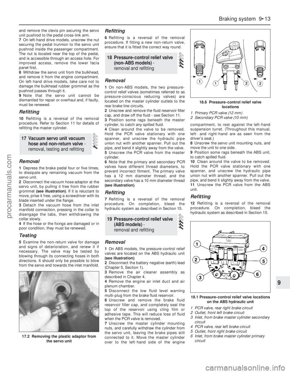
2Disconnect the vacuum hose adaptor at the
servo unit, by pulling it free from the rubber
grommet (see illustration). If it is reluctant to
move, prise it free, using a screwdriver with its
blade inserted under the flange.
3Detach the vacuum hose from the inlet
manifold connection, pressing in the collar to
disengage the tabs, then withdrawing the
collar slowly.
4If the hose or the fixings are damaged or in
poor condition, they must be renewed.
Testing
5Examine the non-return valve for damage
and signs of deterioration, and renew it if
necessary. The valve may be tested by
blowing through its connecting hoses in both
directions. It should only be possible to blow
from the servo end towards the inlet manifold.
Refitting
6Refitting is a reversal of the removal
procedure. If fitting a new non-return valve,
ensure that it is fitted the correct way round.
Removal
1On non-ABS models, the two pressure-
control relief valves (sometimes referred to as
pressure-conscious reducing valves) are
located on the master cylinder outlets to the
rear brake line circuits.
2Unscrew and remove the fluid reservoir filler
cap, and draw off the fluid - see Section 11.
3Position some rags beneath the master
cylinder, to catch any spilled fluid.
4Clean around the valve to be removed.
Hold the PCR valve stationary with one
spanner, and unscrew the hydraulic pipe
union nut with another spanner. Pull out the
pipe, and bend it slightly away from the valve.
5Unscrew the PCR valve from the master
cylinder.
6Note that the primary and secondary PCR
valves have different thread diameters, to
prevent incorrect fitment. The primary valve
has a 12 mm diameter thread, and the
secondary valve has a 10 mm diameter thread
(see illustration).
Refitting
7Refitting is a reversal of the removal
procedure. On completion, bleed the
hydraulic system as described in Section 15.
Removal
1On ABS models, the pressure-control relief
valves are located on the ABS hydraulic unit
(see illustration).
2Disconnect the battery negative (earth) lead
(Chapter 5, Section 1).
3Remove the air cleaner assembly as
described in Chapter 4.
4Remove the engine air inlet duct and air
plenum chamber.
5Disconnect the low fluid level warning
multi-plug from the brake fluid reservoir.
6Unscrew and remove the brake fluid
reservoir filler cap, and completely seal the
top of the reservoir using cling film or
adhesive tape. This will reduce loss of fluid
when the PCR valve is removed.
7Unscrew the master cylinder mounting
nuts, and carefully withdraw the cylinder from
the servo unit, leaving the brake pipes still
connected to it. Move the master cylinder
over to the left-hand side of the enginecompartment, to rest against the left-hand
suspension turret. (Throughout this manual,
left- and right-hand are as seen from the
driver’s seat.)
8Unscrew the servo unit mounting nuts, and
move the unit to one side.
9Position some rags beneath the ABS unit,
to catch spilled fluid.
10Clean around the valve to be removed.
Hold the PCR valve stationary with one
spanner, and unscrew the hydraulic pipe
union nut with another spanner. Pull out the
pipe, and bend it slightly away from the valve.
11Unscrew the PCR valve from the ABS
unit.
Refitting
12Refitting is a reversal of the removal
procedure. On completion, bleed the
hydraulic system as described in Section 15.
19 Pressure-control relief valve
(ABS models) -
removal and refitting
18 Pressure-control relief valve
(non-ABS models) -
removal and refitting
17 Vacuum servo unit vacuum
hose and non-return valve -
removal, testing and refitting
Braking system 9•13
9
17.2 Removing the plastic adaptor from
the servo unit
18.6 Pressure-control relief valve
locations
1 Primary PCR valve (12 mm)
2 Secondary PCR valve (10 mm)
19.1 Pressure-control relief valve locations
on the ABS hydraulic unit
1 PCR valve, rear right brake circuit
2 Outlet, front left brake circuit
3 Inlet, from brake master cylinder secondary
circuit
4 PCR valve, rear left brake circuit
5 Outlet, front right brake circuit
6 Inlet, from brake master cylinder primary
circuit
procarmanuals.com
Page 143 of 279
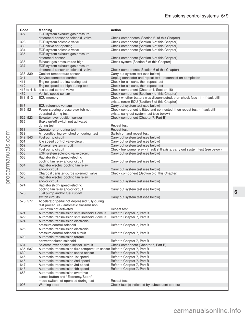
Code Meaning Action327 EGR system exhaust gas pressure
differential sensor or solenoid valve Check components (Section 6 of this Chapter)
328 EGR system solenoid valve Check component (Section 6 of this Chapter)
332 EGR valve not opening Check component (Section 6 of this Chapter)
334 EGR system solenoid valve Check component (Section 6 of this Chapter)335 EGR system exhaust gas pressure
differential sensor Check component (Section 6 of this Chapter)
336 Exhaust gas pressure too high Check system (Section 6 of this Chapter)337 EGR system exhaust gas pressure
differential sensor or solenoid valve Check components (Section 6 of this Chapter)
338, 339 Coolant temperature sensor Carry out system test (see below)
341 Service connector earthed Unplug connector and repeat test - reconnect on completion
411 Engine speed too low during test Check for air leaks, then repeat test
412 Engine speed too high during test Check for air leaks, then repeat test
413 to 416 Idle speed control valve Check component (Chapter 4, Section 16)
452 Vehicle speed sensor Check component (Section 4 of this Chapter)
511, 512 ECU memory Check whether battery was disconnected, then check fuse 11 - if fault still
exists, renew ECU (Section 6 of this Chapter)
513 ECU reference voltage Carry out system test (see below)
519, 521 Power steering pressure switch not Check component is fitted and connected, then repeat test - if fault still
operated during test exists, carry out system test (see below)
522, 523 Selector lever position sensor Check component (Chapter 7, Part B)
536 Brake on/off switch not activated
during test Repeat test
538 Operator error during test Repeat test
539 Air conditioning switched on during test Switch off and repeat test
542, 543 Fuel pump circuit Carry out system test (see below)
551 Idle speed control valve circuit Carry out system test (see below)
552 Pulse-air system circuit Carry out system test (see below)
556 Fuel pump circuit Check fuel pump relay - if fault still exists, carry out system test (see below)
558 EGR system solenoid valve circuit Carry out system test (see below)
563 Radiator (high-speed) electric
cooling fan relay and/or circuit Carry out system test (see below)564 Radiator electric cooling fan relay
and/or circuit Carry out system test (see below)
565 Charcoal canister-purge solenoid valve Check component (Section 5 of this Chapter)573 Radiator electric cooling fan relay
and/or circuit Carry out system test (see below)
574 Radiator (high-speed) electric
cooling fan relay and/or circuit Carry out system test (see below)575 Fuel pump and/or fuel cut-off
switch circuits Carry out system test (see below)
576, 577 Accelerator pedal not depressed fully during
test procedure - automatic transmission
kickdown not activated Repeat test
621 Automatic transmission shift solenoid 1 circuit Refer to Chapter 7, Part B
622 Automatic transmission shift solenoid 2 circuit Refer to Chapter 7, Part B
624 Automatic transmission electronic
pressure control solenoid Refer to Chapter 7, Part B
625 Automatic transmission electronic
pressure control solenoid circuit Refer to Chapter 7, Part B
629 Automatic transmission torque
converter clutch solenoid Refer to Chapter 7, Part B
634 Selector lever position sensor circuit Check component (Chapter 7, Part B)
635, 637 Automatic transmission fluid temperature sensor Refer to Chapter 7, Part B
639 Automatic transmission speed sensor Refer to Chapter 7, Part B
645 Automatic transmission 1st speed Refer to Chapter 7, Part B
646 Automatic transmission 2nd speed Refer to Chapter 7, Part B
647 Automatic transmission 3rd speed Refer to Chapter 7, Part B
648 Automatic transmission 4th speed Refer to Chapter 7, Part B
653 Automatic transmission overdrive
cancel button and “Economy/Sport”
mode switch not operated during test Repeat test
998 Warning code Check fault(s) indicated by subsequent code(s)
Emissions control systems 6•9
6
procarmanuals.com
Page 158 of 279
10•4 Suspension and steering systems
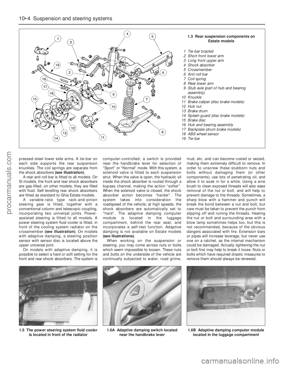
pressed-steel lower side arms. A tie-bar on
each side supports the rear suspension
knuckles. The coil springs are separate from
the shock absorbers (see illustration).
A rear anti-roll bar is fitted to all models. On
SI models, the front and rear shock absorbers
are gas-filled; on other models, they are filled
with fluid. Self-levelling rear shock absorbers
are fitted as standard to Ghia Estate models.
A variable-ratio type rack-and-pinion
steering gear is fitted, together with a
conventional column and telescopic coupling,
incorporating two universal joints. Power-
assisted steering is fitted to all models. A
power steering system fluid cooler is fitted, in
front of the cooling system radiator on the
crossmember (see illustration). On models
with adaptive damping, a steering position
sensor with sensor disc is located above the
upper universal joint.
On models with adaptive damping, it is
possible to select a hard or soft setting for the
front and rear shock absorbers. The system iscomputer-controlled; a switch is provided
near the handbrake lever for selection of
“Sport” or “Normal” mode. With this system, a
solenoid valve is fitted to each suspension
strut. When the valve is open, the hydraulic oil
inside the shock absorber is routed through a
bypass channel, making the action “softer”.
When the solenoid valve is closed, the shock
absorber action becomes “harder”. The
system takes into consideration the
roadspeed of the vehicle; at high speeds, the
shock absorbers are automatically set to
“hard”. The adaptive damping computer
module is located in the luggage
compartment, behind the rear seat, and
incorporates a self-test function. Adaptive
damping is not available on Estate models
(see illustrations).
When working on the suspension or
steering, you may come across nuts or bolts
which seem impossible to loosen. These nuts
and bolts on the underside of the vehicle are
continually subjected to water, road grime,mud, etc, and can become rusted or seized,
making them extremely difficult to remove. In
order to unscrew these stubborn nuts and
bolts without damaging them (or other
components), use lots of penetrating oil, and
allow it to soak in for a while. Using a wire
brush to clean exposed threads will also ease
removal of the nut or bolt, and will help to
prevent damage to the threads. Sometimes, a
sharp blow with a hammer and punch will
break the bond between a nut and bolt, but
care must be taken to prevent the punch from
slipping off and ruining the threads. Heating
the nut or bolt and surrounding area with a
blow lamp sometimes helps too, but this is
not recommended, because of the obvious
dangers associated with fire. Extension bars
or pipes will increase leverage, but never use
one on a ratchet, as the internal mechanism
could be damaged. Actually tighteningthe nut
or bolt first may help to break it loose. Nuts or
bolts which have required drastic measures to
remove them should always be renewed.
1.5 The power steering system fluid cooler
is located in front of the radiator
1.6A Adaptive damping switch located
near the handbrake lever1.6B Adaptive damping computer module
located in the luggage compartment
1.3 Rear suspension components on
Estate models
1 Tie-bar bracket
2 Short front lower arm
3 Long front upper arm
4 Shock absorber
5 Crossmember
6 Anti-roll bar
7 Coil spring
8 Rear lower arm
9 Stub axle (part of hub and bearing
assembly)
10 Knuckle
11 Brake caliper (disc brake models)
12 Hub nut
13 Brake drum
14 Splash guard (disc brake models)
15 Brake disc
16 Hub and bearing assembly
17 Backplate (drum brake models)
18 ABS wheel sensor
19 Tie-bar
procarmanuals.com