1993 DODGE TRUCK brake sensor
[x] Cancel search: brake sensorPage 602 of 1502
•
WIRING
DIAGRAMS
8W - 127
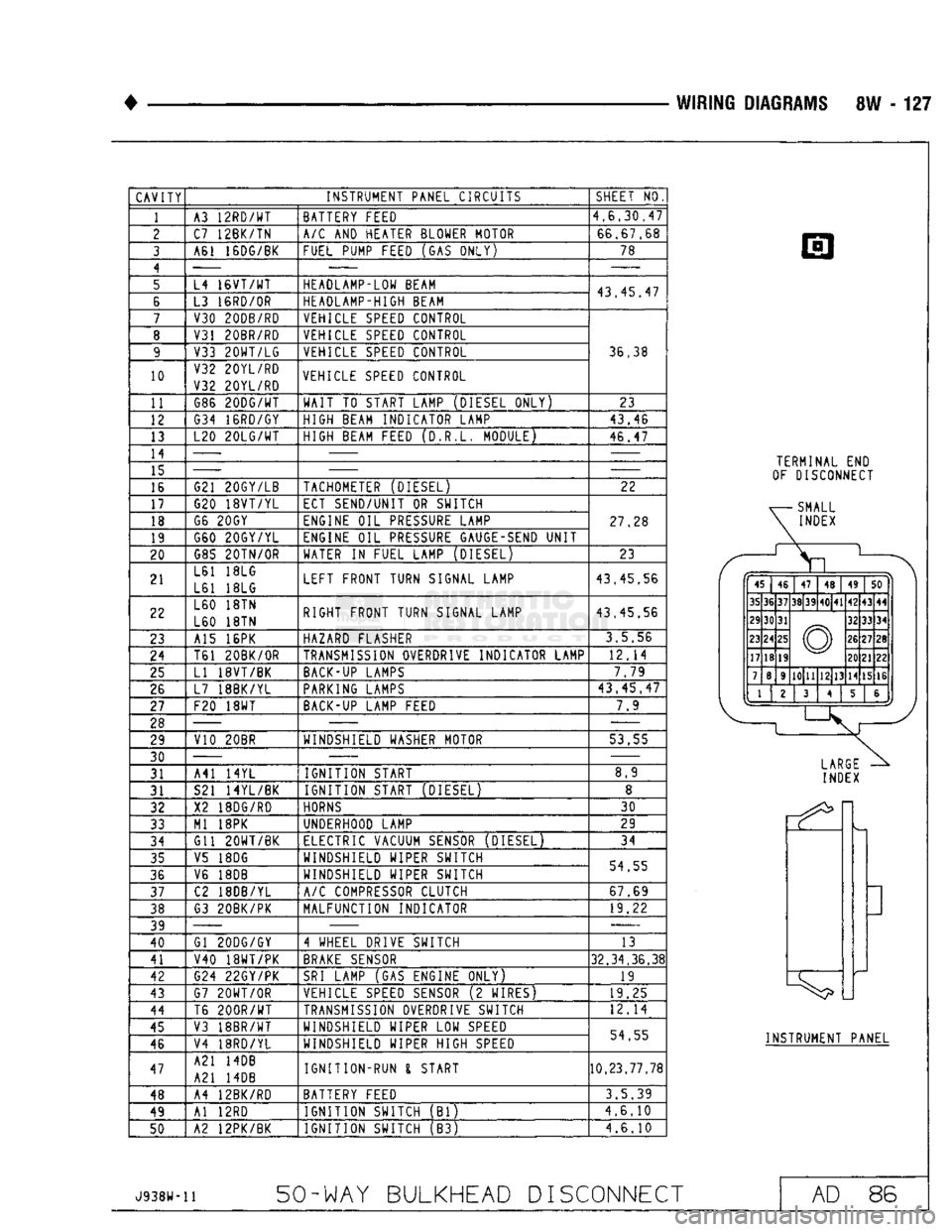
CAVITY
INSTRUMENT PANEL CIRCUITS
1
10
11
12
13
14
15
16
17
18
19
20
21
22
23
24
25
26
27
28 29
30 31
31
32
33
34
35
36
37
38
39
40
41
42
43
44
45
46
47
48
49
50
A3
12RD/WT
C7 12BK/TN
A61 16DG/BK
L4
16VT/WT
L3
16RD/0R
V30 20DB/RD
V31 20BR/RD
V33
20WT/LG
V32 20YL/RD
V32 20YL/RD G86
20DG/WT
G34 16RD/GY
L20
20LG/WT
G21 20GY/LB
G20
18VT/YL
G6
20GY
G60 20GY/YL G85
20TN/0R
L61
18LG
L61
18LG
L60
18TN
L60
18TN
A15
16PK
T61 20BK/OR
LI
18VT/BK
L7 18BK/YL
F20
18WT
V10 20BR
A41
14YL
S21 14YL/BK
X2
18DG/R0
Ml
18PK
Gil
20WT/BK
V5
18DG
V6
18DB
C2 18DB/YL
G3 20BK/PK
Gl 20DG/GY
V40
18WT/PK
G24 22GY/PK
G7
20WT/0R
T6
200R/WT
V3 18BR/WT
V4 18RD/YL
A21
14DB
A21
14DB
A4 12BK/RD
Al
12RD
A2 12PK/BK BATTERY FEED
A/C
AND
HEATER BLOWER MOTOR
FUEL PUMP FEED
(GAS
ONLY)
HEADLAMP-LOW BEAM
HEADLAMP-HIGH BEAM VEHICLE
SPEED
CONTROL
VEHICLE
SPEED
CONTROL VEHICLE
SPEED
CONTROL
VEHICLE
SPEED
CONTROL
WAIT
TO
START LAMP (DIESEL ONLY)
HIGH BEAM INDICATOR LAMP
HIGH BEAM FEED (D.R.L. MODULE)
TACHOMETER (DIESEL)
ECT SEND/UNIT
OR
SWITCH
ENGINE
OIL
PRESSURE
LAMP
ENGINE
OIL
PRESSURE
GAUGE-SEND
UNIT
WATER
IN
FUEL LAMP (DIESEL)
LEFT FRONT TURN SIGNAL LAMP
RIGHT FRONT TURN SIGNAL LAMP
HAZARD FLASHER
TRANSMISSION
OVERDRIVE INDICATOR LAMP
BACK-UP
LAMPS
PARKING
LAMPS
BACK-UP
LAMP FEED
WINDSHIELD WASHER MOTOR
IGNITION START
IGNITION START (DIESEL)
HORNS
UNDERHOOD LAMP
ELECTRIC VACUUM
SENSOR
(DIESEL) WINDSHIELD WIPER SWITCH
WINDSHIELD WIPER SWITCH
A/C
COMPRESSOR CLUTCH
MALFUNCTION INDICATOR
4 WHEEL DRIVE SWITCH
BRAKE
SENSOR
SRI
LAMP
(GAS
ENGINE ONLY)
VEHICLE
SPEED
SENSOR
(2
WIRES)
TRANSMISSION
OVERDRIVE SWITCH
WINDSHIELD WIPER
LOW
SPEED
WINDSHIELD WIPER HIGH
SPEED
IGNITION-RUN
I
START
BATTERY FEED IGNITION SWITCH
(Bl)
IGNITION SWITCH
(B3)
SHEET
NO
4,6.30,47
66,67,68 78
43,45,47
36,38
23
43,46
46,47
22
27,28
23
43.45,56
43,45.56
3,5,56
12,14 7.79
43,45,47
7.9
53.55 8,9
30
29
34
54,55 67,69 19,22
13
32,34,36,38
19
19,25
12,14
54.55
10,23.77,78
3.5.39
4,6.10
4.6.10
TERMINAL
END
OF DISCONNECT
ff
p
45 46
47
48 49
50
35 36 37
38 39
40 41
42
43 44
29 30 31
© 32
33 34
23 24
25
© 26
27 28
17 18
19 ©
20 21 22
7 8 9
10 11
12 13
14 15 16
1
^
1.
2
3
4 5 &
J *j
LARGE
INDEX
INSTRUMENT PANEL
J938W-11
50-WAY BULKHEAD
DISCONNECT
AD
86
Page 605 of 1502
8W - 130
WIRING
DIAGRAMS
•
1 2 3
A 4
5 6
7
8
/
9
10
11
/
12 13
14
15 16
/
17
18
19
20
21
u
22
23
24
25 26
u
27
28 29
30
31
u
32 33
34
u
35 36
37
38 39
u
40
41 42
u
VIEW FROM WIRE
END
HEADLAMP
I
DASH
WIRING
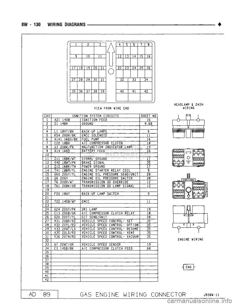
CAV
IGNITION
SYSTEM CIRCUITS
SHEET
NO
1 A21
14DB
IGNITION
FEED 16
2
Zl 14BK
GROUND
9.68
3
4
LI 18VT/BK BACK-UP LAMPS 9
5 K54 200R/BK
EMCC
SOLENOID
11
6 A141 16DG/BK
FUEL PUMP 16
7
C20
18BR
A/C
COMPRESSOR CLUTCH 18
8 G3 20BK/PK MALFUNCTION INDICATOR LAMP 19
9 A14
16RD
BATTERY FEED 16
10
11
Zll
16BK/WT
SIGNAL GROUND
17
12 V40 18WT/PK
BRAKE
SIGNAL 35
13 Z12 16BK/TN
POWER
GROUND
17
14
T41 18BR/YL ENGINE STARTER RELAY COIL 9
15 G60 20GY/YL ENGINE
OIL
PRESSURE
SEND/UNIT 28
16 G6 20GY
ENGINE
OIL
PRESSURE
SWITCH 28
17 T6
200R/WT
TRANSMISSION
OD
OVERRIDE 12
18 T61 20BK/0R
TRANSMISSION
OD
LAMP SIGNAL
12
19
20
F20
18WT
BACK-UP LAMP SWITCH 9
21
22 T22 14DB/WT
EMCC
11
23
24
G24 20GY/PK
SRI
LAMP
19
25 C13 20DB/0R
A/C
COMPRESSOR CLUTCH RELAY
18
26 G20
20VT/YL
ECT SEND/UNIT
28
27
V31 20BR/RD VEHICLE
SPEED
CONTROL-
SET
35
28 V32 20YL/RD VEHICLE
SPEED
CONTROL- OFF/ON
35
29 V33
20WT/LG
VEHICLE
SPEED
CONTROL- RESUME 35
30
V35 20LG/RD VEHICLE
SPEED
CONTROL- VENT
35
31 V36 20TN/RD VEHICLE
SPEED
CONTROL- VACUUM
35
32
33 G7
20WT/0R
VEHICLE
SPEED
SENSOR 19
34
C3 14DB/BK
A/C
COMPRESSOR CLUTCH FEED 68
35
36
37
38
39
40
41
42
&
GjCUQjQ
UXJUXj
O
"IT
mJKXTV
ENGINE WIRING
- ENG
AD
89
GAS
ENGINE WIRING CONNECTOR
J938W-11
Page 848 of 1502
•
FUEL
SYSTEM
14-29
MULTI-PORT
FUEL
INJECTION
(MPI)-COMPONENT DESCRIPTION/SYSTEM
OPERATION-EXCEPT DIESEL
INDEX
page
Air
Conditioning (A/C) Clutch
Relay-Pern
Output
. 35
Air
Conditioning (A/C)
Controls—PCM
Input
.... 31
Auto
Shut
Down
(ASD)
Relay-PCM
Output
. ... 36
Automatic
Shut
Down
(ASD)
Sense-PCM
Input
. 31
Battery
Voltage-PCM
Input
32
Brake
Switch-PCM
Input
32
Camshaft
Position
Sensor—PCM
Input
32
Charge
Air
Temperature
Sensor—PCM
Input
. . . 32
Crankshaft
Position
Sensor-PCM
Input
.......
32
Electric
Exhaust
Gas Recirculation Transducer
(EET)
Solenoid-PCM
Output
...
.......
36
Engine
Coolant Temperature
Sensor—PCM
Input
. 33
EVAP
Canister
Purge
Solenoid—PCM
Output
. . . 37
Fuel
Injectors-PCM Output
37
Fuel
Pressure
Regulator
41
Fuel
Rail
41
General
Information
.......................
29
Generator
Field-PCM
Output
36
Generator
Lamp-PCM
Output
36
Idle
Air
Control
(IAC)
Motor-PCM
Output
......
36
Ignition
Circuit
Sense—PCM
Input
33
GENERAL
INFORMATION
All
gas
powered engines
are
equipped with sequen
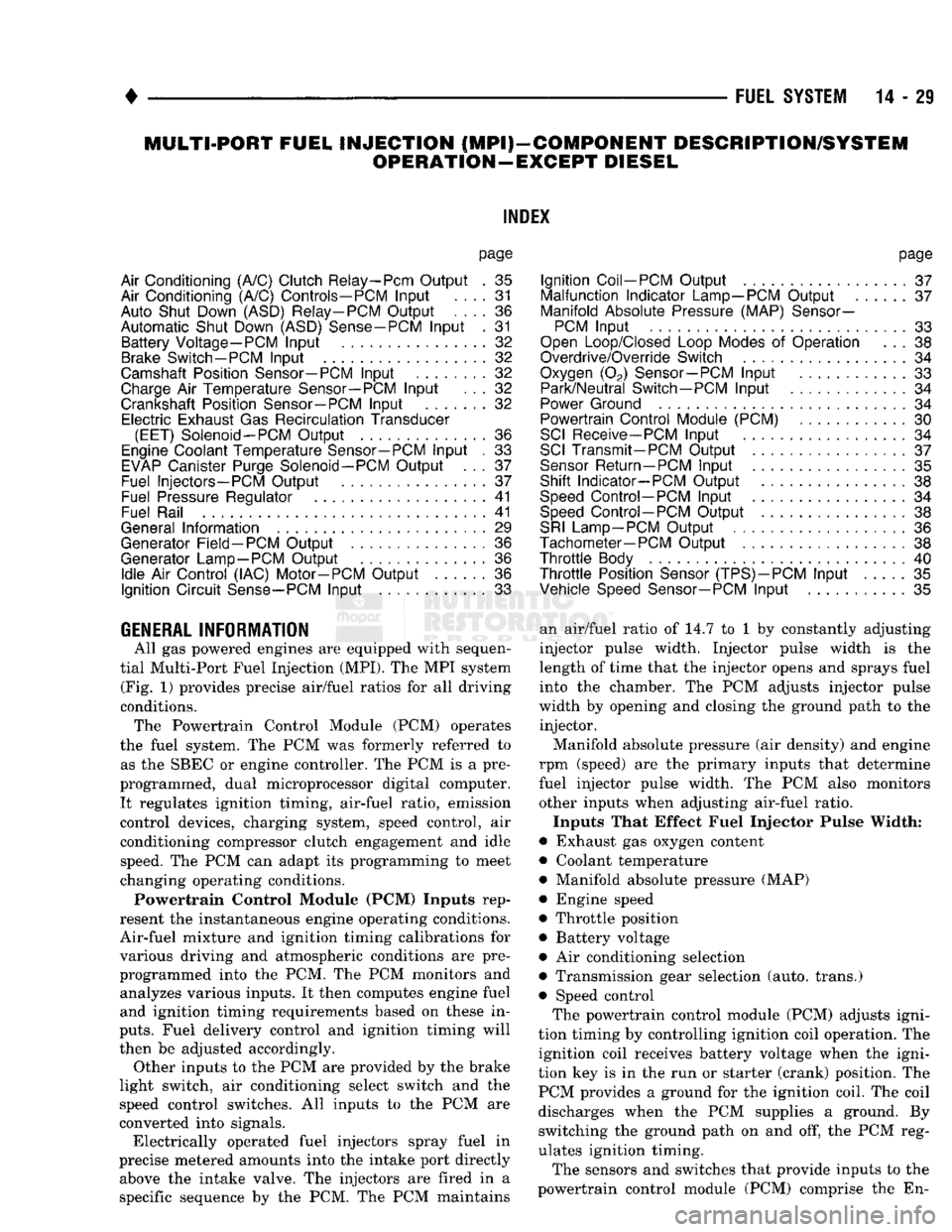
tial Multi-Port Fuel Injection (MPI).
The MPI
system (Fig.
1)
provides precise air/fuel ratios
for all
driving
conditions. The Powertrain Control Module
(PCM)
operates
the fuel system.
The PCM was
formerly referred
to
as
the
SBEC
or
engine controller.
The PCM is a
pre
programmed, dual microprocessor digital computer. It regulates ignition timing, air-fuel ratio, emission
control devices, charging system, speed control,
air
conditioning compressor clutch engagement
and
idle speed.
The PCM can
adapt
its
programming
to
meet
changing operating conditions.
Powertrain Control Module (PCM) Inputs rep
resent
the
instantaneous engine operating conditions.
Air-fuel mixture
and
ignition timing calibrations
for
various driving
and
atmospheric conditions
are
pre
programmed into
the PCM. The PCM
monitors
and
analyzes various inputs.
It
then computes engine fuel
and ignition timing requirements based
on
these
in
puts.
Fuel delivery control
and
ignition timing will
then
be
adjusted accordingly. Other inputs
to the
PCM
are
provided
by the
brake
light switch,
air
conditioning select switch
and the
speed control switches.
All
inputs
to the PCM are
converted into signals. Electrically operated fuel injectors spray fuel
in
precise metered amounts into
the
intake port directly above
the
intake valve.
The
injectors
are
fired
in a
specific sequence
by the PCM. The PCM
maintains
page
Ignition
Coil-PCM
Output
37
Malfunction Indicator
Lamp—PCM
Output
37
Manifold
Absolute
Pressure
(MAP)
Sensor-
PCM
Input
33
Open
Loop/Closed
Loop
Modes
of
Operation
. . . 38
Overdrive/Override
Switch
34
Oxygen
(02)
Sensor—PCM
Input
33
Park/Neutral
Switch—PCM
Input
34
Power
Ground
34
Powertrain Control Module
(PCM)
30
SCI
Receive-PCM
Input
. 34
SCI
Transmit-PCM
Output
37
Sensor
Return
—PCM
Input
35
Shift Indicator-PCM Output
38
Speed
Control-PCM
Input
34
Speed
Control-PCM
Output
38
SRI
Lamp-PCM
Output
36
Tachometer—PCM
Output
38
Throttle
Body
40
Throttle
Position
Sensor
(TPS)-PCM
Input
35
Vehicle
Speed
Sensor-PCM
Input
35
an air/fuel ratio
of 14.7 to 1 by
constantly adjusting
injector pulse width. Injector pulse width
is the
length
of
time that
the
injector opens
and
sprays fuel into
the
chamber.
The PCM
adjusts injector pulse
width
by
opening
and
closing
the
ground path
to the
injector.
Manifold absolute pressure
(air
density)
and
engine
rpm (speed)
are the
primary inputs that determine
fuel injector pulse width.
The PCM
also monitors
other inputs when adjusting air-fuel ratio.
Inputs That Effect Fuel Injector Pulse Width:
• Exhaust
gas
oxygen content
• Coolant temperature
• Manifold absolute pressure (MAP)
• Engine speed
• Throttle position
• Battery voltage •
Air
conditioning selection
• Transmission gear selection (auto, trans.)
• Speed control The powertrain control module (PCM) adjusts igni
tion timing
by
controlling ignition coil operation.
The
ignition coil receives battery voltage when
the
igni
tion
key is in the run or
starter (crank) position.
The
PCM provides
a
ground
for the
ignition coil.
The
coil
discharges when
the PCM
supplies
a
ground.
By
switching
the
ground path
on and off, the PCM
reg
ulates ignition timing.
The sensors
and
switches that provide inputs
to the
powertrain control module
(PCM)
comprise
the En-
Page 849 of 1502
14
- 30
FUEL
SYSTEM
INPUTS
OUTPUTS
POWERTRAIN
CONTROL
MODULE
DRB
II
SCAN
TOOL
SPEED
CONTROL
BRAKE
SWITCH
A/C
LOW
PRESSURE
CUTOFF
SWITCH VEHICLE
SPEED
SENSOR PARK/NEUTRAL
SWITCH TORQUE CONVERTER
CLUTCH SOLENOID
MALFUNCTION
INDICATOR
LAMP
m
HEATED
i
*OXYGEN SENSOR ENGINE
COOLANT
yy
BATTERY
TEMPERATURE
SENSOR
MAP SENSOR
i—r
CHARGE
AIR
TEMPERATURE
SENSOR
AIR CHARGE
TEMPERATURE
SENSOR
DISTRIBUTOR
WITH
CAMSHAFT
r
POSITION
SENSOR
(|
TACHOMETER
A/C
CLUTCH RELAY
AUTO
SHUTDOWN
RELAY OVERDRIVE
SOLENOID
IDLE AIR
CONTROL MOTOR
SPEED
CONTROL
SHIFT
INDICATOR
LAMP
EMISSION
CONTROL SOLENOIDS
IGNITION
COIL
OVERDRIVE
OVERRIDE SWITCH
ASD
SENSE
FUEL
INJECTORS
PARK
THROTTLE
SOLENOID
GENERATOR CRANKSHAFT
POSITION FUEL
PUMP
RELAY
J9314-117
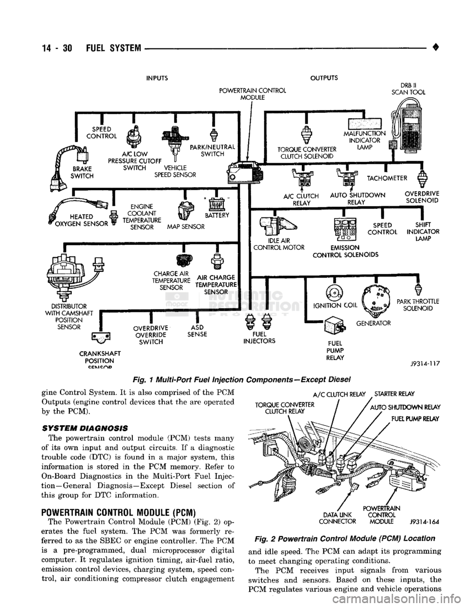
Fig.
1 Multi-Port
Fuel
Injection
Components—Except
Diesel
gine Control System. It is also comprised of the PCM Outputs (engine control devices that the are operated
by the PCM).
SYSTEM DIAGNOSIS
The powertrain control module (PCM) tests many
of its own input and output circuits. If a diagnostic
trouble code (DTC) is found in a major system, this information is stored in the PCM memory. Refer to
On-Board Diagnostics in the Multi-Port Fuel Injec
tion—General Diagnosis—Except Diesel section of
this group for DTC information.
POWERTRAIN
CONTROL MODULE (PCM)
The Powertrain Control Module (PCM) (Fig. 2) op
erates the fuel system. The PCM was formerly re
ferred to as the SBEC or engine controller. The PCM is a pre-programmed, dual microprocessor digital computer. It regulates ignition timing, air-fuel ratio, emission control devices, charging system, speed control, air conditioning compressor clutch engagement
A/C
CLUTCH RELAY STARTER RELAY
TORQUE CONVERTER CLUTCH RELAY
AUTO
SHUTDOWN RELAY
FUEL PUMP RELAY
DATA UNK
CONNECTOR
POWERTRAIN
CONTROL MODULE
J9314-164
Fig.
2 Powertrain Control
Module
(PCM) Location and idle speed. The PCM can adapt its programming
to meet changing operating conditions.
The PCM receives input signals from various
switches and sensors. Based on these inputs, the
PCM regulates various engine and vehicle operations
Page 850 of 1502
•
FUEL SYSTEM
14-31 through different system components. These compo
nents are referred to as Powertrain Control Module
(PCM) Outputs. The sensors and switches that pro
vide inputs to the PCM are considered Powertrain Control Module (PCM) Inputs.
The PCM adjusts ignition timing based upon in
puts it receives from sensors that react to: engine rpm, manifold absolute pressure, engine coolant tem
perature, throttle position, transmission gear selec
tion (automatic transmission), vehicle speed and the
brake switch.
The PCM adjusts idle speed based on inputs it re
ceives from sensors that react to: throttle position,
vehicle speed, transmission gear selection, engine coolant temperature and from inputs it receives from
the air conditioning clutch switch and brake switch.
Based on inputs that it receives, the PCM adjusts
ignition coil dwell. The PCM also adjusts the gener
ator charge rate through control of the generator
field and provides speed control operation.
Powertrain Control Module (PCM) Inputs:
• Generator output • A/C request (if equipped with factory A/C)
• A/C select (if equipped with factory A/C)
• Auto shut down (ASD) sense
• Charge air temperature sensor
• Battery voltage
• Brake switch
• Engine coolant temperature sensor
• Crankshaft position sensor • Ignition circuit sense (ignition switch in run posi
tion)
• Manifold absolute pressure (MAP) sensor
• Overdrive/override switch
• Oxygen sensor(s)
• Park/neutral switch (auto, trans, only)
• SCI receive (DRB II connection) • Speed control resume switch
• Speed control set switch • Speed control on/off switch
• Camshaft position sensor signal
• Throttle position sensor
• Vehicle speed sensor
• Sensor return
• Power ground
• Signal ground Powertrain Control Module (PCM) Outputs:
• A/C clutch relay
• Idle air control (IAC) motor
• Auto shut down (ASD) relay
• Generator field
• Malfunction indicator lamp
• Service reminder indicator lamp
• EGR valve control solenoid • Fuel injectors
• Fuel pump relay
• Ignition coil • EVAP canister purge solenoid
• SCI transmit (DRB II connection)
• Shift indicator lamp (manual transmission only)
• Speed control vacuum solenoid
• Speed control vent solenoid
• Tachometer (on instrument panel, if equipped) The powertrain control module (PCM) contains a
voltage convertor. This converts battery voltage to a
regulated 8.0 volts. It is used to power the crankshaft
position sensor and camshaft position sensor. The
PCM also provides a five (5) volt supply for the man ifold absolute pressure (MAP) sensor and throttle po
sition sensor (TPS).
AIR
CONDITIONING
(A/C)
CONTROLS-PCM
INPUT
The A/C control system information applies to fac
tory installed air conditioning units. A/C SELECT SIGNAL: When the A/C switch is
in the ON position and the A/C low pressure switch
is closed, an input signal is sent to the powertrain
control module (PCM). The signal informs the PCM
that the A/C has been selected. The PCM adjusts idle speed to a pre-programmed rpm through the idle air
control (IAC) motor to compensate for increased en
gine load. A/C REQUEST SIGNAL: Once A/C has been se
lected, the powertrain control module (PCM) receives
the A/C request signal from the evaporator switch.
The input indicates that the evaporator temperature is in the proper range for A/C application. The PCM
uses this input to cycle the A/C compressor clutch (through the A/C relay). It will also determine the
correct engine idle speed through the idle air control (IAC) motor position. If the A/C low pressure switch opens (indicating a
low refrigerant level), the PCM will not receive an
A/C select signal. The PCM will then remove the ground from the A/C relay. This will deactivate the
A/C compressor clutch. If the evaporator switch opens, (indicating that
evaporator is not in proper temperature range), the
PCM will not receive the A/C request signal. The
PCM will then remove the ground from the A/C re lay, deactivating the A/C compressor clutch.
AUTOMATIC SHUT DOWN
(ASD)
SENSE-PCM INPUT
A 12 volt signal at this input indicates to the PCM
that the ASD has been activated. The ASD relay is located in the engine compartment (Fig. 2). It is used
to connect the oxygen sensor(s) heater element, igni
tion coil, generator field winding and fuel injectors to 12 volt + power supply. This input is used only to sense that the ASD relay
is energized. If the powertrain control module (PCM)
does not see 12 volts at this input when the ASD
should be activated, it will set a diagnostic trouble
code (DTC).
Page 851 of 1502
14
- 32
FUEL SYSTEM
•
BATTERY VOLTAGE—PCM
INPUT
The battery voltage input provides power
to the
powertrain control module (PCM).
It
also informs
the
PCM what voltage level
is
supplied
to the
ignition
coil
and
fuel injectors. If battery voltage
is low, the PCM
will increase injec
tor pulse width (period
of
time that
the
injector
is
ener
gized).
This
is
done
to
compensate
for the
reduced flow
through injector caused
by the
lowered voltage.
BRAKE
SWITCH-PCM
INPUT
When
the
brake light switch
is
activated,
the
pow
ertrain control module
(PCM)
receives
an
input indi
cating that
the
brakes
are
being applied. After
receiving this input,
the PCM
maintains idle speed
to
a
scheduled
rpm
through control
of the
idle
air
control
(IAC)
motor.
The
brake switch input
is
also
used
to
operate
the
speed control system.
CAMSHAFT POSITION SENSOR—PCM
INPUT
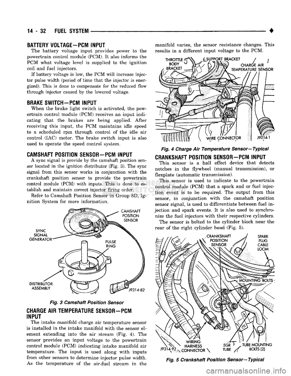
A sync signal
is
provide
by the
camshaft position sen
sor located
in the
ignition distributor
(Fig.
3).
The
sync
signal from this sensor works
in
conjunction with
the
crankshaft position sensor
to
provide
the
powertrain
control module
(PCM)
with inputs. This
is
done
to es
tablish
and
maintain correct injector firing order. Refer
to
Camshaft Position Sensor
in
Group
8D, Ig
nition System
for
more information.
Fig.
3
Camshaft Position
Sensor
CHARGE AIR TEMPERATURE SENSOR-PCM
INPUT
The intake manifold charge
air
temperature sensor
is installed
in the
intake manifold with
the
sensor
el
ement extending into
the air
stream
(Fig. 4). The
sensor provides
an
input voltage
to the
powertrain control module
(PCM)
indicating intake manifold
air
temperature.
The
input
is
used along with inputs from other sensors
to
determine injector pulse width. As
the
temperature
of the
air-fuel stream
in the
manifold varies,
the
sensor resistance changes. This
results
in a
different input voltage
to the PCM.
Fig.
4
Charge
Air
Temperature
Sensor—Typical
CRANKSHAFT POSITION SENSOR-PCM INPUT
This sensor
is a
hall effect device that detects
notches
in the
flywheel (manual transmission),
or
flexplate (automatic transmission). This sensor
is
used
to
indicate
to the
powertrain
control module
(PCM)
that
a
spark
and or
fuel injec
tion event
is to be
required.
The
output from this sensor,
in
conjunction with
the
camshaft position
sensor signal,
is
used
to
differentiate between fuel
in
jection
and
spark events.
It is
also used
to
synchro nize
the
fuel injectors with their respective cylinders. The sensor
is
bolted
to the
cylinder block near
the
rear
of the
right cylinder head
(Fig. 5).
Fig.
5
Crankshaft Position Sensor—Typical
Page 864 of 1502
•
FUEL
SYSTEM
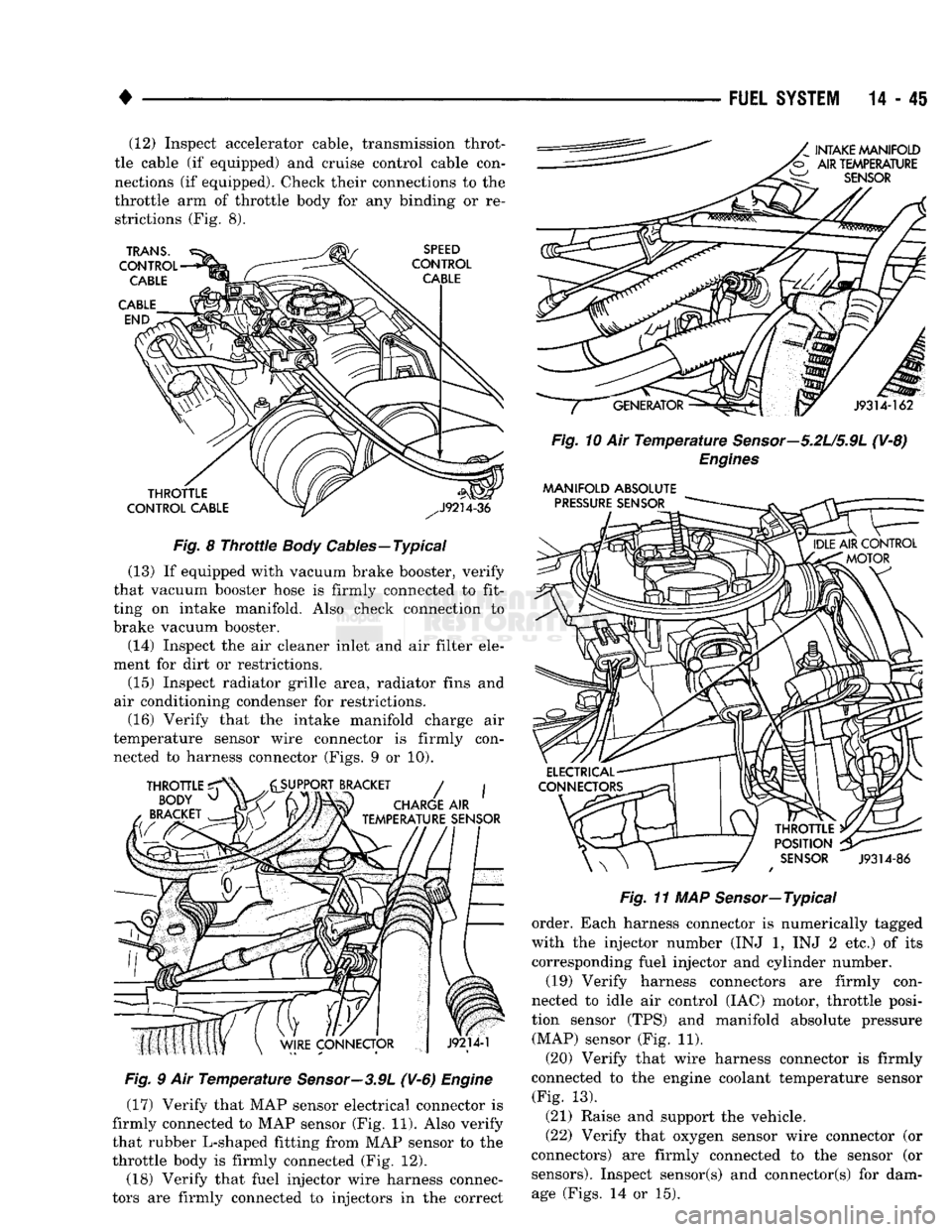
14-45 (12) Inspect accelerator cable, transmission throt
tle cable (if equipped) and cruise control cable con
nections (if equipped). Check their connections to the
throttle arm of throttle body for any binding or re strictions (Fig. 8).
Fig.
8
Throttle
Body
Cables—Typical
(13) If equipped with vacuum brake booster, verify
that vacuum booster hose is firmly connected to fit
ting on intake manifold. Also check connection to
brake vacuum booster.
(14) Inspect the air cleaner inlet and air filter ele
ment for dirt or restrictions.
(15) Inspect radiator grille area, radiator fins and
air conditioning condenser for restrictions. (16) Verify that the intake manifold charge air
temperature sensor wire connector is firmly con nected to harness connector (Figs. 9 or 10).
Fig.
9 Air
Temperature
Sensor—3.9L
(V-6)
Engine
(17) Verify that MAP sensor electrical connector is
firmly connected to MAP sensor (Fig. 11). Also verify
that rubber L-shaped fitting from MAP sensor to the
throttle body is firmly connected (Fig. 12).
(18) Verify that fuel injector wire harness connec
tors are firmly connected to injectors in the correct
Fig.
10 Air
Temperature
Sensor—5.2U5.9L
(V-8)
Engines
MANIFOLD
ABSOLUTE
Fig.
11 MAP Sensor—Typical
order. Each harness connector is numerically tagged
with the injector number (INJ 1, INJ 2 etc.) of its
corresponding fuel injector and cylinder number.
(19) Verify harness connectors are firmly con
nected to idle air control (IAC) motor, throttle posi
tion sensor (TPS) and manifold absolute pressure (MAP) sensor (Fig. 11).
(20) Verify that wire harness connector is firmly
connected to the engine coolant temperature sensor (Fig. 13).
(21) Raise and support the vehicle.
(22) Verify that oxygen sensor wire connector (or
connectors) are firmly connected to the sensor (or sensors). Inspect sensor(s) and connector(s) for damage (Figs. 14 or 15).
Page 867 of 1502
CAV
WIRE
COLOR DESCRIPTION
CAV
WIRE
COLOR DESCRIPTION
1 DG/RD*
MAP SENSOR 37
BK/OR OVERDRIVE LAMP
2 TN/BK*
ENGINE COOLANT TEMPERATURE SENSOR 38 PK/BK INJECTOR DRIVE
#5
3 RD/WT DIRECT BATTERY 39 GY/RD IAC MOTOR
#4
4
BK/LB*
SENSOR RETURN 40 BR/WT
IAC MOTOR
#2
5 BK/WT SIGNAL GROUND 41
BK/DG* OXYGEN SENSOR SIGNAL
6 VT/WT
5-VOLT
OUTPUT
(MAP AND TPS)
42
7 OR
8-VOLT
OUTPUT (DISTRIBUTOR PICK-UP) 43
GY/LB*
TACHOMETER SIGNAL OUTPUT (VEHICLES W/TACHOMETER)
8 44 GY CAMSHAFT POSITION SENSE
9 DB
J2-IGNITION FEED 45
LG SCI RECIEVE
10 R/WT OVERDRIVE OVERRIDE
46 CCD
(-)
11 BK/TN POWER GROUND 47 WT/OR* SPEED SENSOR SIGNAL
12 BK/TN POWER GROUND 48 BR/RD* SPEED CONTROL
SET
SWITCH
13 LB/BR
INJECTOR DRIVER
#4
49
YL/RD* SPEED CONTROL ON/OFF SWITCH
14 YL/WT
INJECTOR DRIVER
#3
50 WT/LG* SPEED CONTROL RESUME SWITCH
15 TN INJECTOR DRIVER
#2
51 DB/YL*
AUTO SHUTDOWN
(ASD)
RELAY
-
RETURN
16
WT/DB*
INJECTOR DRIVER
#1
52 PK/BK
EVAP CANISTER PURGE SOLENOID
17 DB/TN INJECTOR DRIVER
#7
(V-8
ONLY) 53 LG/RD* SPEED CONTROL VENT SOLENOID
18 DB/GY
INJECTOR DRIVER
#8
(V-8
ONLY) 54
OR/BK* SHIFT INDICATOR LIGHT (MANUAL TRANSMISSION ONLY)
19 BK/GY*
IGNITION COIL DRIVER 54
OR/BK* CONVERTOR CLUTCH SOLENOID (AUTO TRANSMISSION)
20 DG
GENERATOR FIELD CONTROL 55
OR/WT OVERDRIVE SOLENOID (AUTO TRANSMISSION ONLY)
21 BK/RD
CHARGE TEMPERATURE SENSOR 56
GY/PK SRI LAMP
(5.9L HDC
ENGINE)
22
OR/DB*
THROTTLE POSITION SENSOR
(TPS)
57
DG/OR ASD SENSE
23 TN/WT
OXYGEN SENSOR SIGNAL
(5.9L HDC
ENGINE) 58 LG/BK
INJECTOR DRIVER
#6
24 GY/BK IGNITION (CAMSHAFT POSITION SENSOR) 59
VT/BK IAC MOTOR
#1
25 PK
,
SCI
TRANSMIT 60
YL/BK* IAC MOTOR
#3
26 CCD
(-:-)
WIRE COLOR CODES LB
LIGHT BLUE
VT VIOLET
27 BR
A/C SWITCH SENSE BK BLACK
LG LIGHT GREEN
WT
WHITE
28 VT A/C SELECT BR BROWN
OR ORANGE
YL YELLOW
29 WT/PK* BRAKE SWITCH
-
DB DARK BLUE PK
PINK *
WITH TRACER
30 BY/YL*
PARK/NEUTRAL SWITCH DG DARK GREEN
RD
RED
31 GY
GRAY TN TAN
32 BK/PK*
MALFUNCTION INDICATOR LAMP
33 TN/RD*
SPEED CONTROL VACUUM SOLENOID CONNECTOR
34 DB/OR* A/C CLUTCH RELAY TERMINAL
|(pcKX>coooop0ffoj'
oooooooooojj
35 GY/YL*
EGR SOLENOID SHOWN W'41
30
50«M#5l31
604
%\
oooooooooo ••ooooooooooj
36 J9314-171
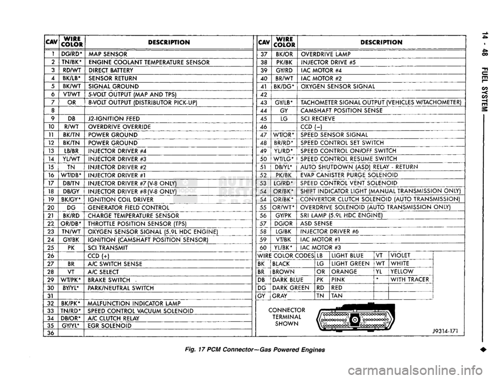
Fig.
17 PCM
Connector—Gas
Powered
Engines