Page 2343 of 2438

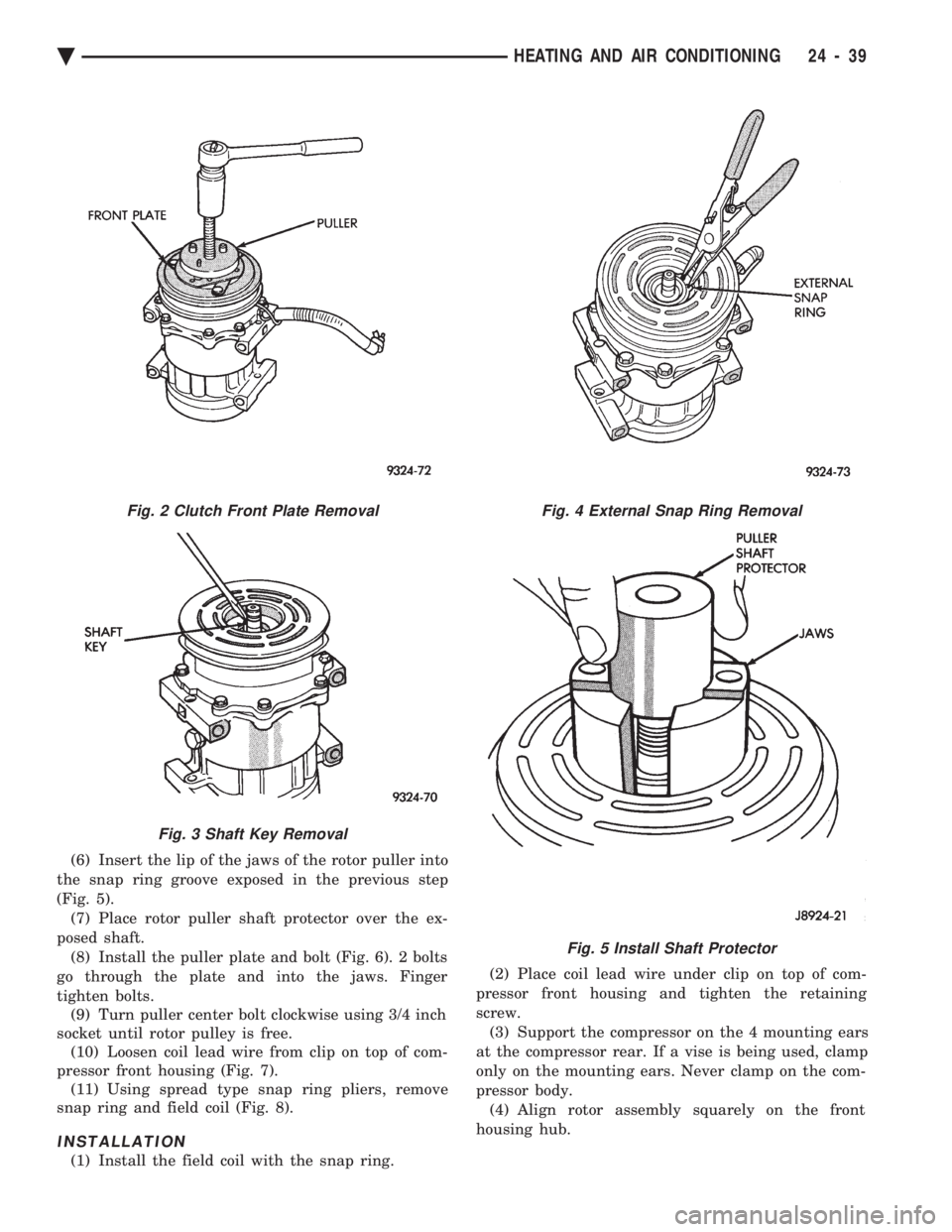
(6) Insert the lip of the jaws of the rotor puller into
the snap ring groove exposed in the previous step
(Fig. 5). (7) Place rotor puller shaft protector over the ex-
posed shaft. (8) Install the puller plate and bolt (Fig. 6). 2 bolts
go through the plate and into the jaws. Finger
tighten bolts. (9) Turn puller center bolt clockwise using 3/4 inch
socket until rotor pulley is free. (10) Loosen coil lead wire from clip on top of com-
pressor front housing (Fig. 7). (11) Using spread type snap ring pliers, remove
snap ring and field coil (Fig. 8).
INSTALLATION
(1) Install the field coil with the snap ring. (2) Place coil lead wire under clip on top of com-
pressor front housing and tighten the retaining
screw. (3) Support the compressor on the 4 mounting ears
at the compressor rear. If a vise is being used, clamp
only on the mounting ears. Never clamp on the com-
pressor body. (4) Align rotor assembly squarely on the front
housing hub.
Fig. 2 Clutch Front Plate Removal
Fig. 3 Shaft Key Removal
Fig. 4 External Snap Ring Removal
Fig. 5 Install Shaft Protector
Ä HEATING AND AIR CONDITIONING 24 - 39
Page 2344 of 2438

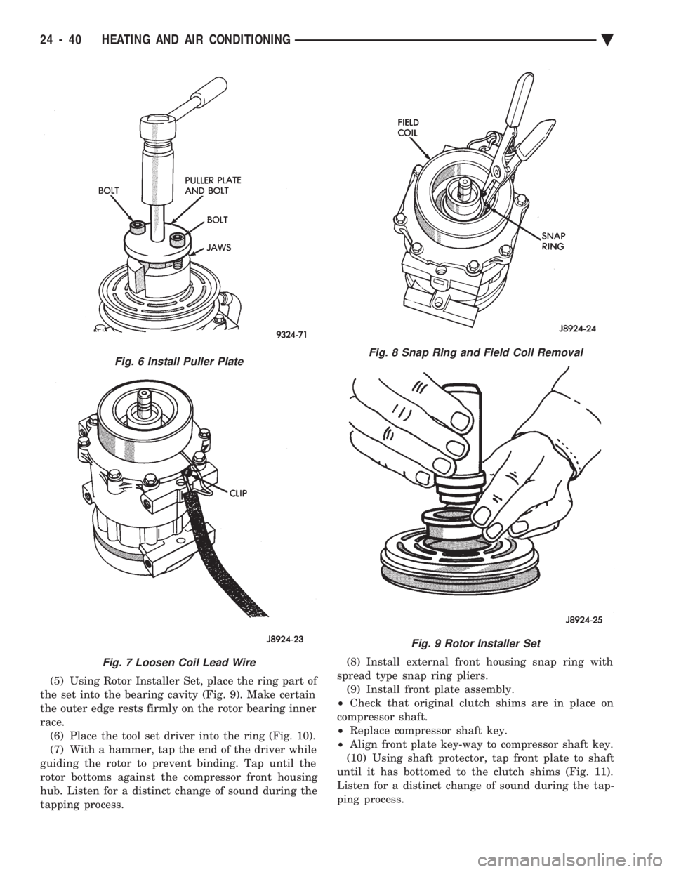
(5) Using Rotor Installer Set, place the ring part of
the set into the bearing cavity (Fig. 9). Make certain
the outer edge rests firmly on the rotor bearing inner
race. (6) Place the tool set driver into the ring (Fig. 10).
(7) With a hammer, tap the end of the driver while
guiding the rotor to prevent binding. Tap until the
rotor bottoms against the compressor front housing
hub. Listen for a distinct change of sound during the
tapping process. (8) Install external front housing snap ring with
spread type snap ring pliers. (9) Install front plate assembly.
² Check that original clutch shims are in place on
compressor shaft.
² Replace compressor shaft key.
² Align front plate key-way to compressor shaft key.
(10) Using shaft protector, tap front plate to shaft
until it has bottomed to the clutch shims (Fig. 11).
Listen for a distinct change of sound during the tap-
ping process.
Fig. 6 Install Puller Plate
Fig. 7 Loosen Coil Lead Wire
Fig. 8 Snap Ring and Field Coil Removal
Fig. 9 Rotor Installer Set
24 - 40 HEATING AND AIR CONDITIONING Ä
Page 2346 of 2438

Shaft seal replacement should be done on the
bench. Never use any old parts of the shaft seal
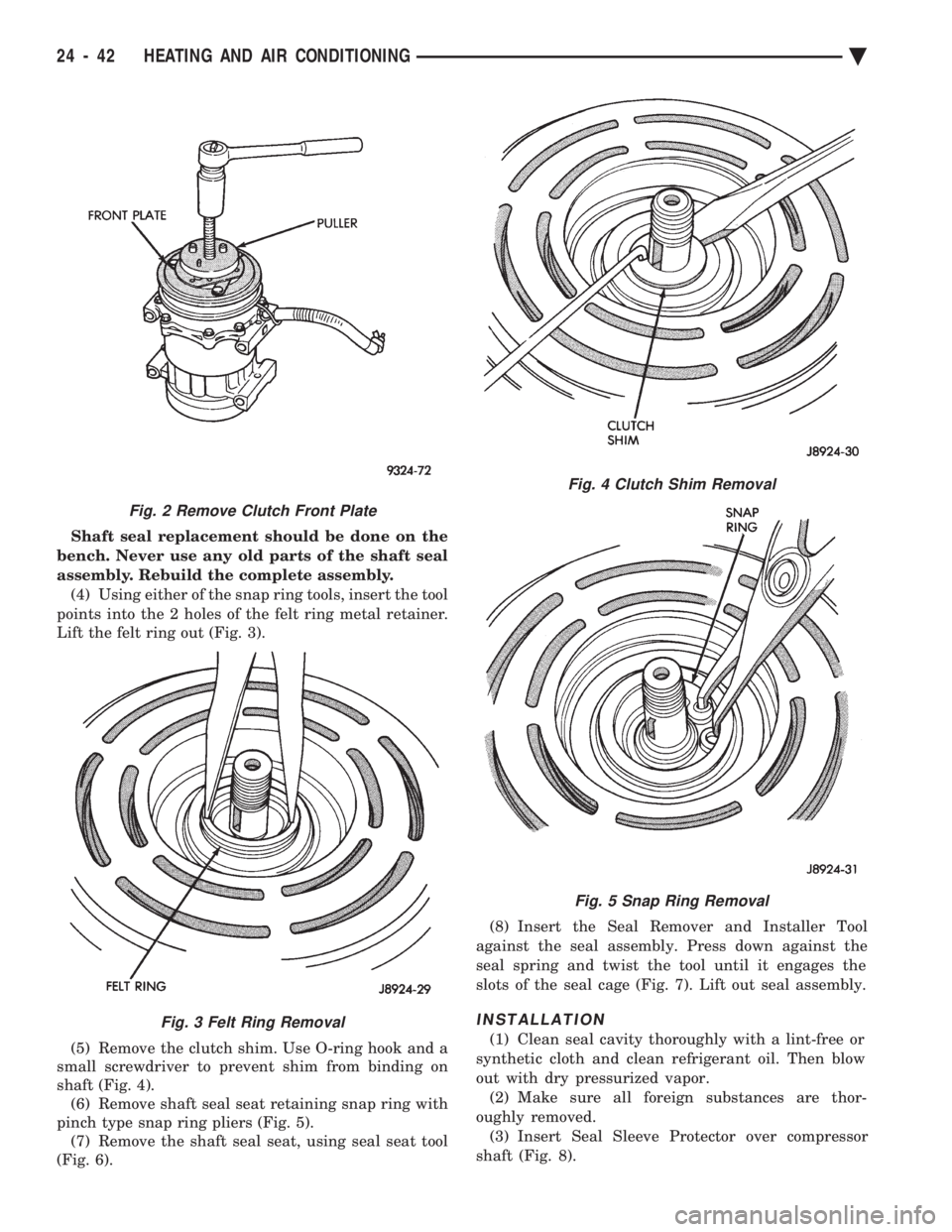
assembly. Rebuild the complete assembly. (4) Using either of the snap ring tools, insert the tool
points into the 2 holes of the felt ring metal retainer.
Lift the felt ring out (Fig. 3).
(5) Remove the clutch shim. Use O-ring hook and a
small screwdriver to prevent shim from binding on
shaft (Fig. 4). (6) Remove shaft seal seat retaining snap ring with
pinch type snap ring pliers (Fig. 5). (7) Remove the shaft seal seat, using seal seat tool
(Fig. 6). (8) Insert the Seal Remover and Installer Tool
against the seal assembly. Press down against the
seal spring and twist the tool until it engages the
slots of the seal cage (Fig. 7). Lift out seal assembly.
INSTALLATION
(1) Clean seal cavity thoroughly with a lint-free or
synthetic cloth and clean refrigerant oil. Then blow
out with dry pressurized vapor. (2) Make sure all foreign substances are thor-
oughly removed. (3) Insert Seal Sleeve Protector over compressor
shaft (Fig. 8).
Fig. 4 Clutch Shim Removal
Fig. 5 Snap Ring Removal
Fig. 2 Remove Clutch Front Plate
Fig. 3 Felt Ring Removal
24 - 42 HEATING AND AIR CONDITIONING Ä
Page 2362 of 2438

new condenser, refer to Oil Level in the Refrigerant
section. Tighten the refrigerant line mounting nut to
23 N Im (200 inch pounds).
Evacuate and recharge system.
BLOWER MOTOR
BLOWER MOTOR VIBRATION AND/OR NOISE DIAGNOSIS
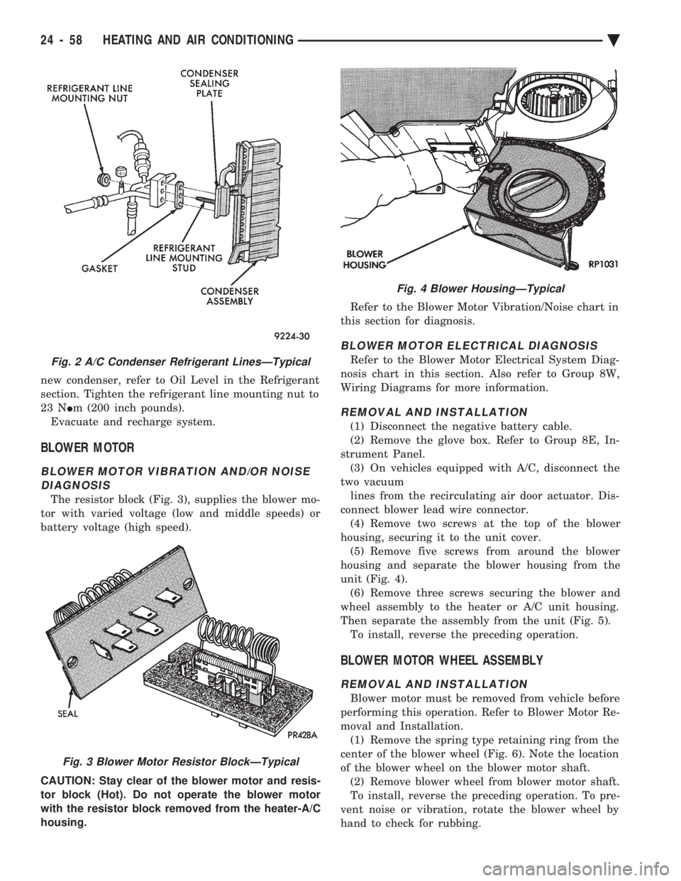
The resistor block (Fig. 3), supplies the blower mo-
tor with varied voltage (low and middle speeds) or
battery voltage (high speed).
CAUTION: Stay clear of the blower motor and resis-
tor block (Hot). Do not operate the blower motor
with the resistor block removed from the heater-A/C
housing. Refer to the Blower Motor Vibration/Noise chart in
this section for diagnosis.
BLOWER MOTOR ELECTRICAL DIAGNOSIS
Refer to the Blower Motor Electrical System Diag-
nosis chart in this section. Also refer to Group 8W,
Wiring Diagrams for more information.
REMOVAL AND INSTALLATION
(1) Disconnect the negative battery cable.
(2) Remove the glove box. Refer to Group 8E, In-
strument Panel. (3) On vehicles equipped with A/C, disconnect the
two vacuum lines from the recirculating air door actuator. Dis-
connect blower lead wire connector. (4) Remove two screws at the top of the blower
housing, securing it to the unit cover. (5) Remove five screws from around the blower
housing and separate the blower housing from the
unit (Fig. 4). (6) Remove three screws securing the blower and
wheel assembly to the heater or A/C unit housing.
Then separate the assembly from the unit (Fig. 5). To install, reverse the preceding operation.
BLOWER MOTOR WHEEL ASSEMBLY
REMOVAL AND INSTALLATION
Blower motor must be removed from vehicle before
performing this operation. Refer to Blower Motor Re-
moval and Installation. (1) Remove the spring type retaining ring from the
center of the blower wheel (Fig. 6). Note the location
of the blower wheel on the blower motor shaft. (2) Remove blower wheel from blower motor shaft.
To install, reverse the preceding operation. To pre-
vent noise or vibration, rotate the blower wheel by
hand to check for rubbing.
Fig. 2 A/C Condenser Refrigerant LinesÐTypical
Fig. 3 Blower Motor Resistor BlockÐTypical
Fig. 4 Blower HousingÐTypical
24 - 58 HEATING AND AIR CONDITIONING Ä