1993 CHEVROLET PLYMOUTH ACCLAIM oil type
[x] Cancel search: oil typePage 2053 of 2438
FLUID LEVEL AND CONDITION
The transmission and differential sump have a
common oil sump with a communicating opening
between the two. The torque converter fills in both the PPark and N
Neutral positions. Place the selector lever in PPark to
check the fluid level. The engine should be running
at idle speed for at least one minute, with the
vehicle on level ground. This will assure com-
plete oil level stabilization between differential
and transmission. The fluid should be at normal
operating temperature (approximately 82 C. or 180 F.).
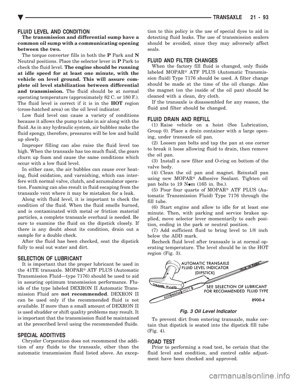
The fluid level is correct if it is in the HOTregion
(cross-hatched area) on the oil level indicator. Low fluid level can cause a variety of conditions
because it allows the pump to take in air along with the
fluid. As in any hydraulic system, air bubbles make the
fluid spongy, therefore, pressures will be low and build
up slowly. Improper filling can also raise the fluid level too
high. When the transaxle has too much fluid, the gears
churn up foam and cause the same conditions which
occur with a low fluid level. In either case, the air bubbles can cause over heat-
ing, fluid oxidation, and varnishing, which can inter-
fere with normal valve, clutch, and accumulator opera-
tion. Foaming can also result in fluid escaping from the
transaxle vent where it may be mistaken for a leak. Along with fluid level, it is important to check the
condition of the fluid. When the fluid smells burned,
and is contaminated with metal or friction material
particles, a complete transaxle overhaul is needed. Be
sure to examine the fluid on the dipstick closely. If
there is any doubt about its condition, drain out a
sample for a double check. After the fluid has been checked, seat the dipstick
fully to seal out water and dirt.
SELECTION OF LUBRICANT
It is important that the proper lubricant be used in
the 41TE transaxle. MOPAR tATF PLUS (Automatic
Transmission FluidÐtype 7176) should be used to aid
in assuring optimum transmission performance. Flu-
ids of the type labeled DEXRON II Automatic Trans-
mission Fluid are not recommended . DEXRON II
can be used only if the recommended fluid is not
available. If more than a small amount of DEXRON II
is used shudder or shift quality problems may result. It
is important that the transmission fluid be maintained
at the prescribed level using the recommended fluids.
SPECIAL ADDITIVES
Chrysler Corporation does not recommend the addi-
tion of any fluids to the transaxle, other than the
automatic transmission fluid listed above. An excep- tion to this policy is the use of special dyes to aid in
detecting fluid leaks. The use of transmission sealers
should be avoided, since they may adversely affect
seals.
FLUID AND FILTER CHANGES
When the factory fill fluid is changed, only fluids
labeled MOPAR tATF PLUS (Automatic Transmis-
sion fluid) Type 7176 should be used. A filter change
should be made at the time of the oil change. Also
the magnet (on the inside of the oil pan) should be
cleaned with a clean, dry cloth. If the transaxle is disassembled for any reason, the
fluid and filter should be changed.
FLUID DRAIN AND REFILL
(1) Raise vehicle on a hoist (See Lubrication,
Group 0). Place a drain container with a large open-
ing, under transaxle oil pan. (2) Loosen pan bolts and tap the pan at one corner
to break it loose allowing fluid to drain, then remove
the oil pan. (3) Install a new filter and O-ring on bottom of the
valve body. (4) Clean the oil pan and magnet. Reinstall pan
using new MOPAR tAdhesive Sealant. Tighten oil
pan bolts to 19 N Im (165 in. lbs.).
(5) Pour four quarts of MOPAR tATF PLUS (Au-
tomatic Transmission Fluid) Type 7176 through the
fill tube. (6) Start engine and allow to idle for at least one
minute. Then, with parking and service brakes ap-
plied, move selector lever momentarily to each posi-
tion, ending in the park or neutral position. (7) Add sufficient fluid to bring level to 1/8 inch
below the ADD mark. Recheck fluid level after transaxle is at normal op-
erating temperature. The level should be in the HOT
region (Fig. 3).
To prevent dirt from entering transaxle, make cer-
tain that dipstick is seated into the dipstick fill tube
(Fig. 4).
ROAD TEST
Prior to performing a road test, be certain that the
fluid level and condition, and control cable adjust-
ment have been checked and approved.
Fig. 3 Oil Level Indicator
Ä TRANSAXLE 21 - 93
Page 2059 of 2438
CAUTION: If the vehicle is equipped with two oil
coolers (one in the radiator tank, one in front of the
radiator) they must be flushed separately. Do not
attempt to flush both coolers at one time. (1) Disconnect the cooler lines at the transmission.
(2) Using a hand suction gun filled with mineral
spirits, reverse flush the cooler. Force mineral spirits
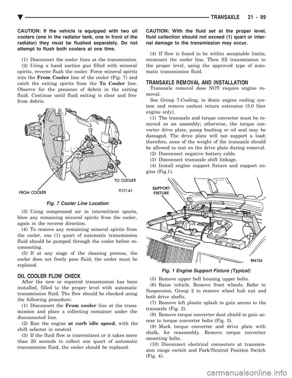
into the From Cooler line of the cooler (Fig. 7) and
catch the exiting spirits from the To Coolerline.
Observe for the presence of debris in the exiting
fluid. Continue until fluid exiting is clear and free
from debris.
(3) Using compressed air in intermittent spurts,
blow any remaining mineral spirits from the cooler,
again in the reverse direction. (4) To remove any remaining mineral spirits from
the cooler, one (1) quart of automatic transmission
fluid should be pumped through the cooler before re-
connecting. (5) If at any stage of the cleaning process, the
cooler does not freely pass fluid, the cooler must be
replaced.
OIL COOLER FLOW CHECK
After the new or repaired transmission has been
installed, filled to the proper level with automatic
transmission fluid. The flow should be checked using
the following procedure: (1) Disconnect the From coolerline at the trans-
mission and place a collecting container under the
disconnected line. (2) Run the engine at curb idle speed , with the
shift selector in neutral. (3) If the fluid flow is intermittent or it takes more
than 20 seconds to collect one quart of automatic
transmission fluid, the cooler should be replaced. CAUTION: With the fluid set at the proper level,
fluid collection should not exceed (1) quart or inter-
nal damage to the transmission may occur.
(4) If flow is found to be within acceptable limits,
reconnect the cooler line. Then fill transmission to
the proper level, using the approved type of auto-
matic transmission fluid.
TRANSAXLE REMOVAL AND INSTALLATION
Transaxle removal does NOT require engine re-
moval. See Group 7-Cooling, to drain engine cooling sys-
tem and remove coolant return extension (3.0 liter
engine only). (1) The transaxle and torque converter must be re-
moved as an assembly; otherwise, the torque con-
verter drive plate, pump bushing or oil seal may be
damaged. The drive plate will not support a load;
therefore, none of the weight of the transaxle should
be allowed to rest on the drive plate during removal. (2) Disconnect negative battery cable.
(3) Disconnect transaxle shift linkage.
(4) Install engine support fixture and support en-
gine (Fig.1).
(5) Remove upper bell housing upper bolts.
(6) Raise vehicle. Remove front wheels. Refer to
Suspension, Group 2 to remove wheel hub nut and
both drive shafts. (7) Remove left plastic splash to gain access to the
transaxle (Fig. 2). (8) Remove torque converter dust shield to gain ac-
cess to torque converter bolts (Fig. 3). (9) Mark torque converter and drive plate with
chalk, for reassembly. Remove torque converter
mounting bolts. (10) Disconnect electrical connectors at transmis-
sion range switch and Park/Neutral Position Switch
(Fig. 4).
Fig. 7 Cooler Line Location
Fig. 1 Engine Support Fixture (Typical)
Ä TRANSAXLE 21 - 99
Page 2149 of 2438
WHEELSÐTIRES
CONTENTS
page page
SPECIFICATIONS ........................ 8
TIRE SERVICE PROCEDURES .............. 1 WHEELS SERVICE PROCEDURES
........... 6
TIRE SERVICE PROCEDURES INDEX
page page
Cleaning of Tires .......................... 1
General Information ........................ 1
Pressure Gauges ......................... 2
Radial-Ply Tires ........................... 1
Repairing Leaks .......................... 3
Rotation ................................ 3 Spare TireÐCompact
...................... 1
Tire Inflation Pressures ..................... 2
Tire Noise or Vibration ..................... 3
Tire Wear Patterns ........................ 3
Tread Wear Indicators ...................... 3
GENERAL INFORMATION
Throughout this group, references may be made to a
particular vehicle by letter or number designation. A
chart showing the breakdown of these designations is
included in the Introduction Section. Tires are designed for the vehicle and provide the
best overall performance for normal operation. The
ride and handling characteristics match the vehicle's
requirements. With proper care they will give excellent
reliability traction, skid resistance and tread life. They
have load carrying capacity, when properly inflated, to
operate at loads up to the specified Maximum Vehicle
Capacity. Driving habits have more effect on tire life than any
other factor. Careful drivers will obtain, in most cases,
much greater mileage than severe or careless drivers. A
few of the driving habits which will shorten the life of
any tire are:
² Rapid acceleration and deceleration
² Severe application of brakes
² High-speed driving
² Taking turns at excessive speeds
² Striking curbs and other obstacles
Radial ply tires can be more susceptible to irregular
tread wear. It is very important to follow the tire
rotation interval shown in the section on Tire
Rotation to achieve a greater tread life potential.
RADIAL-PLY TIRES
Radial-ply tires improve handling, tread life, and
ride quality and decrease rolling resistance. Radial-ply tires must always be used in sets of four
and under no circumstances should they be used on
the front only. However, they may be mixed with temporary spare tires when necessary,
but reduced speeds are recommended. Radial-ply tires have the same load carrying capac-
ity as other types of tires of the same size. They also
use the same recommended inflation pressures.
SPARE TIREÐCOMPACT
The compact spare tire is designed for emergency
use only. The original tire should be repaired and re-
installed at the first opportunity. Refer to Owner's
Manual for complete details.
TIRE CHAINS
Tire snow chains may be used on certainmodels.
Refer to Owner's Manual for more information.
CLEANING OF TIRES
Remove protective coating on tires before delivery
of vehicle, otherwise it could cause deterioration of
tires. Remove protective coating by applying warm wa-
ter, letting it soak one minute, and then scrubbing
the coating away with a soft bristle brush. Steam cleaning may also be used for cleaning.
DO NOT use gasoline or wire brush for cleaning.
DO NOT use mineral oil or an oil-based solvent.
Ä WHEELSÐTIRES 22 - 1
Page 2307 of 2438
SAFETY PRECAUTIONS AND WARNINGS
WARNING: WEAR EYE PROTECTION WHEN SER-
VICING THE AIR CONDITIONING REFRIGERANT
SYSTEM. SERIOUS EYE INJURY CAN RESULT
FROM EYE CONTACT WITH REFRIGERANT. IF EYE
CONTACT IS MADE, SEEK MEDICAL ATTENTION
IMMEDIATELY. DO NOT EXPOSE REFRIGERANT TO OPEN
FLAME. POISONOUS GAS IS CREATED WHEN RE-
FRIGERANT IS BURNED. AN ELECTRONIC TYPE
LEAK DETECTOR IS RECOMMENDED. LARGE AMOUNTS OF REFRIGERANT RELEASED
IN A CLOSED WORK AREA WILL DISPLACE THE
OXYGEN AND CAUSE SUFFOCATION. THE EVAPORATION RATE OF (R-12) REFRIGER-
ANT AT AVERAGE TEMPERATURE AND ALTITUDE
IS EXTREMELY HIGH. AS A RESULT, ANYTHING
THAT COMES IN CONTACT WITH THE REFRIGER-
ANT WILL FREEZE. ALWAYS PROTECT SKIN OR
DELICATE OBJECTS FROM DIRECT CONTACT
WITH REFRIGERANT.
CAUTION: Liquid refrigerant is corrosive to metal
surfaces. Follow the operating instructions supplied
with equipment being used.
COOLING SYSTEM PRECAUTIONS
WARNING: ANTIFREEZE IS AN ETHYLENE GLYCOL
BASE COOLANT AND IS HARMFUL IF SWAL-
LOWED OR INHALED. IF SWALLOWED, DRINK
TWO GLASSES OF WATER AND INDUCE VOMIT-
ING. IF INHALED, MOVE TO FRESH AIR AREA.
SEEK MEDICAL ATTENTION IMMEDIATELY. DO NOT STORE IN OPEN OR UNMARKED CON-
TAINERS. WASH SKIN AND CLOTHING THOROUGHLY AF-
TER COMING IN CONTACT WITH ETHYLENE GLY-
COL. KEEP OUT OF REACH OF CHILDREN AND PETS.
DO NOT OPEN A COOLING SYSTEM WHEN THE
ENGINE IS AT RUNNING TEMPERATURE. PER-
SONAL INJURY CAN RESULT.
The engine cooling system is designed to develop
internal pressure of 97 to 123 kPa (14 to 18 psi). Al-
low the vehicle 15 minutes (or until a safe tempera-
ture and pressure are attained) before opening the
cooling system. Refer to Group 7, Cooling System.
HANDLING TUBING AND FITTINGS
Kinks in the refrigerant tubing or sharp bends in
the refrigerant hose lines will greatly reduce the ca-
pacity of the entire system. High pressures are pro-
duced in the system when it is operating. Extreme
care must be exercised to make sure that all connec-
tions are pressure tight. Dirt and moisture can enter
the system when it is opened for repair or replace-
ment of lines or components. The refrigerant oil will
absorb moisture readily out of the air. This moisture
will convert into acids within a closed system. The following precautions must be observed:
The system must be completely empty before open-
ing any fitting or connection in the refrigeration sys-
tem. Open fittings with caution even after the
system has been emptied. If any pressure is noticed
as a fitting is loosened, allow trapped pressure to
bleed off very slowly. A good rule for the flexible hose lines is to keep the
radius of all bends at least 10 times the diameter of
the hose. Sharper bends will reduce the flow of re-
frigerant. The flexible hose lines should be routed so
they are at least 3 inches (80 mm) from the exhaust
manifold. Inspect all flexible hose lines to make sure
they are in good condition and properly routed. Unified plumbing connections with aluminum gas-
kets cannot be serviced with O-rings. These gaskets
are not reusable and do not require lubrication be-
fore installing. The use of correct wrenches when making connec-
tions is very important. Improper wrenches or im-
proper use of wrenches can damage the fittings. The A/C system will remain chemical stabile as
long as pure-moisture-free R-12 and refrigerant oil is
used. Abnormal amounts of dirt, moisture or air can
upset the chemical stability. This condition could
cause operational troubles or even serious damage if
present in more than very small quantities. When it is necessary to open the refrigeration sys-
tem, have everything needed to service the system
ready. The system should not be left open any longer
than necessary. Cap or plug all lines and fittings as
soon as they are opened to prevent the entrance or
dirt and moisture. All lines and components in parts
stock should be capped or sealed until they are ready
to be used. All tools, including the refrigerant dispensing man-
ifold, the manifold gauge set, and test hoses should
be kept clean and dry.
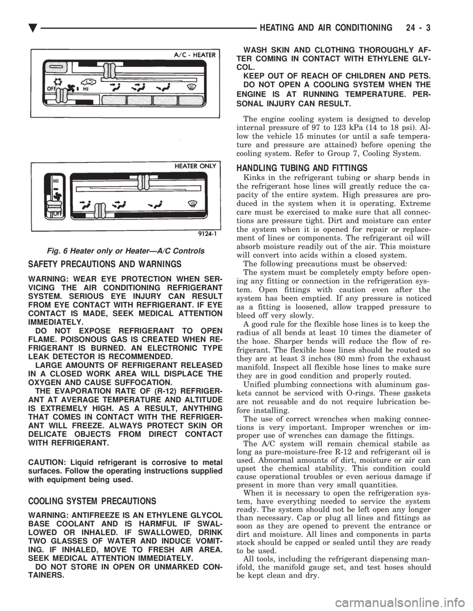
Fig. 6 Heater only or HeaterÐA/C Controls
Ä HEATING AND AIR CONDITIONING 24 - 3
Page 2312 of 2438
REFRIGERANT SERVICE PROCEDURES INDEX
page page
Adding Partial Refrigerant Charge ............ 10
Charging Refrigerant SystemÐEmpty System . . . 11
Discharging Refrigerant System .............. 11
Evacuating Refrigerant System .............. 11
Manifold Gauge Set Connections ............. 9 Oil Level
............................... 12
R-12 Refrigerant Equipment ................. 8
Refrigerant Recycling ...................... 9
Sight Glass Refrigerant Level Inspection ........ 8
Testing for Refrigerant Leaks ............... 10
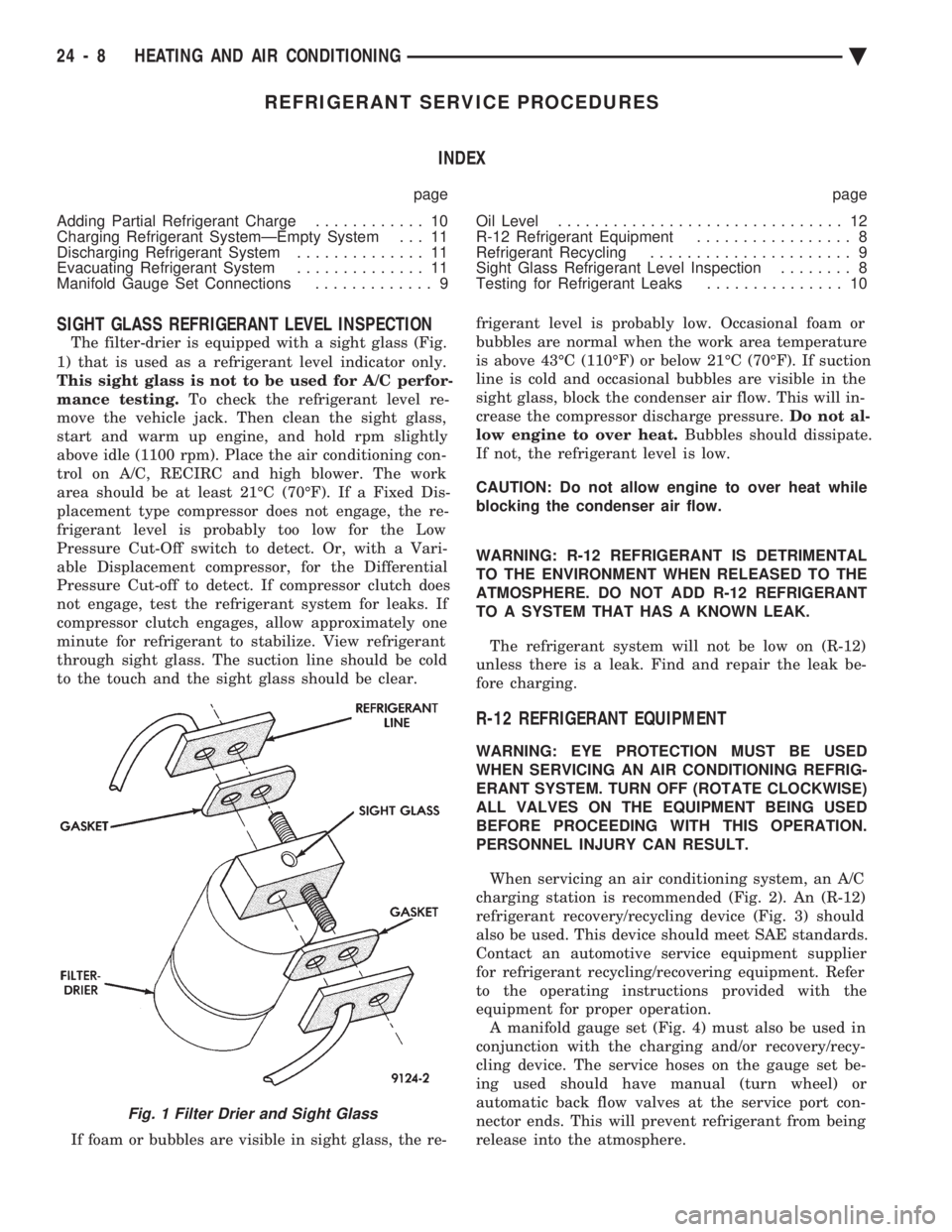
SIGHT GLASS REFRIGERANT LEVEL INSPECTION
The filter-drier is equipped with a sight glass (Fig.
1) that is used as a refrigerant level indicator only.
This sight glass is not to be used for A/C perfor-
mance testing. To check the refrigerant level re-
move the vehicle jack. Then clean the sight glass,
start and warm up engine, and hold rpm slightly
above idle (1100 rpm). Place the air conditioning con-
trol on A/C, RECIRC and high blower. The work
area should be at least 21ÉC (70ÉF). If a Fixed Dis-
placement type compressor does not engage, the re-
frigerant level is probably too low for the Low
Pressure Cut-Off switch to detect. Or, with a Vari-
able Displacement compressor, for the Differential
Pressure Cut-off to detect. If compressor clutch does
not engage, test the refrigerant system for leaks. If
compressor clutch engages, allow approximately one
minute for refrigerant to stabilize. View refrigerant
through sight glass. The suction line should be cold
to the touch and the sight glass should be clear.
If foam or bubbles are visible in sight glass, the re- frigerant level is probably low. Occasional foam or
bubbles are normal when the work area temperature
is above 43ÉC (110ÉF) or below 21ÉC (70ÉF). If suction
line is cold and occasional bubbles are visible in the
sight glass, block the condenser air flow. This will in-
crease the compressor discharge pressure. Do not al-
low engine to over heat. Bubbles should dissipate.
If not, the refrigerant level is low.
CAUTION: Do not allow engine to over heat while
blocking the condenser air flow.
WARNING: R-12 REFRIGERANT IS DETRIMENTAL
TO THE ENVIRONMENT WHEN RELEASED TO THE
ATMOSPHERE. DO NOT ADD R-12 REFRIGERANT
TO A SYSTEM THAT HAS A KNOWN LEAK.
The refrigerant system will not be low on (R-12)
unless there is a leak. Find and repair the leak be-
fore charging.
R-12 REFRIGERANT EQUIPMENT
WARNING: EYE PROTECTION MUST BE USED
WHEN SERVICING AN AIR CONDITIONING REFRIG-
ERANT SYSTEM. TURN OFF (ROTATE CLOCKWISE)
ALL VALVES ON THE EQUIPMENT BEING USED
BEFORE PROCEEDING WITH THIS OPERATION.
PERSONNEL INJURY CAN RESULT.
When servicing an air conditioning system, an A/C
charging station is recommended (Fig. 2). An (R-12)
refrigerant recovery/recycling device (Fig. 3) should
also be used. This device should meet SAE standards.
Contact an automotive service equipment supplier
for refrigerant recycling/recovering equipment. Refer
to the operating instructions provided with the
equipment for proper operation. A manifold gauge set (Fig. 4) must also be used in
conjunction with the charging and/or recovery/recy-
cling device. The service hoses on the gauge set be-
ing used should have manual (turn wheel) or
automatic back flow valves at the service port con-
nector ends. This will prevent refrigerant from being
release into the atmosphere.
Fig. 1 Filter Drier and Sight Glass
24 - 8 HEATING AND AIR CONDITIONING Ä
Page 2316 of 2438
WARNING: REVIEW SAFETY PRECAUTIONS AND
WARNINGS BEFORE CHARGING THE REFRIGER-
ANT SYSTEM.
After the system has been tested for leaks and
evacuated, a refrigerant charge can be injected into
the system. (1) Connect manifold gauge set.
(2) Measure refrigerant (refer to capacities) and
heat to 52ÉC (125ÉF) with the charging station. Refer
to the instructions provided with the equipment be-
ing used.
REFRIGERANT CAPACITIES:
² Without Rear A/C = 907 g (32 oz.)
² With Rear A/C = 1219 g (43 oz.)
(3) Open the suction and discharge valves. Open
the charge valve to allow the heated refrigerant to
flow into the system. When the transfer of refriger-
ant has stopped, close the suction and discharge
valve. (4) If all of the refrigerant charge did not transfer
from the dispensing device, start engine and hold at
idle (1400 rpm). Set the A/C control to A/C, low
blower speed, and open windows. If the A/C compres-
sor does not engage, test the compressor clutch con-
trol circuit and correct any failure. Refer to Group
8W, Wiring Diagrams. (5) Open the suction valve to allow the remaining
refrigerant to transfer to the system.
WARNING: TAKE CARE NOT TO OPEN THE DIS-
CHARGE (HIGH-PRESSURE) VALVE AT THIS TIME.
(6) Close all valves and test the A/C system perfor-
mance. Refer to Heater and A/C Performance Tests
in this Group. (7) Disconnect the charging station or manifold
gauge set. Install the service port caps.
OIL LEVEL
It is important to have the correct amount of oil in
the A/C system to ensure proper lubrication of the
compressor. Too little oil will result in damage to the
compressor. Too much oil will reduce the cooling ca-
pacity of the system. The oil used in the compressor is a 500 SUS viscos-
ity, wax-free refrigerant oil. Only refrigerant oil of
the same type should be used to service the system.
Do not use any other oil. The oil container should be
kept tightly capped until it is ready for use, and then
tightly capped after use to prevent contamination
from dirt and moisture. Refrigerant oil will quickly
absorb any moisture it comes in contact with. It will not be necessary to check oil level in the
compressor or to add oil unless there has been an oil
loss. This may be due to a ruptured line, shaft seal leakage, leakage from the evaporator, condenser
leak, filter drier or loss of refrigerant due to a colli-
sion. Oil loss at a the leak point will be evident by
the presence of a wet, shiny surface around the leak.
REFRIGERANT OIL LEVEL CHECK
When an A/C system is assembled at the factory,
all components (except the compressor) are refriger-
ant oil free. After the system has been charged with
R-12 and operated, the oil in the compressor is dis-
persed through the lines and components. The evap-
orator, condenser, and filter-drier will retain a
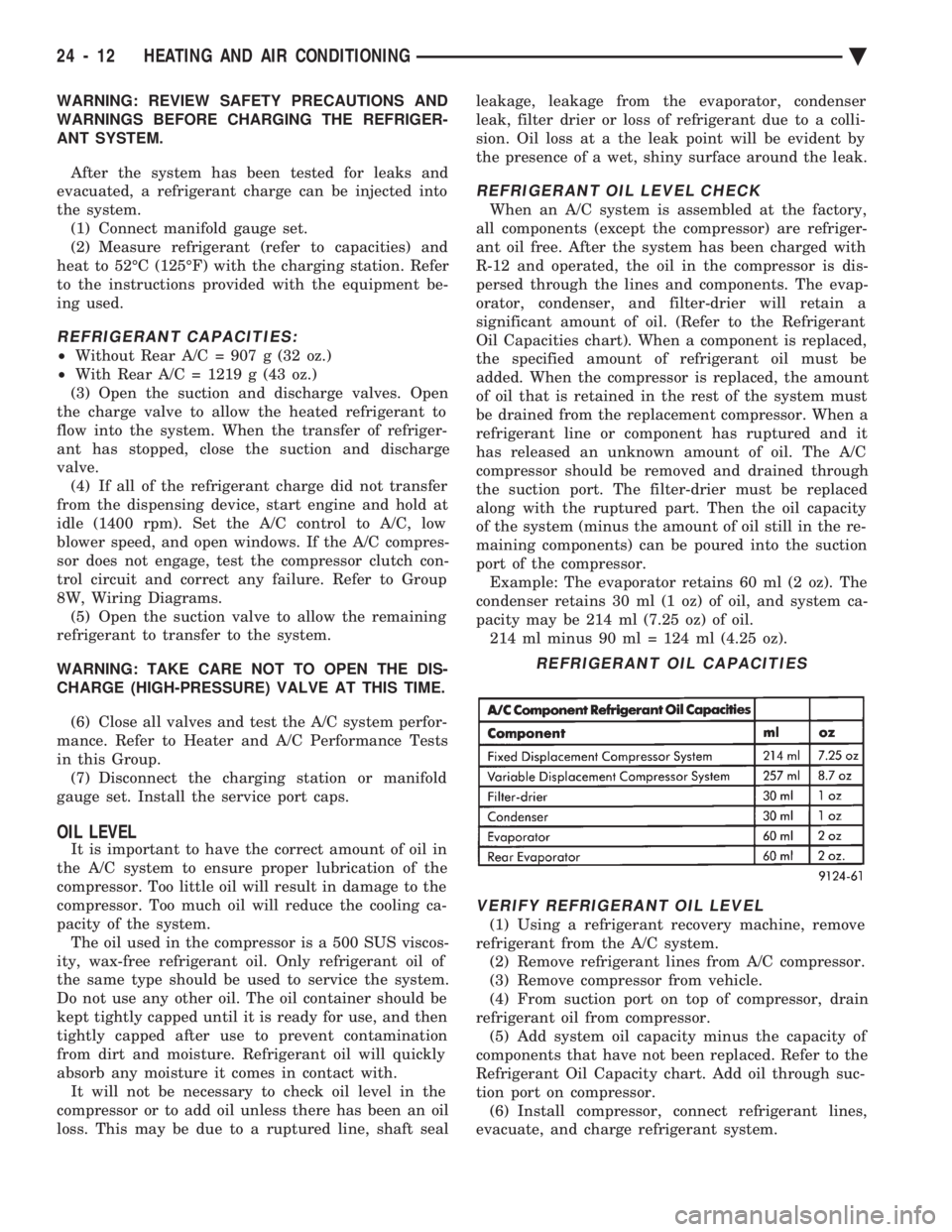
significant amount of oil. (Refer to the Refrigerant
Oil Capacities chart). When a component is replaced,
the specified amount of refrigerant oil must be
added. When the compressor is replaced, the amount
of oil that is retained in the rest of the system must
be drained from the replacement compressor. When a
refrigerant line or component has ruptured and it
has released an unknown amount of oil. The A/C
compressor should be removed and drained through
the suction port. The filter-drier must be replaced
along with the ruptured part. Then the oil capacity
of the system (minus the amount of oil still in the re-
maining components) can be poured into the suction
port of the compressor. Example: The evaporator retains 60 ml (2 oz). The
condenser retains 30 ml (1 oz) of oil, and system ca-
pacity may be 214 ml (7.25 oz) of oil. 214 ml minus 90 ml = 124 ml (4.25 oz).
VERIFY REFRIGERANT OIL LEVEL
(1) Using a refrigerant recovery machine, remove
refrigerant from the A/C system. (2) Remove refrigerant lines from A/C compressor.
(3) Remove compressor from vehicle.
(4) From suction port on top of compressor, drain
refrigerant oil from compressor. (5) Add system oil capacity minus the capacity of
components that have not been replaced. Refer to the
Refrigerant Oil Capacity chart. Add oil through suc-
tion port on compressor. (6) Install compressor, connect refrigerant lines,
evacuate, and charge refrigerant system.
REFRIGERANT OIL CAPACITIES
24 - 12 HEATING AND AIR CONDITIONING Ä
Page 2330 of 2438
REMOVAL
Compressor assembly must be removed from mount-
ing. Although, refrigerant removal is not necessary.
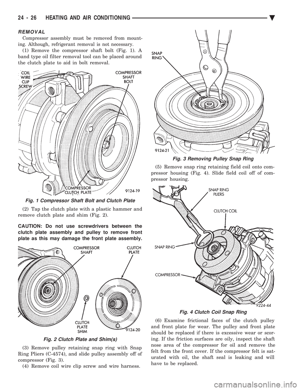
(1) Remove the compressor shaft bolt (Fig. 1). A
band type oil filter removal tool can be placed around
the clutch plate to aid in bolt removal.
(2) Tap the clutch plate with a plastic hammer and
remove clutch plate and shim (Fig. 2).
CAUTION: Do not use screwdrivers between the
clutch plate assembly and pulley to remove front
plate as this may damage the front plate assembly.
(3) Remove pulley retaining snap ring with Snap
Ring Pliers (C-4574), and slide pulley assembly off of
compressor (Fig. 3). (4) Remove coil wire clip screw and wire harness. (5) Remove snap ring retaining field coil onto com-
pressor housing (Fig. 4). Slide field coil off of com-
pressor housing.
(6) Examine frictional faces of the clutch pulley
and front plate for wear. The pulley and front plate
should be replaced if there is excessive wear or scor-
ing. If the friction surfaces are oily, inspect the shaft
nose area of the compressor for oil and remove the
felt from the front cover. If the compressor felt is sat-
urated with oil, the shaft seal is leaking and will
have to be replaced.
Fig. 1 Compressor Shaft Bolt and Clutch Plate
Fig. 2 Clutch Plate and Shim(s)
Fig. 3 Removing Pulley Snap Ring
Fig. 4 Clutch Coil Snap Ring
24 - 26 HEATING AND AIR CONDITIONING Ä
Page 2342 of 2438
FIXED DISPLACEMENT COMPRESSORÐMODEL SD709P INDEX
page page
Compressor ............................. 38
Compressor Clutch/Coil Assembly ............ 38
Compressor Shaft Seal .................... 41 Cylinder Head/Valve Plate
.................. 44
Description ............................. 38
Refrigerant System Diagnosis ............... 45
DESCRIPTION
The Sanden compressor is a 7 piston design. Sys-
tem lubrication is provided by 135 ml 615 ml (4.6 oz.
6 0.5 oz.) of 500 viscosity refrigerant oil.
The clutch used on the compressor consists of 3 ba-
sic components:
² The pulley
² Front plate
² Field coil
The pulley and field coil are attached to the front
head of the compressor with tapered snap rings. The
hub is keyed to the compressor shaft and is retained
on the shaft with a self-locking nut. Special service
tools are required to remove and install the clutch
plate on the compressor shaft.
COMPRESSOR
The A/C compressor may be removed and posi-
tioned without discharging the refrigerant system.
Discharging is not necessary if removing the A/C
compressor clutch/coil assembly, engine, cylinder
head, or generator.
WARNING: REFRIGERANT PRESSURES REMAIN
HIGH EVEN THOUGH THE ENGINE MAY BE
TURNED OFF. BEFORE REMOVING A FULLY
CHARGED COMPRESSOR, REVIEW THE SAFETY
PRECAUTIONS AND WARNINGS SECTION IN THIS
GROUP. DO NOT TWIST OR KINK THE REFRIGER-
ANT LINES WHEN REMOVING A FULLY CHARGED
COMPRESSOR. SAFETY GLASSES MUST BE
WORN.
REMOVAL
(1) Disconnect negative cable from battery.
(2) Loosen and remove drive belts (refer to group
7, Cooling System) and disconnect compressor clutch
wire lead. (3) Remove refrigerant lines from compressor (if
necessary). (4) Remove compressor attaching nuts and bolts.
(5) Remove compressor. If refrigerant lines were
not removed, lift compressor/clutch assembly and tie
it to a suitable component. To install, reverse the removal procedure.
COMPRESSOR CLUTCH/COIL ASSEMBLY
The magnetic clutch consists of a stationary elec-
tro-magnetic coil and a rotating pulley and plate as-
sembly. The electromagnetic coil is retained on the com-
pressor with a snap ring and is dimpled to maintain
its position. The pulley and plate assembly are mounted on the
compressor shaft. When the compressor is not in operation, the pul-
ley free wheels on the clutch hub bearing. When the
coil is energized the plate is magnetically engaged
with the pulley and turns the compressor shaft.
REMOVAL
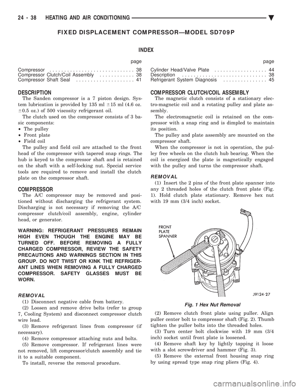
(1) Insert the 2 pins of the front plate spanner into
any 2 threaded holes of the clutch front plate (Fig.
1). Hold clutch plate stationary. Remove hex nut
with 19 mm (3/4 inch) socket.
(2) Remove clutch front plate using puller. Align
puller center bolt to compressor shaft (Fig. 2). Thumb
tighten the puller bolts into the threaded holes. (3) Turn center bolt clockwise with 19 mm (3/4
inch) socket until front plate is loosened. (4) Remove shaft key by lightly tapping it loose
with a slot screwdriver and hammer (Fig. 3). (5) Remove the external front housing snap ring
by using spread type snap ring pliers (Fig. 4).
Fig. 1 Hex Nut Removal
24 - 38 HEATING AND AIR CONDITIONING Ä