1993 CHEVROLET PLYMOUTH ACCLAIM remove seats
[x] Cancel search: remove seatsPage 2300 of 2438
(6) Pull trim panel forward and separate from ve-
hicle. (7) Remove bolt holding lap belt anchor to floor
and push end of belt through access hole in trim
panel.
INSTALLATION
Reverse the preceding operation.
REAR SHELF TRIM PANEL
REMOVAL (FIG. 25)
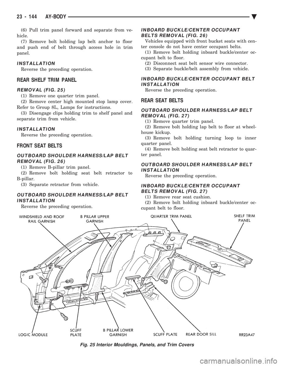
(1) Remove one quarter trim panel.
(2) Remove center high mounted stop lamp cover.
Refer to Group 8L, Lamps for instructions. (3) Disengage clips holding trim to shelf panel and
separate trim from vehicle.
INSTALLATION
Reverse the preceding operation.
FRONT SEAT BELTS
OUTBOARD SHOULDER HARNESS/LAP BELT REMOVAL (FIG. 26)
(1) Remove B-pillar trim panel.
(2) Remove bolt holding seat belt retractor to
B-pillar. (3) Separate retractor from vehicle.
OUTBOARD SHOULDER HARNESS/LAP BELTINSTALLATION
Reverse the preceding operation.
INBOARD BUCKLE/CENTER OCCUPANT BELTS REMOVAL (FIG. 26)
Vehicles equipped with front bucket seats with cen-
ter console do not have center occupant belts. (1) Remove bolt holding inboard buckle/center oc-
cupant belt to floor. (2) Disconnect seat belt sensor wire connector.
(3) Separate buckle/belt assembly from vehicle.
INBOARD BUCKLE/CENTER OCCUPANT BELT INSTALLATION
Reverse the preceding operation.
REAR SEAT BELTS
OUTBOARD SHOULDER HARNESS/LAP BELTREMOVAL (FIG. 27)
(1) Remove quarter trim panel.
(2) Remove bolt holding lap belt to floor at wheel-
house kickup. (3) Remove bolt holding turning loop to inner
quarter panel. (4) Remove bolt holding seat belt retractor to quar-
ter panel.
OUTBOARD SHOULDER HARNESS/LAP BELT INSTALLATION
Reverse the preceding operation.
INBOARD BUCKLE/CENTER OCCUPANTBELTS REMOVAL (FIG. 27)
(1) Remove rear seat cushion.
(2) Remove bolt holding inboard buckle/center oc-
cupant belt to floor.
Fig. 25 Interior Mouldings, Panels, and Trim Covers
23 - 144 AY-BODY Ä
Page 2301 of 2438
(3) Separate buckle/belt assembly from vehicle.
INBOARD BUCKLE/CENTER OCCUPANT BELT INSTALLATION
Reverse the preceding operation.
FRONT SEATS
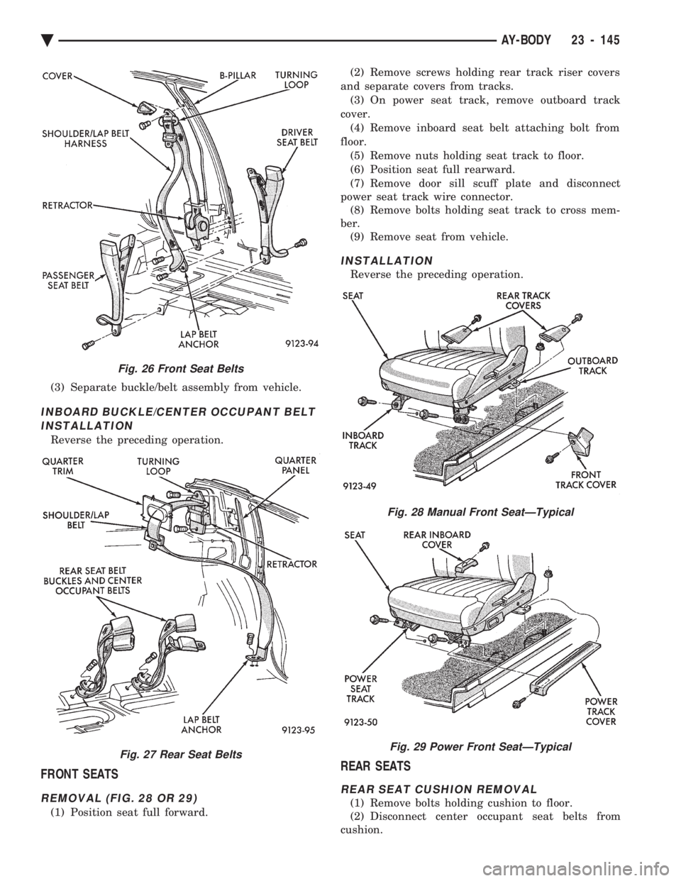
REMOVAL (FIG. 28 OR 29)
(1) Position seat full forward. (2) Remove screws holding rear track riser covers
and separate covers from tracks. (3) On power seat track, remove outboard track
cover. (4) Remove inboard seat belt attaching bolt from
floor. (5) Remove nuts holding seat track to floor.
(6) Position seat full rearward.
(7) Remove door sill scuff plate and disconnect
power seat track wire connector. (8) Remove bolts holding seat track to cross mem-
ber. (9) Remove seat from vehicle.
INSTALLATION
Reverse the preceding operation.
REAR SEATS
REAR SEAT CUSHION REMOVAL
(1) Remove bolts holding cushion to floor.
(2) Disconnect center occupant seat belts from
cushion.
Fig. 26 Front Seat Belts
Fig. 27 Rear Seat Belts
Fig. 28 Manual Front SeatÐTypical
Fig. 29 Power Front SeatÐTypical
Ä AY-BODY 23 - 145
Page 2323 of 2438
COMPRESSOR CLUTCH/COIL ASSEMBLY
Compressor assembly must be removed from
mounting. Refrigerant removal is not necessary to
replace the clutch/coil assembly. Refer to Compressor
Removal and Installation. On 3.0 liter engine, remove the front lower splash
shield and front engine mount through-bolt. Allow
the engine to swing down to provide access to the
front of the compressor. On 3.3 liter engine, remove the coolant recovery
bottle to provide access the front of the compressor.
REMOVAL AND INSTALLATION
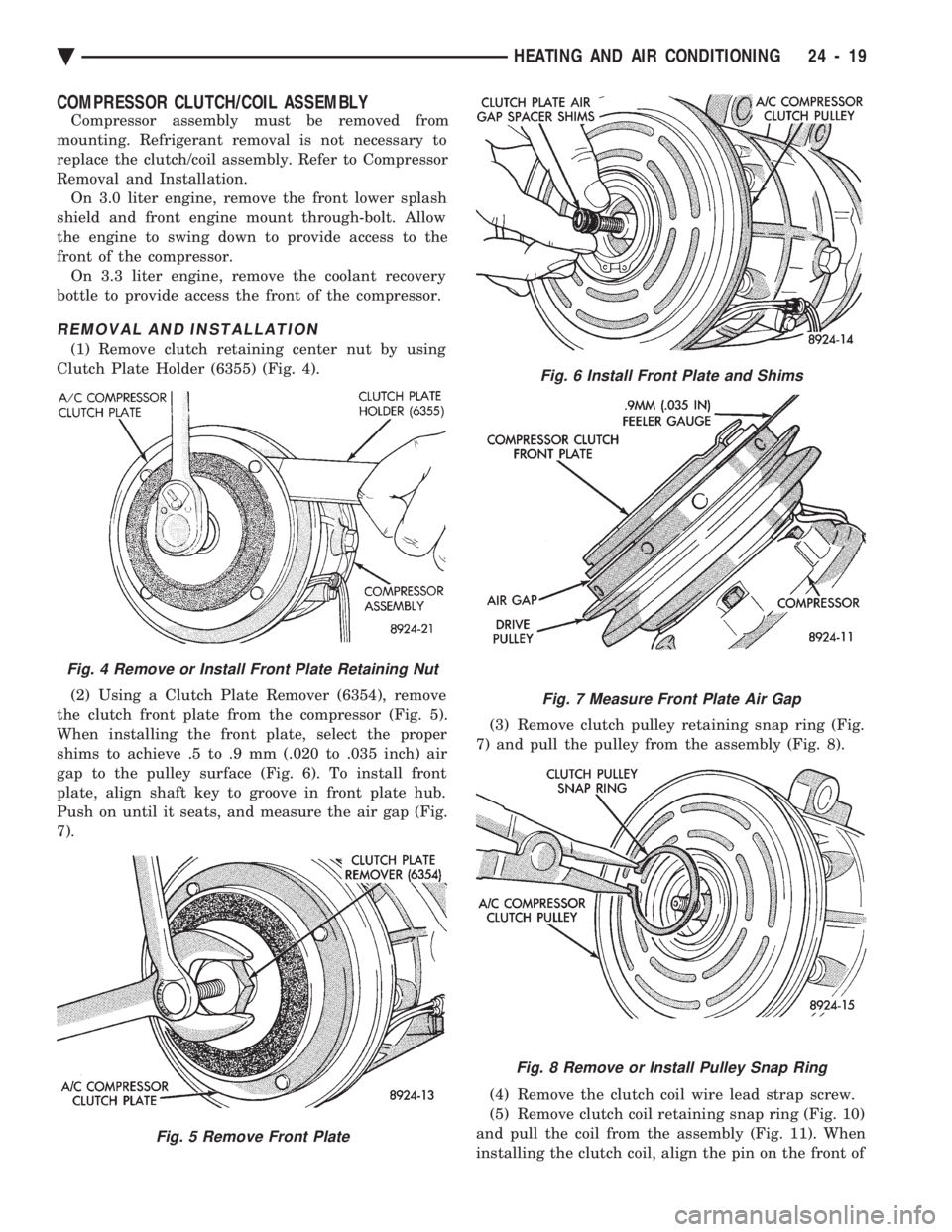
(1) Remove clutch retaining center nut by using
Clutch Plate Holder (6355) (Fig. 4).
(2) Using a Clutch Plate Remover (6354), remove
the clutch front plate from the compressor (Fig. 5).
When installing the front plate, select the proper
shims to achieve .5 to .9 mm (.020 to .035 inch) air
gap to the pulley surface (Fig. 6). To install front
plate, align shaft key to groove in front plate hub.
Push on until it seats, and measure the air gap (Fig.
7). (3) Remove clutch pulley retaining snap ring (Fig.
7) and pull the pulley from the assembly (Fig. 8).
(4) Remove the clutch coil wire lead strap screw.
(5) Remove clutch coil retaining snap ring (Fig. 10)
and pull the coil from the assembly (Fig. 11). When
installing the clutch coil, align the pin on the front of
Fig. 4 Remove or Install Front Plate Retaining Nut
Fig. 5 Remove Front Plate
Fig. 6 Install Front Plate and Shims
Fig. 7 Measure Front Plate Air Gap
Fig. 8 Remove or Install Pulley Snap Ring
Ä HEATING AND AIR CONDITIONING 24 - 19
Page 2324 of 2438
the compressor to the middle hole in the hub of the
coil. Position the pin in the snap ring gap.
To install, reverse the preceding operation.
COMPRESSOR FRONT SHAFT SEAL
REMOVAL
(1) Using a refrigerant recovery machine, remove
the refrigerant from the A/C system. (2) Remove A/C compressor.
(3) Remove the compressor clutch assembly and
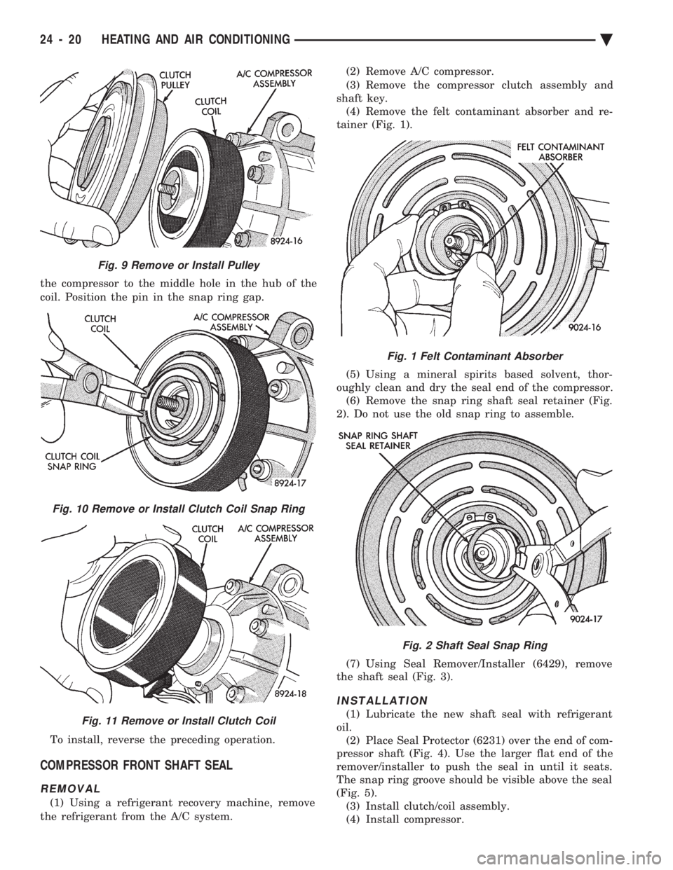
shaft key. (4) Remove the felt contaminant absorber and re-
tainer (Fig. 1).
(5) Using a mineral spirits based solvent, thor-
oughly clean and dry the seal end of the compressor. (6) Remove the snap ring shaft seal retainer (Fig.
2). Do not use the old snap ring to assemble.
(7) Using Seal Remover/Installer (6429), remove
the shaft seal (Fig. 3).
INSTALLATION
(1) Lubricate the new shaft seal with refrigerant
oil. (2) Place Seal Protector (6231) over the end of com-
pressor shaft (Fig. 4). Use the larger flat end of the
remover/installer to push the seal in until it seats.
The snap ring groove should be visible above the seal
(Fig. 5). (3) Install clutch/coil assembly.
(4) Install compressor.
Fig. 9 Remove or Install Pulley
Fig. 10 Remove or Install Clutch Coil Snap Ring
Fig. 11 Remove or Install Clutch Coil
Fig. 1 Felt Contaminant Absorber
Fig. 2 Shaft Seal Snap Ring
24 - 20 HEATING AND AIR CONDITIONING Ä
Page 2326 of 2438
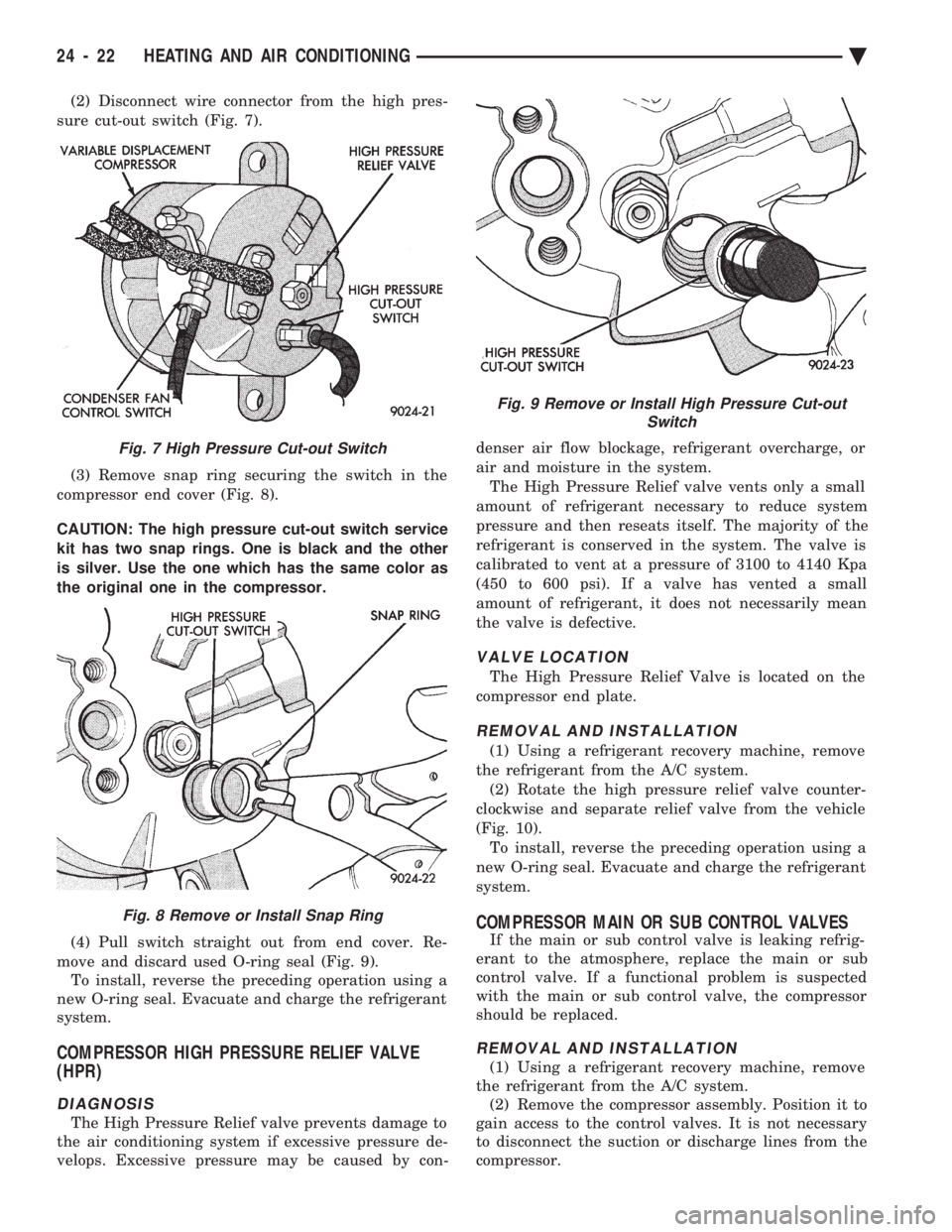
(2) Disconnect wire connector from the high pres-
sure cut-out switch (Fig. 7).
(3) Remove snap ring securing the switch in the
compressor end cover (Fig. 8).
CAUTION: The high pressure cut-out switch service
kit has two snap rings. One is black and the other
is silver. Use the one which has the same color as
the original one in the compressor.
(4) Pull switch straight out from end cover. Re-
move and discard used O-ring seal (Fig. 9). To install, reverse the preceding operation using a
new O-ring seal. Evacuate and charge the refrigerant
system.
COMPRESSOR HIGH PRESSURE RELIEF VALVE
(HPR)
DIAGNOSIS
The High Pressure Relief valve prevents damage to
the air conditioning system if excessive pressure de-
velops. Excessive pressure may be caused by con- denser air flow blockage, refrigerant overcharge, or
air and moisture in the system.
The High Pressure Relief valve vents only a small
amount of refrigerant necessary to reduce system
pressure and then reseats itself. The majority of the
refrigerant is conserved in the system. The valve is
calibrated to vent at a pressure of 3100 to 4140 Kpa
(450 to 600 psi). If a valve has vented a small
amount of refrigerant, it does not necessarily mean
the valve is defective.
VALVE LOCATION
The High Pressure Relief Valve is located on the
compressor end plate.
REMOVAL AND INSTALLATION
(1) Using a refrigerant recovery machine, remove
the refrigerant from the A/C system. (2) Rotate the high pressure relief valve counter-
clockwise and separate relief valve from the vehicle
(Fig. 10). To install, reverse the preceding operation using a
new O-ring seal. Evacuate and charge the refrigerant
system.
COMPRESSOR MAIN OR SUB CONTROL VALVES
If the main or sub control valve is leaking refrig-
erant to the atmosphere, replace the main or sub
control valve. If a functional problem is suspected
with the main or sub control valve, the compressor
should be replaced.
REMOVAL AND INSTALLATION
(1) Using a refrigerant recovery machine, remove
the refrigerant from the A/C system. (2) Remove the compressor assembly. Position it to
gain access to the control valves. It is not necessary
to disconnect the suction or discharge lines from the
compressor.
Fig. 7 High Pressure Cut-out Switch
Fig. 8 Remove or Install Snap Ring
Fig. 9 Remove or Install High Pressure Cut-out Switch
24 - 22 HEATING AND AIR CONDITIONING Ä
Page 2334 of 2438
CAUTION: Refer to Oil Level in the Refrigerant Ser-
vice Procedures section for further details. (13) Install refrigeration oil (500 SUS) into the
compressor through the suction port. (14) Check compressor operation for smoothness by
rotating crankshaft at least five full revolutions. (15) Check front housing clutch coil alignment pin
for proper installation. (16) Install clutch assembly.
(17) Install compressor.
(18) Evacuate and charge refrigerant system.
COMPRESSOR HIGH-PRESSURE RELIEF VALVE
The high pressure relief valve vents only a small
amount of refrigerant necessary to reduce system
pressure and then reseats itself. The majority of the
refrigerant is conserved in the system. The valve is
calibrated to vent at a pressure of 3100 to 4140 Kpa
(450 to 600 psi). If a valve has vented a small amount of refrigerant, it does not necessarily mean
the valve is defective.
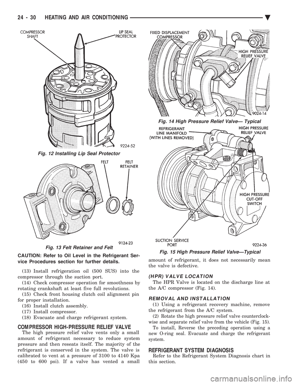
(HPR) VALVE LOCATION
The HPR Valve is located on the discharge line at
the A/C compressor (Fig. 14).
REMOVAL AND INSTALLATION
(1) Using a refrigerant recovery machine, remove
the refrigerant from the A/C system.
(2) Rotate the high pressure relief valve counterclock-
wise and separate relief valve from the vehicle (Fig. 15). To install, Reverse the preceding operation using a
new O-ring seal. Evacuate and charge the refrigerant
system.
REFRIGERANT SYSTEM DIAGNOSIS
Refer to the Refrigerant System Diagnosis chart in
this section.
Fig. 13 Felt Retainer and Felt
Fig. 14 High Pressure Relief ValveÐ Typical
Fig. 15 High Pressure Relief ValveÐTypical
Fig. 12 Installing Lip Seal Protector
24 - 30 HEATING AND AIR CONDITIONING Ä