1993 CHEVROLET PLYMOUTH ACCLAIM remove seats
[x] Cancel search: remove seatsPage 2235 of 2438
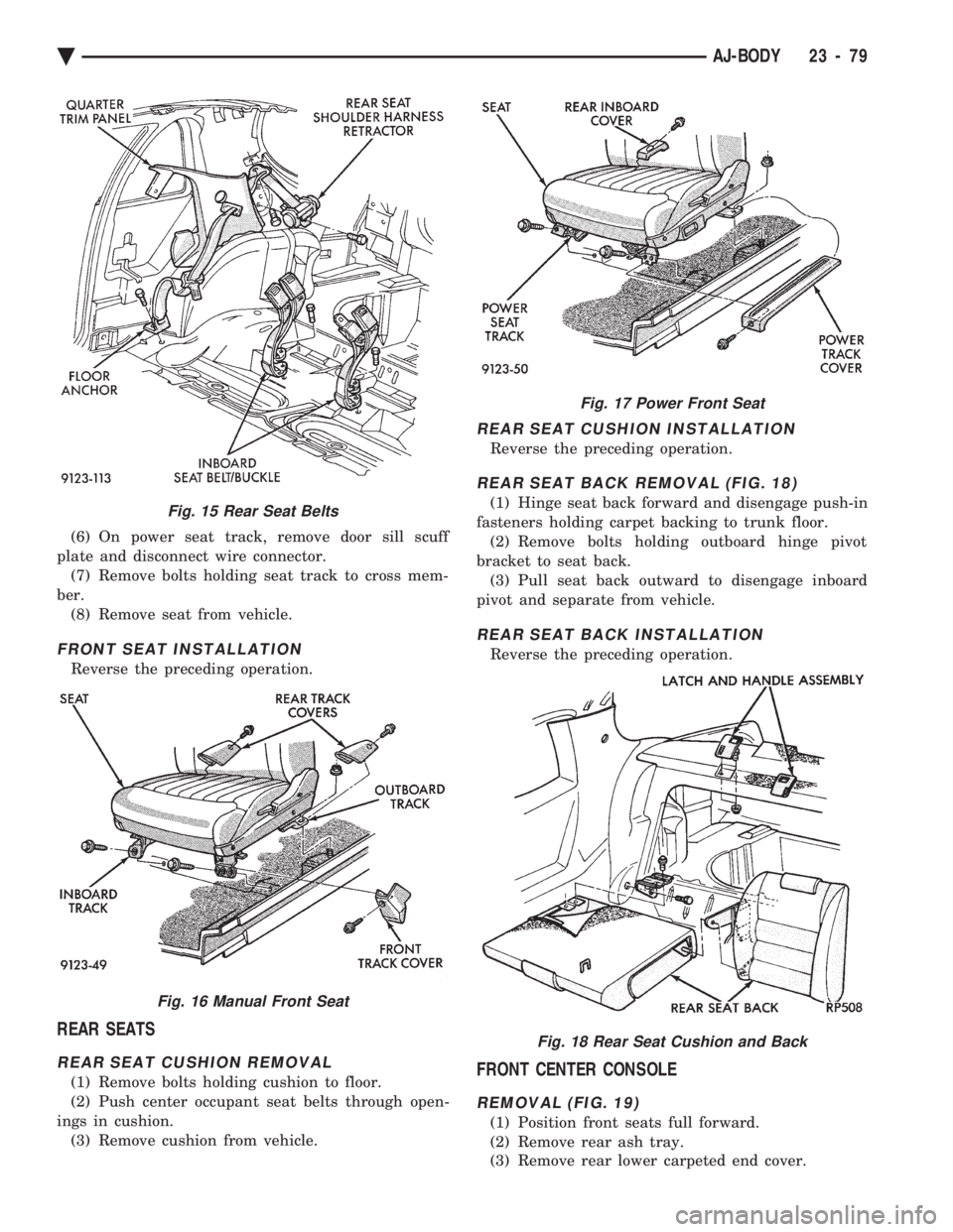
(6) On power seat track, remove door sill scuff
plate and disconnect wire connector. (7) Remove bolts holding seat track to cross mem-
ber. (8) Remove seat from vehicle.
FRONT SEAT INSTALLATION
Reverse the preceding operation.
REAR SEATS
REAR SEAT CUSHION REMOVAL
(1) Remove bolts holding cushion to floor.
(2) Push center occupant seat belts through open-
ings in cushion. (3) Remove cushion from vehicle.
REAR SEAT CUSHION INSTALLATION
Reverse the preceding operation.
REAR SEAT BACK REMOVAL (FIG. 18)
(1) Hinge seat back forward and disengage push-in
fasteners holding carpet backing to trunk floor. (2) Remove bolts holding outboard hinge pivot
bracket to seat back. (3) Pull seat back outward to disengage inboard
pivot and separate from vehicle.
REAR SEAT BACK INSTALLATION
Reverse the preceding operation.
FRONT CENTER CONSOLE
REMOVAL (FIG. 19)
(1) Position front seats full forward.
(2) Remove rear ash tray.
(3) Remove rear lower carpeted end cover.
Fig. 15 Rear Seat Belts
Fig. 16 Manual Front Seat
Fig. 17 Power Front Seat
Fig. 18 Rear Seat Cushion and Back
Ä AJ-BODY 23 - 79
Page 2236 of 2438
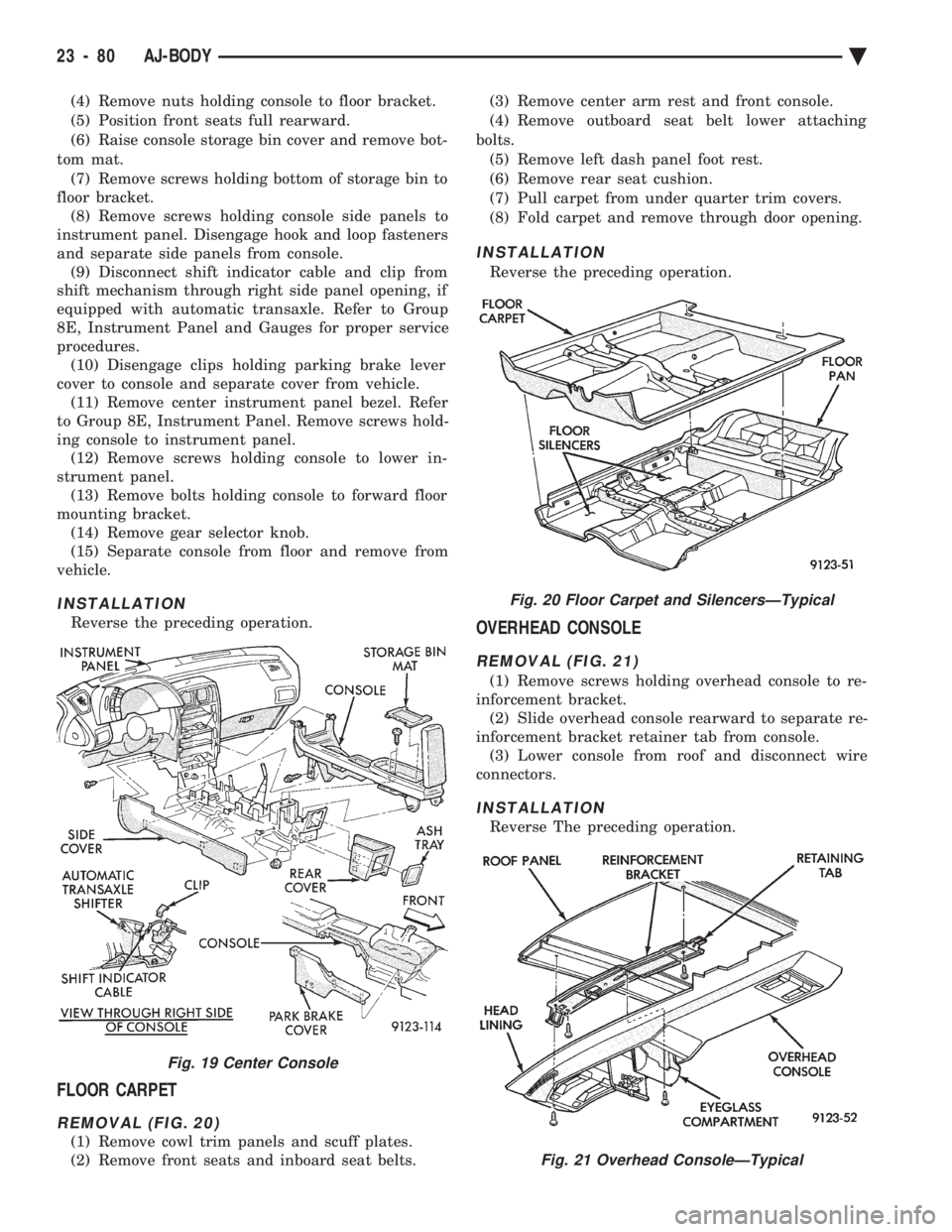
(4) Remove nuts holding console to floor bracket.
(5) Position front seats full rearward.
(6) Raise console storage bin cover and remove bot-
tom mat. (7) Remove screws holding bottom of storage bin to
floor bracket. (8) Remove screws holding console side panels to
instrument panel. Disengage hook and loop fasteners
and separate side panels from console. (9) Disconnect shift indicator cable and clip from
shift mechanism through right side panel opening, if
equipped with automatic transaxle. Refer to Group
8E, Instrument Panel and Gauges for proper service
procedures. (10) Disengage clips holding parking brake lever
cover to console and separate cover from vehicle. (11) Remove center instrument panel bezel. Refer
to Group 8E, Instrument Panel. Remove screws hold-
ing console to instrument panel. (12) Remove screws holding console to lower in-
strument panel. (13) Remove bolts holding console to forward floor
mounting bracket. (14) Remove gear selector knob.
(15) Separate console from floor and remove from
vehicle.
INSTALLATION
Reverse the preceding operation.
FLOOR CARPET
REMOVAL (FIG. 20)
(1) Remove cowl trim panels and scuff plates.
(2) Remove front seats and inboard seat belts. (3) Remove center arm rest and front console.
(4) Remove outboard seat belt lower attaching
bolts. (5) Remove left dash panel foot rest.
(6) Remove rear seat cushion.
(7) Pull carpet from under quarter trim covers.
(8) Fold carpet and remove through door opening.
INSTALLATION
Reverse the preceding operation.
OVERHEAD CONSOLE
REMOVAL (FIG. 21)
(1) Remove screws holding overhead console to re-
inforcement bracket. (2) Slide overhead console rearward to separate re-
inforcement bracket retainer tab from console. (3) Lower console from roof and disconnect wire
connectors.
INSTALLATION
Reverse The preceding operation.
Fig. 19 Center Console
Fig. 20 Floor Carpet and SilencersÐTypical
Fig. 21 Overhead ConsoleÐTypical
23 - 80 AJ-BODY Ä
Page 2253 of 2438
AP-VEHICLE BODY COMPONENT SERVICE INDEX
page page
A-Pillar and Roof Rail Mouldings ............ 109
B-Pillar Trim PanelÐAP-44 Body ............ 109
Body Side Moulding and Applique ........... 108
Cowl Panel Trim and Scuff Plates ........... 109
Door Opening Weatherstrips ............... 107
Floor Carpet ........................... 113
Front Center Console .................... 113
Front Door and Hinge .................... 100
Front Door Belt Moulding and Weatherstrip .... 102
Front Door Glass ........................ 101
Front Door Glass Channel and Run Weatherstrip .......................... 103
Front Door Glass Run Lower Channels ....... 103
Front Door Latch ........................ 101
Front Door Side View Mirror ............... 101
Front Door Trim PanelÐAP-24/44 Body ....... 99
Front Door Water Shield .................. 100
Front Door Window Regulator/Manual ........ 103
Front Door Window Regulator/Power ......... 104
Front End Splash Shields .................. 99
Front Power Door Lock Actuator ............ 102
Front Seat BeltsÐAP-24 Body .............. 110
Front Seat BeltsÐAP-44 Body .............. 110
Front Seats ............................ 111
Grille .................................. 97
Grille Opening Panel ...................... 97
Head Lining ............................ 114
Hood and Hinges ........................ 97 Hood Latch and Release Cable
.............. 98
Lift Gate Luggage Rack ................... 116
Lift Gate Remote Release Cable ............ 115
Lower Quarter Trim PanelÐAP-44 Body ...... 109
Outside Front Door Latch Release Handle ..... 101
Outside Rear Door Latch Release Handle ..... 105
Overhead Console ....................... 113
Quarter Glass Weatherstrip ................ 108
Quarter Glass Window ................... 108
Quarter Trim PanelÐAP-44 Body ........... 109
Rear Door and Hinge .................... 104
Rear Door Belt Moulding and Weatherstrip .... 106
Rear Door Glass ........................ 106
Rear Door Glass Run Weatherstrip .......... 107
Rear Door Latch ........................ 105
Rear Door Silencer and Water Shield ........ 104
Rear Door Stationary Glass ................ 107
Rear Door Trim Panel .................... 104
Rear Door Window Regulator/Manual ........ 107
Rear Door Window Regulator/Power ......... 107
Rear Power Door Lock Actuator ............ 106
Rear Seat Belts ......................... 111
Rear Seats ............................ 112
Rear Window Glass ...................... 115
Sun Roof Air Deflector ................... 114
Sun Roof Drain Tubes .................... 115
Sun Roof Weatherstrip ................... 114
Upper Quarter Trim PanelÐAP-44 Body ...... 109
GRILLE
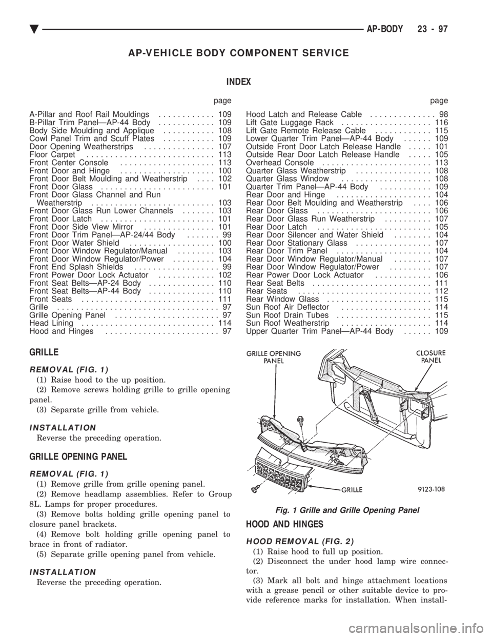
REMOVAL (FIG. 1)
(1) Raise hood to the up position.
(2) Remove screws holding grille to grille opening
panel. (3) Separate grille from vehicle.
INSTALLATION
Reverse the preceding operation.
GRILLE OPENING PANEL
REMOVAL (FIG. 1)
(1) Remove grille from grille opening panel.
(2) Remove headlamp assemblies. Refer to Group
8L. Lamps for proper procedures. (3) Remove bolts holding grille opening panel to
closure panel brackets. (4) Remove bolt holding grille opening panel to
brace in front of radiator. (5) Separate grille opening panel from vehicle.
INSTALLATION
Reverse the preceding operation.
HOOD AND HINGES
HOOD REMOVAL (FIG. 2)
(1) Raise hood to full up position.
(2) Disconnect the under hood lamp wire connec-
tor. (3) Mark all bolt and hinge attachment locations
with a grease pencil or other suitable device to pro-
vide reference marks for installation. When install-
Fig. 1 Grille and Grille Opening Panel
Ä AP-BODY 23 - 97
Page 2259 of 2438
FRONT DOOR GLASS CHANNEL AND RUN
WEATHERSTRIP
GLASS CHANNEL AND RUN WEATHERSTRIP
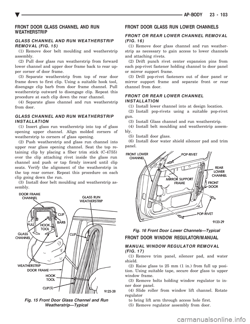
REMOVAL (FIG. 15)
(1) Remove door belt moulding and weatherstrip
assembly. (2) Pull door glass run weatherstrip from forward
lower channel and upper door frame back to rear up-
per corner of door frame. (3) Separate weatherstrip from top of rear door
frame down to first clip. Using a suitable hook tool,
disengage clip barb from door frame channel. Pull
weatherstrip outward to disengage clip. Repeat this
procedure at each clip down the rear channel. (4) Separate glass channel and run weatherstrip
from door.
GLASS CHANNEL AND RUN WEATHERSTRIP INSTALLATION
(1) Insert glass run weatherstrip into top of glass
opening upper channel. Align molded corners of
weatherstrip to corners of glass opening. (2) Push weatherstrip and glass run channel into
upper rear glass opening channel. Seat the top re-
taining clip by placing a fiber trim stick (C-4755)
over the clip attaching rivet inside the glass run
channel and push or tap firmly inward until clip
seats. Verify the alignment of the weatherstrip in
the top rear corner. Repeat this procedure on each
clip going down the run. (3) Install door belt moulding and weatherstrip as-
sembly.
FRONT DOOR GLASS RUN LOWER CHANNELS
FRONT OR REAR LOWER CHANNEL REMOVAL
(FIG. 16)
(1) Remove door glass channel and run weather-
strip as necessary to gain access to lower channels
and attaching rivets. (2) Drift punch rivet center expansion pins from
each pop-rivet fastener holding channel to door panel
or mirror support frame. (3) Drill pop-rivet fasteners out of door panel or
mirror support frame and separate front or rear
channel from door.
FRONT OR REAR LOWER CHANNEL INSTALLATION
(1) Install lower channel into at design location.
(2) Install pop-rivets using a suitable pop-rivet
gun. (3) Install Glass channel and run weatherstrip.
(4) Install belt moulding and weatherstrip assem-
bly. (5) Install door glass.
(6) Install door water shield silencer pad and trim
panel.
FRONT DOOR WINDOW REGULATOR/MANUAL
MANUAL WINDOW REGULATOR REMOVAL (FIG. 17)
(1) Remove trim panel, silencer pad, and water
shield. (2) Raise glass to 25 mm (1 in.) from full up posi-
tion. Using suitable tape, secure door glass to upper
window frame. (3) Remove bolts holding window regulator to in-
ner door panel. (4) Slide roller from window lift channel. Rotate
regulator to bring lift arm through access hole first.
(5) Remove regulator assembly from door.
Fig. 15 Front Door Glass Channel and Run WeatherstripÐTypical
Fig. 16 Front Door Lower ChannelsÐTypical
Ä AP-BODY 23 - 103
Page 2267 of 2438
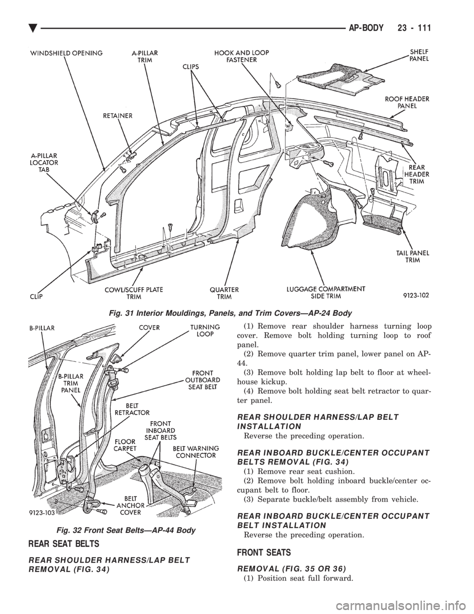
REAR SEAT BELTS
REAR SHOULDER HARNESS/LAP BELT REMOVAL (FIG. 34)
(1) Remove rear shoulder harness turning loop
cover. Remove bolt holding turning loop to roof
panel. (2) Remove quarter trim panel, lower panel on AP-
44. (3) Remove bolt holding lap belt to floor at wheel-
house kickup. (4) Remove bolt holding seat belt retractor to quar-
ter panel.
REAR SHOULDER HARNESS/LAP BELT INSTALLATION
Reverse the preceding operation.
REAR INBOARD BUCKLE/CENTER OCCUPANTBELTS REMOVAL (FIG. 34)
(1) Remove rear seat cushion.
(2) Remove bolt holding inboard buckle/center oc-
cupant belt to floor. (3) Separate buckle/belt assembly from vehicle.
REAR INBOARD BUCKLE/CENTER OCCUPANTBELT INSTALLATION
Reverse the preceding operation.
FRONT SEATS
REMOVAL (FIG. 35 OR 36)
(1) Position seat full forward.
Fig. 31 Interior Mouldings, Panels, and Trim CoversÐAP-24 Body
Fig. 32 Front Seat BeltsÐAP-44 Body
Ä AP-BODY 23 - 111
Page 2268 of 2438
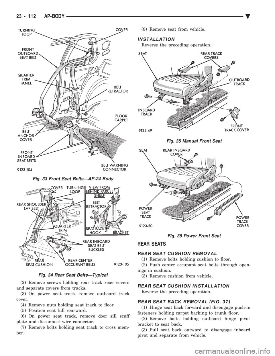
(2) Remove screws holding rear track riser covers
and separate covers from tracks. (3) On power seat track, remove outboard track
cover. (4) Remove nuts holding seat track to floor.
(5) Position seat full rearward.
(6) On power seat track, remove door sill scuff
plate and disconnect wire connector. (7) Remove bolts holding seat track to cross mem-
ber. (8) Remove seat from vehicle.
INSTALLATION
Reverse the preceding operation.
REAR SEATS
REAR SEAT CUSHION REMOVAL
(1) Remove bolts holding cushion to floor.
(2) Push center occupant seat belts through open-
ings in cushion. (3) Remove cushion from vehicle.
REAR SEAT CUSHION INSTALLATION
Reverse the preceding operation.
REAR SEAT BACK REMOVAL (FIG. 37)
(1) Hinge seat back forward and disengage push-in
fasteners holding carpet backing to trunk floor. (2) Remove bolts holding outboard hinge pivot
bracket to seat back. (3) Pull seat back outward to disengage inboard
pivot and separate from vehicle.
Fig. 33 Front Seat BeltsÐAP-24 Body
Fig. 34 Rear Seat BeltsÐTypical
Fig. 35 Manual Front Seat
Fig. 36 Power Front Seat
23 - 112 AP-BODY Ä
Page 2269 of 2438
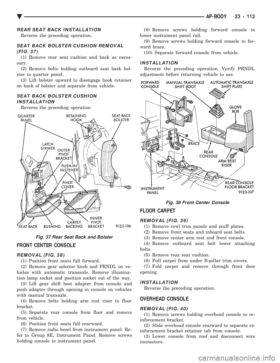
REAR SEAT BACK INSTALLATION
Reverse the preceding operation.
SEAT BACK BOLSTER CUSHION REMOVAL (FIG. 37)
(1) Remove rear seat cushion and back as neces-
sary. (2) Remove bolts holding outboard seat back bol-
ster to quarter panel. (3) Lift bolster upward to disengage hook retainer
on back of bolster and separate from vehicle.
SEAT BACK BOLSTER CUSHION INSTALLATION
Reverse the preceding operation
FRONT CENTER CONSOLE
REMOVAL (FIG. 38)
(1) Position front seats full forward.
(2) Remove gear selector knob and PRNDL on ve-
hicles with automatic transaxle. Remove illumina-
tion lamp socket and position socket out of the way. (3) Lift gear shift boot adapter from console and
push adapter through opening in console on vehicles
with manual transaxle. (4) Remove bolts holding arm rest riser to floor
bracket. (5) Separate rear console from floor and remove
from vehicle. (6) Position front seats full rearward.
(7) Remove radio bezel from instrument panel. Re-
fer to Group 8E, Instrument Panel. Remove screws
holding console to instrument panel. (8) Remove screws holding forward console to
lower instrument panel rail. (9) Remove screws holding forward console to for-
ward brace. (10) Separate forward console from vehicle.
INSTALLATION
Reverse the preceding operation. Verify PRNDL
adjustment before returning vehicle to use.
FLOOR CARPET
REMOVAL (FIG. 39)
(1) Remove cowl trim panels and scuff plates.
(2) Remove front seats and inboard seat belts.
(3) Remove center arm rest and front console.
(4) Remove outboard seat belt lower attaching
bolts. (5) Remove rear seat cushion.
(6) Pull carpet from under B-pillar trim covers.
(7) Fold carpet and remove through front door
opening.
INSTALLATION
Reverse the preceding operation.
OVERHEAD CONSOLE
REMOVAL (FIG. 40)
(1) Remove screws holding overhead console to re-
inforcement bracket. (2) Slide overhead console rearward to separate re-
inforcement bracket retainer tab from console. (3) Lower console from roof and disconnect wire
connectors.
Fig. 37 Rear Seat Back and Bolster
Fig. 38 Front Center Console
Ä AP-BODY 23 - 113
Page 2289 of 2438
AY-VEHICLE BODY COMPONENT SERVICE INDEX
page page
A-Pillar and Roof Rail Mouldings ............ 143
B-Pillar Trim Panel ...................... 143
Body Mouldings ......................... 146
Cowl Panel Trim and Scuff Plates ........... 143
Door Frame Trim Moulding ................ 137
Front Door and Hinge .................... 137
Front Door Glass ........................ 139
Front Door Latch ........................ 138
Front Door Silencer and Water Shield ........ 137
Front Door Trim Panel .................... 136
Front Door Window Regulator .............. 138
Front End Splash Shields ................. 136
Front Seat Belts ........................ 144
Front Seats ............................ 145
Grille AY/P Body ........................ 133
Grille AY/S Body ........................ 133
Grille Opening Panel AY/P Body ............ 134
Grille Opening Panel AY/S Body ............ 134
Head Lining ............................ 142
Hood and Hinges ....................... 134
Hood Latch and Release Cable ............. 135
Hood Ornament AY/P-S .................. 134
Outside Door Handle ..................... 138
Overhead Console ....................... 142 Quarter Trim Panel
...................... 143
Rear Deck Filler Panel ................... 146
Rear Door and Hinge .................... 140
Rear Door Fixed Glass Outer Cover ÐAY-S Body ......................... 141
Rear Door Fixed Window Module ........... 142
Rear Door Frame Trim Moulding ............ 139
Rear Door Glass ........................ 141
Rear Door Glass Lift Plate and Guide Bar ..... 141
Rear Door Latch ........................ 140
Rear Door Outer CoverÐAY-P Body ......... 141
Rear Door Outside Handle ................ 140
Rear Door Silencer and Water Shield ........ 140
Rear Door Trim Panel .................... 139
Rear Door Window Regulator .............. 141
Rear Seat Belts ......................... 144
Rear Seats ............................ 145
Rear Shelf Trim Panel .................... 144
Rear Window Glass ...................... 147
Side View Mirror Trim Cover ............... 137
Trunk Lid .............................. 147
Trunk Lid Hinge ........................ 147
Trunk Lid Torsion Bar .................... 148
Vinyl Roof Bonnet ....................... 146
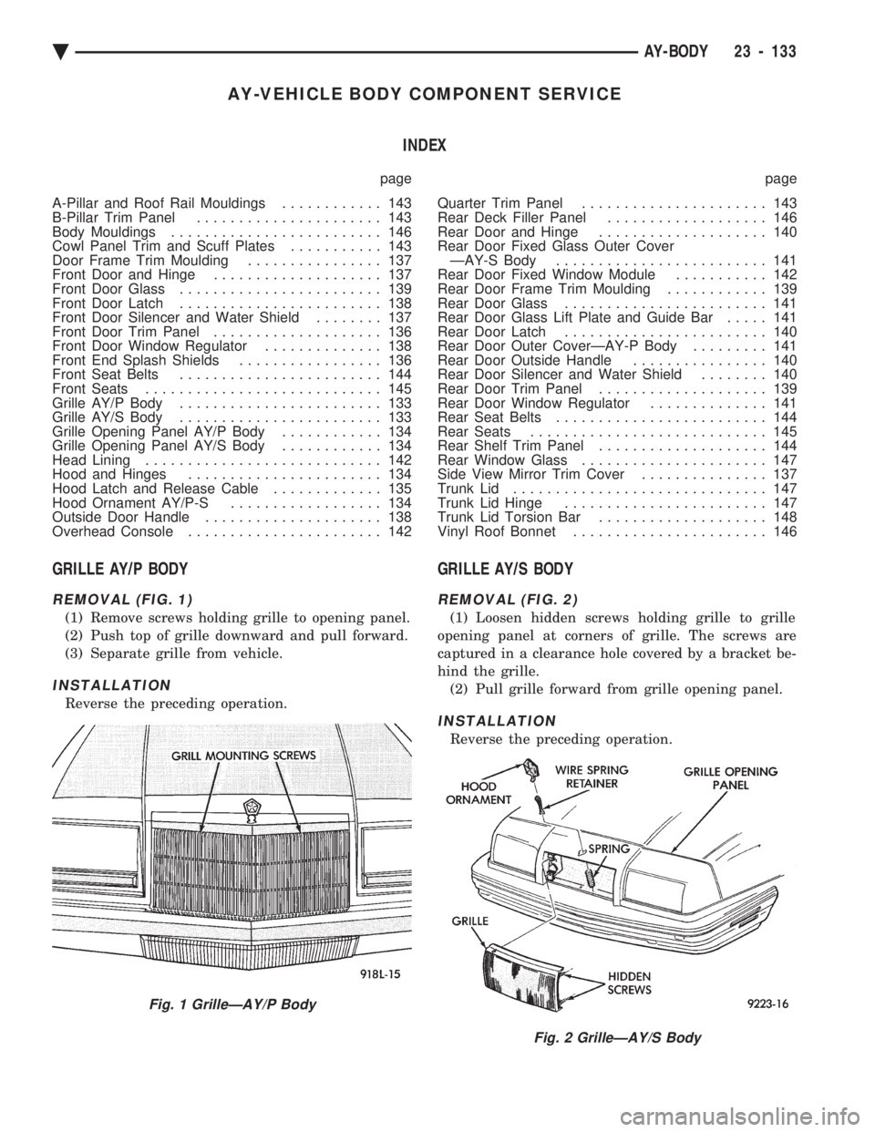
GRILLE AY/P BODY
REMOVAL (FIG. 1)
(1) Remove screws holding grille to opening panel.
(2) Push top of grille downward and pull forward.
(3) Separate grille from vehicle.
INSTALLATION
Reverse the preceding operation.
GRILLE AY/S BODY
REMOVAL (FIG. 2)
(1) Loosen hidden screws holding grille to grille
opening panel at corners of grille. The screws are
captured in a clearance hole covered by a bracket be-
hind the grille. (2) Pull grille forward from grille opening panel.
INSTALLATION
Reverse the preceding operation.
Fig. 1 GrilleÐAY/P Body
Fig. 2 GrilleÐAY/S Body
Ä AY-BODY 23 - 133