1993 CHEVROLET PLYMOUTH ACCLAIM remove seats
[x] Cancel search: remove seatsPage 168 of 2438

REAR WHEEL DRUM BRAKES INDEX
page page
Brake Drum Refacing ..................... 21
Brake Shoe Assemblies ................... 19 Description
............................. 18
Service Procedures ....................... 18
DESCRIPTION
Rear wheel drum brakes (Fig .2&3)aretwoshoe,
internal expanding type with an automatic adjuster
screw assembly that is activated each time the
brakes are applied. The automatic adjuster screw is
located directly below the wheel cylinder as shown in
figure (Fig .2&3).
WARNING: DUST AND DIRT ON BRAKE PARTS
GENERATED DURING THE NORMAL USE AND
WEAR OF MOTOR VEHICLE BRAKE SYSTEMS MAY
CONTAIN ASBESTOS FIBERS. BREATHING EXCES-
SIVE CONCENTRATIONS OF ASBESTOS FIBERS
CAN CAUSE SERIOUS BODILY HARM, SUCH AS
ASBESTOSIS AND CANCER. EXTREME CARE
SHOULD BE EXERCISED WHILE SERVICING
BRAKE ASSEMBLIES OR COMPONENTS. DO NOT CLEAN BRAKE ASSEMBLIES OR COM-
PONENTS WITH COMPRESSED AIR OR BY DRY
BRUSHING; USE A VACUUM CLEANER SPECIFI-
CALLY RECOMMENDED FOR USE WITH ASBES-
TOS FIBERS. IF A SUITABLE VACUUM CLEANER IS
NOT AVAILABLE, CLEANING SHOULD BE DONE
WET USING A WATER DAMPENED CLOTH. DO NOT CREATE DUST BY SANDING, GRINDING,
AND/OR SHAVING BRAKE LININGS OR PADS UN-
LESS SUCH OPERATION IS DONE WHILE USING
PROPERLY EXHAUST VENTILATED EQUIPMENT. DISPOSE OF ALL DUST AND DIRT SUSPECTED
TO CONTAIN ANY ASBESTOS FIBERS IN SEALED
BAGS OR CONTAINERS TO MINIMIZE DUST EXPO-
SURE TO YOURSELF AND OTHERS. FOLLOW ALL RECOMMENDED PRACTICES PRE-
SCRIBED BY THE OCCUPATIONAL SAFETY AND
HEALTH ADMINISTRATION AND THE ENVIRON-
MENTAL PROTECTION AGENCY. FOR THE HAN-
DLING, PROCESSING, AND DISPOSITION OF DUST
OR DIRT WHICH MAY CONTAIN ASBESTOS FI-
BERS. IT IS RECOMMENDED NOT TO BREATH ANY
TYPE OF BRAKE LINING MATERIAL DUST EVEN
ASBESTOS FREE, DUE TO THE FIBROUS NATURE
OF THE MATERIALS BEING USED.
SERVICE PROCEDURES
REAR BRAKE DRUM REMOVAL
If the rear brake drum is difficult to remove, fur-
ther clearance can be obtained by backing off the
brake automatic adjuster screw. Remove rubber plug
from the top of the support plate and rotate the au-
tomatic adjuster screw assembly with an upward mo-
tion, using the Brake Adjuster, Special Tool C-3784. See adjusting rear service brakes in the Service
Adjustments section in this group of the service man-
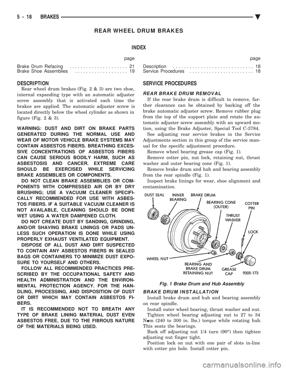
ual for the specific adjustment procedure. Remove wheel bearing grease cap (Fig. 1).
Remove cotter pin, nut lock, retaining nut, thrust
washer and outer bearing cone (Fig. 1). Remove brake drum and hub and bearing assembly
from the rear spindle (Fig. 1). Inspect brake linings for wear, shoe alignment and
contamination.
BRAKE DRUM INSTALLATION
Install brake drum and hub and bearing assembly
on rear spindle. Install outer wheel bearing, thrust washer and nut.
Tighten wheel bearing adjusting nut to 27 to 34
N Im (240 to 300 in. lbs.) torque while rotating hub.
This seats the bearings. Back off adjusting nut 1/4 turn (90É) then tighten
adjusting nut finger tight. Position lock on nut with one pair of slots in-line
with cotter pin hole. Install cotter pin.
Fig. 1 Brake Drum and Hub Assembly
5 - 18 BRAKES Ä
Page 221 of 2438

seal, a new seal should be used when reinstalling the
inner bearing. (See Fig. 1) (5) Thoroughly clean all old grease from the outer
and inner bearings, bearing cups and hub cavity (See
Fig. 1). To clean bearings, soak them in an ap-
propriate cleaning solvent. Strike the flat sur-
face of the bearing inner race against a
hardwood block several times. Immerse the
bearings in solvent between the blows to jar
grease loose and wash old particles of hardened
grease from bearings. Repeat this operation un-
til bearings are clean. Bearings can be dried
using compressed air but do not spin the bear-
ings. After cleaning, oil the bearings with engine
oil. Insert the bearing into its appropriate cup,
apply pressure to the bearing while rotating it to
test them for pitting and roughness. Replace all
worn or defective bearings. If bearing shows signs of pitting or roughness they should be
replaced. Bearings must be replaced as a set,
both the cup and the bearing need to be replaced
at the same time. If bearings are suitable for
further use, remove engine oil from bearings
using appropriate solvent and dry bearings. Re-
pack the bearings using a Multi-Purpose NLGI.
Grade 2 EP Grease such as Mopar or equivalent,
and place them in a clean covered container
until ready for installation. If a bearing packer is
not available, hand pack grease into all cavities
between bearing cage and rollers. (6) If bearings and cups are to be replaced, remove
cups from the drum or hub using a brass drift or
suitable remover. (7) Replace bearing cups with appropriate installing
tool. (8) Install inner bearing in grease coated hub and
bearing cup, and install new grease seals using the
appropriate seal installer. (9) Coat hub cavity and cup with grease.
(10) Before installing hub or drum assembly, inspect
stub axle and seal surface for burrs or roughness, and
smooth out all rough surfaces. (11) Coat the stub axle with Multi-Purpose NLGI,
Grade 2 EP grease such as Mopar or equivalent. (12) Carefully slide the hub of drum assembly onto
the stub axle. Do not drag seal or inner bearing
over the threaded area of the stub axle. (13) Install outer bearing, thrust washer and nut.
(14) Tighten the wheel bearing adjusting nut to 27 to
34 N Im (240 to 300 in. lbs.) while rotating hub or drum
assembly. This seats the bearings. (15) Back off adjusting nut 1/4 turn (90É) then
tighten adjusting nut only finger tight. (16) Position the nut lock over the bearing adjusting
nut with one pair of slots in line with the cotter pin hole
in the stub axle, and install cotter pin. (17) Install the grease caps and the wheel and tire
assemblies. Tighten wheel stud nuts to 115 N Im (85 ft.
lbs.) on all models. reinstall wheel covers if so
equipped.
Fig. 1 Rear Wheel Bearings
Ä BRAKES 5 - 71
Page 707 of 2438

POWER SEATS
CONTENTS
page page
ADJUSTER ............................. 3
CIRCUIT BREAKER TEST .................. 1
ENTHUSIAST SEAT ....................... 4
GENERAL INFORMATION .................. 1
HARNESS VOLTAGE TEST ................. 1
HORIZONTAL AND VERTICAL TRANSMISSIONS ....................... 3
MEMORY CONTROL MODULE REPLACEMENT ....................... 19
MOTOR ................................ 3
MOTOR TESTS .......................... 1
POWER MEMORY SEAT, RECLINER AND MIRRORS ............................. 5 POWER MEMORY SEAT, RECLINER AND
MIRRORS DIAGNOSIS ................... 9
POWER RECLINER MECHANISM ........... 18
POWER RECLINER MOTOR AND CABLE ..... 17
RECLINER SWITCH REPLACEMENT ......... 19
RECLINER SWITCH TEST ................. 19
SEAT ASSEMBLY ........................ 3
SWITCH REPLACEMENT REMOVAL .......... 5
SWITCH TEST ........................... 5
SWITCH TEST ........................... 3
TEST PROCEDURES ...................... 6
TEST PROCEDURES ...................... 1
GENERAL INFORMATION
Power seats can be adjusted in six different direc-
tions up, down, forward, back, tilt forward, or tilt
rearward. A three armature permanent magnet reversible mo-
tor is coupled through cables to worm gear box assem-
blies located in the seat tracks, providing the various
seat movements. The electrical circuit is protected by a 30 amp circuit
breaker located on the fuse block.
TEST PROCEDURES
Before any testing is attempted the battery should be
carefully charged and all connections and terminals
cleaned and tightened to insure proper continuity and
grounds. With dome lamp on, apply switch in direction of
failure. If dome lamp dims the seat motor is trying to
work indicating mechanical jamming. If dome lamp
does not dim, then proceed with the following electrical
tests.
CIRCUIT BREAKER TEST
Find correct circuit breaker on fuse block. Pull out
slightly but be sure that circuit breaker terminals still
contact terminals in fuse block. Connect ground wire of
voltmeter to a good ground. With probe of voltmeter
positive wire, check both terminals of circuit breaker
for battery voltage. If only one terminal checks at
battery voltage, circuit breaker is defective and must
be replaced. If neither terminal shows battery voltage,
check for open or shorted circuit to circuit breaker.
HARNESS VOLTAGE TEST
The following test will determine whether or not
voltage is continuous through the body harness to the
switch. (1) Remove power seat switch from mounting posi-
tion and disconnect switch from wiring harness. (2) Connect one lead of test light to ground terminal,
black wire (BK) of center section, and touch other test
light lead to red wire (RD) terminal. (3) If test light comes on, harness to switch is good.
If test light does not come on, perform circuit breaker
test.
MOTOR TESTS
AA BODY
(1) Remove switch from mounting position and dis-
connect from harness. (2) To check the center motor, connect a jumper wire
between pin 5 and pin 3 (Fig. 1). Connect a second
jumper wire between pin 7 and pin 4 If motor does not
operate, reverse the jumpers, pin 5 to pin 4 and pin 7 to
pin 3. If motor still does not operate check wiring
between switch connector and motor assembly. If wir-
ing checks good replace motor assembly. (3) To check the front motor, connect a jumper wire
between pin 5 and pin 1 (Fig. 1). Connect a second
jumper wire between pin 7 and pin 8. If motor does not
operate, reverse the jumpers, pin 5 to pin 8 and pin 7 to
pin 1. If motor still does not operate check wiring
between switch connector and motor assembly. If wir-
ing checks good replace motor assembly.
(4) To check the rear motor, connect a covered jumper
wire between pin 5 and pin 6 (Fig. 1). Connect a second
Ä POWER SEATS 8R - 1
Page 708 of 2438

jumper wire between pin 7 and 2.If motor does not op-
erate, reverse the jumpers, pin 5 to pin 2 and pin 7 to 6.
If motor still does not operate check wiring between
switch connector and motor assembly. If wiring checks
good replace motor assembly.
(5) If all motors and the seat operate properly, per-
form Switch Test.
AG & AJ BODIES
(1) Remove switch from mounting position and dis-
connect from harness. (2) To check the front motor, connect a jumper
wire between cavity number 2 and cavity number 9
(Fig. 2). Connect a second jumper wire between cav-
ity number 6 and cavity number 5. If the motor does
not operate, reverse the jumpers, 2 to 5 and 6 to 9. If
motor still does not operate check wiring between
switch connector and motor assembly. If wiring
checks good replace motor assembly. (3) To check the center motor, connect a jumper
wire between cavity number 2 and cavity number 8.
Connect a second jumper wire between cavity 6 and
cavity number 7. If the motor does not operate, re-
verse the jumpers, 2 to 7 and 6 to 8. If motor still
does not operate check wiring between switch con-
nector and motor assembly. If wiring checks good re-
place motor assembly. (4) To check the rear motor, connect a jumper be-
tween cavity number 2 and cavity number 10. Con-
nect a second jumper wire between cavity number 6
and cavity number 3. If the motor does not operate,
reverse the jumpers, 2 to 3 and 6 to 10. If motor still
does not operate, check wiring between switch con-
nector and motor assembly. If wiring checks good re-
place motor assembly. (5) To check the seat back recliner motor if
equipped, connect a jumper wire be tween cavity
number 2 and cavity number 1. Connect a second
jumper wire between cavity number 6 and cavity
number 11. If the motor does not operate, reverse the jumpers (2 to 11 and 6 to 1). If motor still does not
operate check wiring be tween switch connector and
motor assembly. If wiring checks good replace motor
assembly.
(6) If all motors and the seat operate properly, per-
form Switch Test.
AC AND AY BODIES
The following tests do not apply to left seat on ve-
hicles equipped with memory mirrors/seats. Refer to
test procedures for power memory mirrors/seats in
this section. (1) Remove switch from mounting position and dis-
connect from harness. (2) To check the front motor, connect a jumper
wire between cavity number 3 and cavity number 8
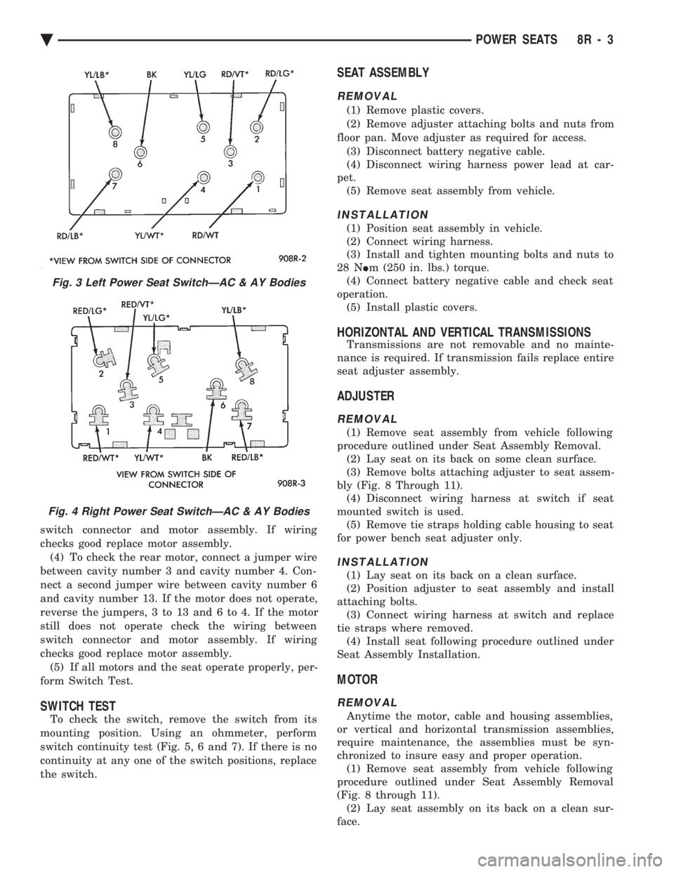
(Fig. 3 and 4). Connect a second jumper wire between
cavity number 6 and cavity number 7. If the motor
does not operate, reverse the jumpers, 3 to 7 and 6 to
8. If the motor still does not operate check the wiring
between switch connector and motor assembly. If
wiring checks good replace motor assembly. (3) To check the center motor, connect a jumper
wire between cavity number 3 and cavity number 5.
Connect a second jumper wire between cavity num-
ber 6 and cavity number 2. If the motor does not op-
erate, reverse the jumpers, 3 to 2 and 6 to 5. If the
motor still does not operate check the wiring between
Fig. 1 Power Seat Switch ConnectorÐAA Body
Fig. 2 Power Seat Switch ConnectorÐAG & AJ Bodies
8R - 2 POWER SEATS Ä
Page 709 of 2438

switch connector and motor assembly. If wiring
checks good replace motor assembly.(4) To check the rear motor, connect a jumper wire
between cavity number 3 and cavity number 4. Con-
nect a second jumper wire between cavity number 6
and cavity number 13. If the motor does not operate,
reverse the jumpers, 3 to 13 and 6 to 4. If the motor
still does not operate check the wiring between
switch connector and motor assembly. If wiring
checks good replace motor assembly. (5) If all motors and the seat operate properly, per-
form Switch Test.
SWITCH TEST
To check the switch, remove the switch from its
mounting position. Using an ohmmeter, perform
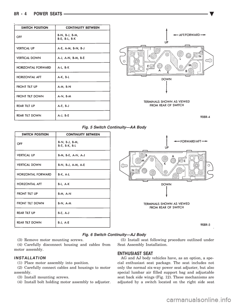
switch continuity test (Fig. 5, 6 and 7). If there is no
continuity at any one of the switch positions, replace
the switch.
SEAT ASSEMBLY
REMOVAL
(1) Remove plastic covers.
(2) Remove adjuster attaching bolts and nuts from
floor pan. Move adjuster as required for access. (3) Disconnect battery negative cable.
(4) Disconnect wiring harness power lead at car-
pet. (5) Remove seat assembly from vehicle.
INSTALLATION
(1) Position seat assembly in vehicle.
(2) Connect wiring harness.
(3) Install and tighten mounting bolts and nuts to
28 N Im (250 in. lbs.) torque.
(4) Connect battery negative cable and check seat
operation. (5) Install plastic covers.
HORIZONTAL AND VERTICAL TRANSMISSIONS
Transmissions are not removable and no mainte-
nance is required. If transmission fails replace entire
seat adjuster assembly.
ADJUSTER
REMOVAL
(1) Remove seat assembly from vehicle following
procedure outlined under Seat Assembly Removal. (2) Lay seat on its back on some clean surface.
(3) Remove bolts attaching adjuster to seat assem-
bly (Fig. 8 Through 11). (4) Disconnect wiring harness at switch if seat
mounted switch is used. (5) Remove tie straps holding cable housing to seat
for power bench seat adjuster only.
INSTALLATION
(1) Lay seat on its back on a clean surface.
(2) Position adjuster to seat assembly and install
attaching bolts. (3) Connect wiring harness at switch and replace
tie straps where removed. (4) Install seat following procedure outlined under
Seat Assembly Installation.
MOTOR
REMOVAL
Anytime the motor, cable and housing assemblies,
or vertical and horizontal transmission assemblies,
require maintenance, the assemblies must be syn-
chronized to insure easy and proper operation. (1) Remove seat assembly from vehicle following
procedure outlined under Seat Assembly Removal
(Fig. 8 through 11). (2) Lay seat assembly on its back on a clean sur-
face.
Fig. 3 Left Power Seat SwitchÐAC & AY Bodies
Fig. 4 Right Power Seat SwitchÐAC & AY Bodies
Ä POWER SEATS 8R - 3
Page 710 of 2438

(3) Remove motor mounting screws.
(4) Carefully disconnect housing and cables from
motor assembly.
INSTALLATION
(1) Place motor assembly into position.
(2) Carefully connect cables and housings to motor
assembly. (3) Install mounting screws.
(4) Install bolt holding motor assembly to adjuster. (5) Install seat following procedure outlined under
Seat Assembly Installation.
ENTHUSIAST SEAT
AG and AJ body vehicles have, as an option, a spe-
cial enthusiast seat package. The seat includes not
only the normal six-way power seat adjuster, but also
special lumbar air filled support bag and adjustable
seat back side wings (Fig. 12). These mechanisms are
adjusted by a switch located on the right side seat
Fig. 5 Switch ContinuityÐAA Body
Fig. 6 Switch ContinuityÐAJ Body
8R - 4 POWER SEATS Ä
Page 711 of 2438

wing. Refer to Owner Manual supplied with vehicle
for complete instructions for seat operation.
SWITCH TEST
For switch testing, remove switch from its mount-
ing location. Using an ohmmeter, refer to Figures 13
and 14 to determine if continuity is correct. If these
results are not obtained, replace the switch.
SWITCH REPLACEMENT REMOVAL
(1) Remove left cushion side shield.
(2) Disconnect wiring from switch.
(3) Depress bezel retainers and push switch from
bezel. (4) For installation, reverse above procedure.
POWER MEMORY SEAT, RECLINER AND
MIRRORS
AC & AY Body vehicles have, as an option, a spe-
cial 2 position memory power seat, recliner and
memory power outside rear view mirror system.
Each of the components can be moved to a desired
position by operating switches (Fig. 15). The seat and
recliner use potentiometers as position sensors and
the mirrors use rheostats to send their positioning
information back to the control module in the driv-
er's seat. After the desired seat and mirror position is
set. The seat, recliner, and mirror position can be
memorized at any time by pressing and release the
Set button. Followed by pressing the Position 1 or 2
button, for the specific position desired. DO NOT
press any other seat related switch for at least 5 sec-
onds. However, for the driver to recall a position, the
vehicle must not be moving and the seat belt must
NOT be buckled. Refer to the Owners Manual sup-
plied with the vehicle for complete instructions on
system operation.
Fig. 7 Switch ContinuityÐAG & AJ Bodies (8-Way)
Fig. 8 Seat AdjusterÐAC and AJ Bodies
Ä POWER SEATS 8R - 5
Page 716 of 2438

(7) If battery is good, check for continuity of driv-
er's power seat switch. Refer to Power Memory Seat
Switch Continuity (Fig. 16). (8) Check that all connectors are securely plugged
into control module under driver's seat with no ter-
minal push outs. (9) No correctable faults are found in the above
steps. The battery voltage and ground circuits are
good into the control module. There is battery volt-
age through the seat switch to the control module.
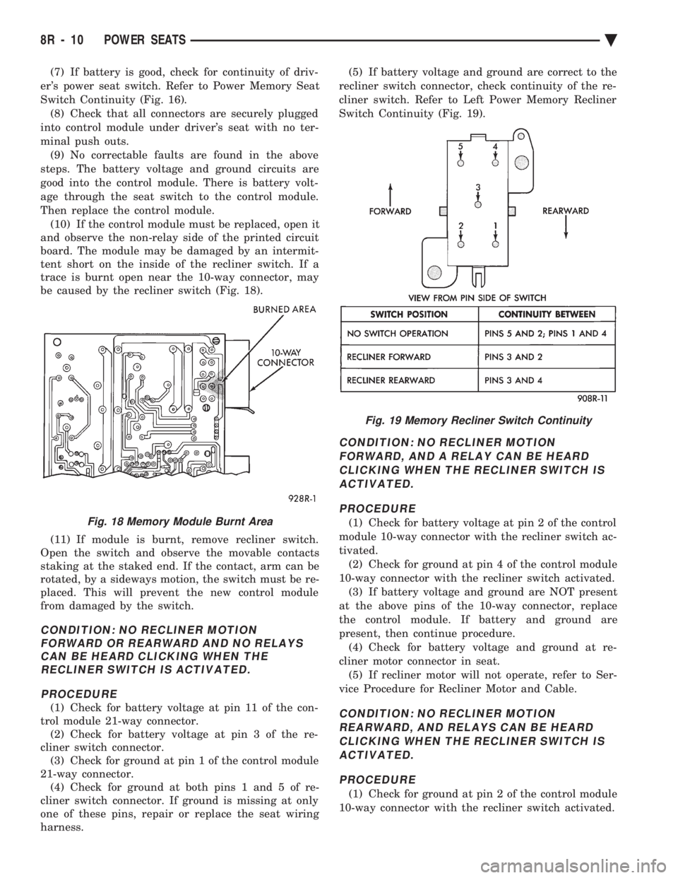
Then replace the control module. (10) If the control module must be replaced, open it
and observe the non-relay side of the printed circuit
board. The module may be damaged by an intermit-
tent short on the inside of the recliner switch. If a
trace is burnt open near the 10-way connector, may
be caused by the recliner switch (Fig. 18).
(11) If module is burnt, remove recliner switch.
Open the switch and observe the movable contacts
staking at the staked end. If the contact, arm can be
rotated, by a sideways motion, the switch must be re-
placed. This will prevent the new control module
from damaged by the switch.
CONDITION: NO RECLINER MOTION FORWARD OR REARWARD AND NO RELAYSCAN BE HEARD CLICKING WHEN THERECLINER SWITCH IS ACTIVATED.
PROCEDURE
(1) Check for battery voltage at pin 11 of the con-
trol module 21-way connector. (2) Check for battery voltage at pin 3 of the re-
cliner switch connector. (3) Check for ground at pin 1 of the control module
21-way connector. (4) Check for ground at both pins 1 and 5 of re-
cliner switch connector. If ground is missing at only
one of these pins, repair or replace the seat wiring
harness. (5) If battery voltage and ground are correct to the
recliner switch connector, check continuity of the re-
cliner switch. Refer to Left Power Memory Recliner
Switch Continuity (Fig. 19).
CONDITION: NO RECLINER MOTION FORWARD, AND A RELAY CAN BE HEARDCLICKING WHEN THE RECLINER SWITCH ISACTIVATED.
PROCEDURE
(1) Check for battery voltage at pin 2 of the control
module 10-way connector with the recliner switch ac-
tivated. (2) Check for ground at pin 4 of the control module
10-way connector with the recliner switch activated. (3) If battery voltage and ground are NOT present
at the above pins of the 10-way connector, replace
the control module. If battery and ground are
present, then continue procedure. (4) Check for battery voltage and ground at re-
cliner motor connector in seat. (5) If recliner motor will not operate, refer to Ser-
vice Procedure for Recliner Motor and Cable.
CONDITION: NO RECLINER MOTION REARWARD, AND RELAYS CAN BE HEARDCLICKING WHEN THE RECLINER SWITCH ISACTIVATED.
PROCEDURE
(1) Check for ground at pin 2 of the control module
10-way connector with the recliner switch activated.
Fig. 18 Memory Module Burnt Area
Fig. 19 Memory Recliner Switch Continuity
8R - 10 POWER SEATS Ä