1993 CHEVROLET PLYMOUTH ACCLAIM remove seats
[x] Cancel search: remove seatsPage 719 of 2438
ity 9 and pin 7 of the control module 25-way connec-
tor. The vehicle speed sensor signal can be tested
with a volt/ohmmeter at pin 7 of the control module
25-way connector. Turn on the vehicle ignition and
check fo r a 5 volt signal as the vehicle is moved
about 3 to 5 feet. If not repair open wiring, terminal
push out, bad crimp, drive in vehicle speed sensor,
etc., as necessary to correct condition. Ensure that
the 25-way connector is plugged into the control
module securely. Road test vehicle after repairs have
been made to ensure that no recalls can occur while
moving.
CONDITION: INSTRUMENT CLUSTER SPEEDOMETER STAYS AT 0 MPH/ (0 KM/H)WHILE VEHICLE IS MOVING, BODYCOMPUTER DOES NOT LOCK DOORS AT 15MPH (24 KM/H), AND THE SPEED CONTROLWILL NOT ACCEPT A SPEED SET.
PROCEDURE
(1) Remove driver's seat anchor bolts and nuts. Ad-
just the driver's seat to a safe driving position. Dis-
connect the 25-way connector from the memory seat
control module. Replace the driver's seat anchor bolts
and nuts. Road test the vehicle to complete this diag-
nosis. If the doors lock, the cruise control accepts a
set, and the speedometer now works, replace the
Memory Seat control module. (2) After replacing the Memory Seat control mod-
ule, perform the memory seat diagnostic self tests.
This teaches the new module it's soft limits and now
re-road test the vehicle before returning it to the cus-
tomer.
CONDITION: NO SEAT MOVEMENT IN THE RECALL MODE, SEAT WILL MOVE BYMANUAL SWITCH ACTUATION IN ALLDIRECTIONS WITHOUT STALL DETECTION.
PROCEDURE
(1) Check for 5 volts at pin 10 of the control mod-
ule 25-way connector. This is the 5 volt feed from the
control module to the seat track position sensing po-
tentiometer. (2) Check for ground at pin 8 of the control module
25-way connector. To test for ground, one lead of the
voltmeter must be connected to either the 5 volt sup-
ply for the control module or the battery positive. If
the sense voltage and ground are NOT present at the
above pins of the 21-way control module connector.
When the seat switch is pressed, replace the control
module. An inadvertent application of battery volt-
age to the circuit could damaged the control module.
If the voltage and ground circuits are present then
continue this procedure. (3) Check for 5 volts at pin 5 of the natural 5-way
connector plugged into the power seat adjuster mo-
tors end-bell. (4) Check for ground at pin 4 of the natural 5-way
connector plugged into the power seat adjuster mo-
tors end-bell. If the power seat adjuster still has no
movement in the recall mode, then continue this pro-
cedure. (5) Disconnect the natural 5-way connector from
the power seat adjuster motors end-bell. (6) Check with an ohmmeter for a resistance read-
ing that may be from 2600 to 4000 ohms between
pins 4 and 5 of the motors end-bell connector. If
there is an open circuit reading or the reading ob-
tained falls outside this range, then replace the seat
motor package assembly. After replacement of the
seat motor package, reconnect all wiring connectors
and reinstall seat assembly in vehicle. Operate the
switches manually to cause maximum seat move-
ment in all directions. Perform the memory seat di-
agnostic self check so the control module will learn
the new soft limits of the assembly.
CONDITION: NO SEAT TRACK FORWARD OR REARWARD MOVEMENT IN THE RECALLMODE, SEAT TRACK WILL MOVE FORWARDOR REARWARD BY MANUAL SWITCHACTUATION WITHOUT STALL DETECTION.
PROCEDURE
(1) Check for a voltage at pin 12 of the control
module 21-way connector. Less than 5 volts for the
seat track fully forward and more than 0 volts when
fully rearward. This voltage should vary correspond-
ing to the position. (2) Check for a voltage at pin 1 of the natural
5-way connector, Same as in step (1) above. The
ground lead connected to pin 4 of the 5-way connec-
tor. If the voltage reading is at 0 volts, disconnect
the 5-way natural connector and check for a short to
ground in the harness. If no short is found, reconnect
the connector and continue the procedure. (3) Check for the voltage to vary as noted above, if
it does not vary as the seat track is moved forward
and rearward, the sensing potentiometer is defective.
Replace the seat motor package assembly. After re-
placement of the seat motor package, reconnect all
wiring connectors and reinstall seat assembly in ve-
hicle. Operate the switches manually to cause maxi-
mum seat movement in all directions. Perform the
memory seat diagnostic self check so the control
module will learn the new soft limits of the assem-
bly.
Ä POWER SEATS 8R - 13
Page 723 of 2438
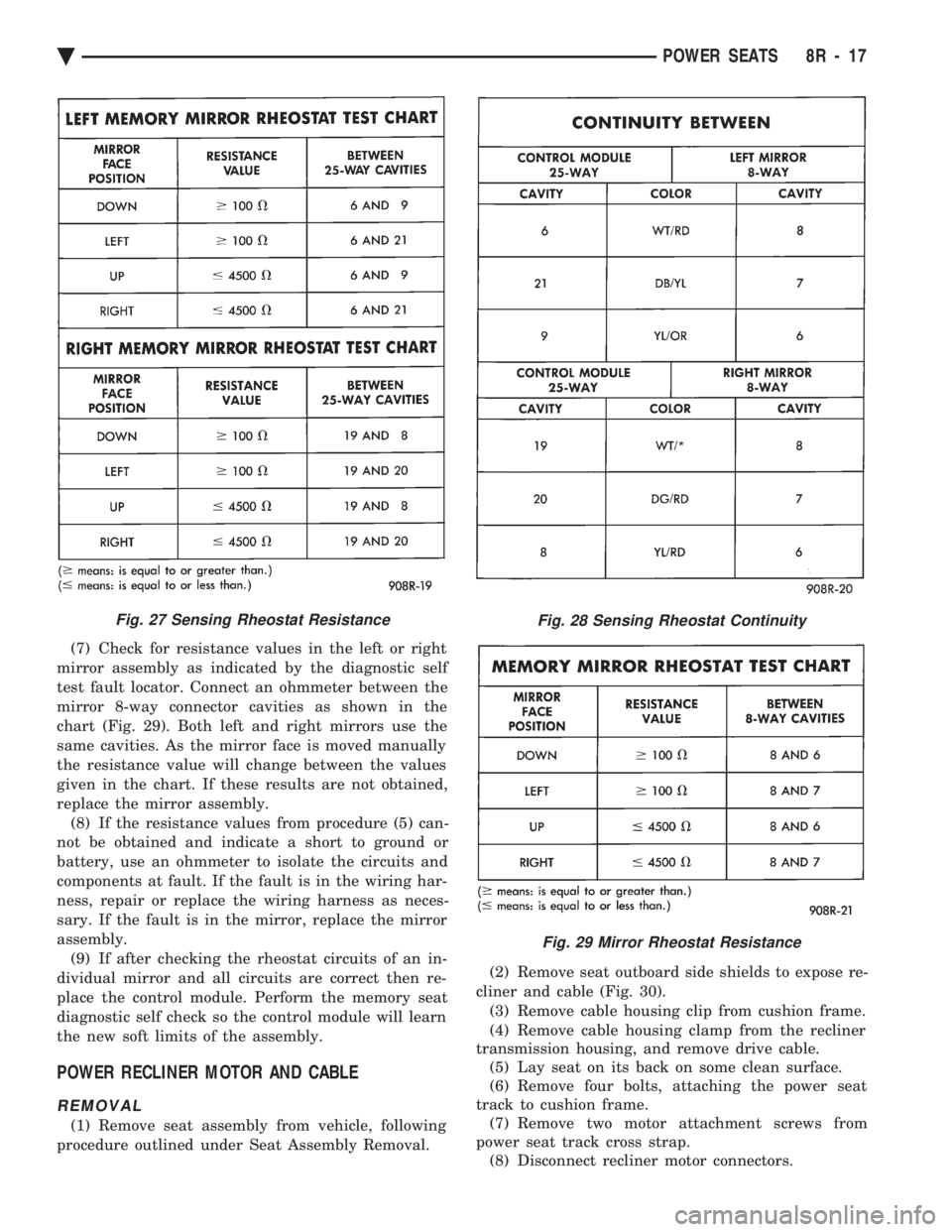
(7) Check for resistance values in the left or right
mirror assembly as indicated by the diagnostic self
test fault locator. Connect an ohmmeter between the
mirror 8-way connector cavities as shown in the
chart (Fig. 29). Both left and right mirrors use the
same cavities. As the mirror face is moved manually
the resistance value will change between the values
given in the chart. If these results are not obtained,
replace the mirror assembly. (8) If the resistance values from procedure (5) can-
not be obtained and indicate a short to ground or
battery, use an ohmmeter to isolate the circuits and
components at fault. If the fault is in the wiring har-
ness, repair or replace the wiring harness as neces-
sary. If the fault is in the mirror, replace the mirror
assembly. (9) If after checking the rheostat circuits of an in-
dividual mirror and all circuits are correct then re-
place the control module. Perform the memory seat
diagnostic self check so the control module will learn
the new soft limits of the assembly.
POWER RECLINER MOTOR AND CABLE
REMOVAL
(1) Remove seat assembly from vehicle, following
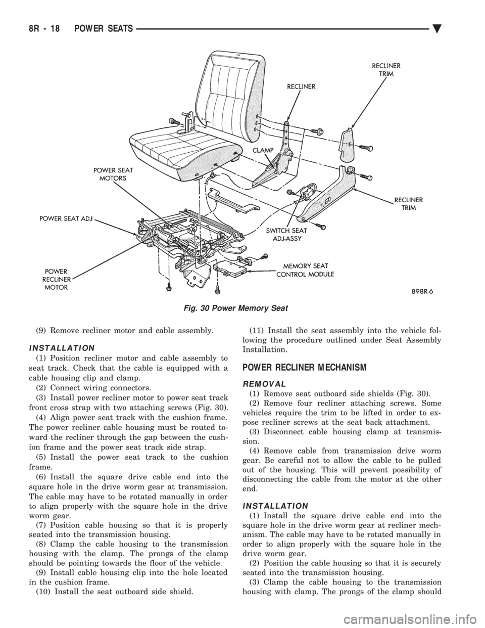
procedure outlined under Seat Assembly Removal. (2) Remove seat outboard side shields to expose re-
cliner and cable (Fig. 30). (3) Remove cable housing clip from cushion frame.
(4) Remove cable housing clamp from the recliner
transmission housing, and remove drive cable. (5) Lay seat on its back on some clean surface.
(6) Remove four bolts, attaching the power seat
track to cushion frame. (7) Remove two motor attachment screws from
power seat track cross strap. (8) Disconnect recliner motor connectors.
Fig. 27 Sensing Rheostat ResistanceFig. 28 Sensing Rheostat Continuity
Fig. 29 Mirror Rheostat Resistance
Ä POWER SEATS 8R - 17
Page 724 of 2438
(9) Remove recliner motor and cable assembly.
INSTALLATION
(1) Position recliner motor and cable assembly to
seat track. Check that the cable is equipped with a
cable housing clip and clamp. (2) Connect wiring connectors.
(3) Install power recliner motor to power seat track
front cross strap with two attaching screws (Fig. 30). (4) Align power seat track with the cushion frame.
The power recliner cable housing must be routed to-
ward the recliner through the gap between the cush-
ion frame and the power seat track side strap. (5) Install the power seat track to the cushion
frame. (6) Install the square drive cable end into the
square hole in the drive worm gear at transmission.
The cable may have to be rotated manually in order
to align properly with the square hole in the drive
worm gear. (7) Position cable housing so that it is properly
seated into the transmission housing. (8) Clamp the cable housing to the transmission
housing with the clamp. The prongs of the clamp
should be pointing towards the floor of the vehicle. (9) Install cable housing clip into the hole located
in the cushion frame. (10) Install the seat outboard side shield. (11) Install the seat assembly into the vehicle fol-
lowing the procedure outlined under Seat Assembly
Installation.
POWER RECLINER MECHANISM
REMOVAL
(1) Remove seat outboard side shields (Fig. 30).
(2) Remove four recliner attaching screws. Some
vehicles require the trim to be lifted in order to ex-
pose recliner screws at the seat back attachment. (3) Disconnect cable housing clamp at transmis-
sion. (4) Remove cable from transmission drive worm
gear. Be careful not to allow the cable to be pulled
out of the housing. This will prevent possibility of
disconnecting the cable from the motor at the other
end.
INSTALLATION
(1) Install the square drive cable end into the
square hole in the drive worm gear at recliner mech-
anism. The cable may have to be rotated manually in
order to align properly with the square hole in the
drive worm gear. (2) Position the cable housing so that it is securely
seated into the transmission housing. (3) Clamp the cable housing to the transmission
housing with clamp. The prongs of the clamp should
Fig. 30 Power Memory Seat
8R - 18 POWER SEATS Ä
Page 725 of 2438
be pointing towards the floor of the vehicle. (4) Install the four recliner to seat frame fasteners
(Fig. 30). (5) Install seat outboard side shields and fix all
trim so that no foam is exposed. (6) Set system soft limits.
MEMORY CONTROL MODULE REPLACEMENT
(1) Remove seat assembly from vehicle and follow the
procedure outlined under Seat Assembly Removal.
(2) Lay seat on its back on a clean surface.
(3) Remove screws attaching control module to
seat track (Fig. 30). (4) Disconnect control module wiring.
(5) Remove control module.
(6) For installation reverse above procedures. Set
system soft limits by performing the memory seat di-
agnostic self check. So that the control module will
learn the soft limits of the assembly.
RECLINER SWITCH REPLACEMENT
(1) Remove seat side shields (Fig. 30).
(2) Disconnect wiring from switch.
(3) Remove attaching screws from side shields.
(4) Remove switch.
(5) For installation reverse above procedures.
RECLINER SWITCH TEST
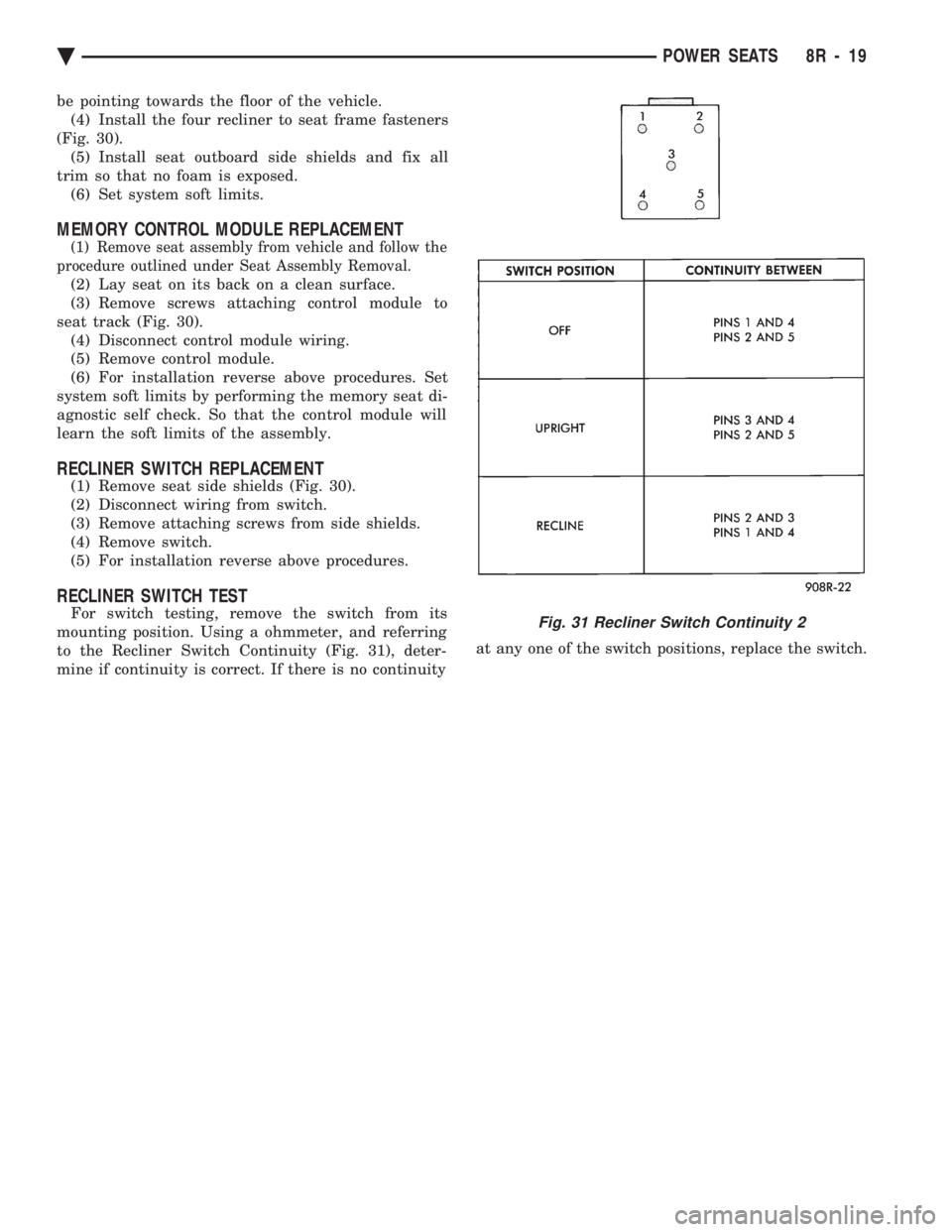
For switch testing, remove the switch from its
mounting position. Using a ohmmeter, and referring
to the Recliner Switch Continuity (Fig. 31), deter-
mine if continuity is correct. If there is no continuity at any one of the switch positions, replace the switch.Fig. 31 Recliner Switch Continuity 2
Ä
POWER SEATS 8R - 19
Page 1594 of 2438
springs using Tool C-3422-B. (2) Remove valve retaining locks, valve spring re-
tainers, valve stem seals and valve springs. (3) Before removing valves, remove any burrs
from valve stem lock grooves to prevent damage
to the valve guides. Identify valves to insure instal-
lation in original location.
VALVE INSPECTION (1) Clean valves thoroughly and discard burned,
warped and cracked valves. (2) Measure valve stems for wear.
(3) If valve stems are worn more than 0.05 mm (.002
inch.) replace valve.
VALVE GUIDES
(1) Remove carbon and varnish deposits from inside
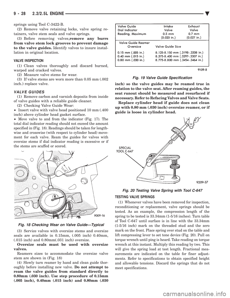
of valve guides with a reliable guide cleaner. (2) Checking Valve Guide Wear:
² Insert valve with valve head positioned 10 mm (.400
inch) above cylinder head gasket surface.
²
Move valve to and from the indicator (Fig. 17). The
total dial indicator reading should not exceed the amount
specified in (Fig. 18). Readings should be taken for length-
wise and crosswise (with respect to cylinder head) move-
ment for each valve. Ream the guides for valves with
oversize stems if dial indicator reading is excessive or if
the stems are scuffed or scored.
(3) Service valves with oversize stems and oversize
seals are available in 0.15mm, (.005 inch) 0.40mm,
(.015 inch) and 0.80mm(.031 inch) oversize. Oversize seals must be used with oversize
valves. Reamers sizes to accommodate the oversize valve
stem are shown in (Fig. 18)
(4) Slowly turn reamer by hand and clean guide thor-
oughly before installing new valve. Do not attempt to
ream the valve guides from standard directly to
0.80mm (.030 inch). Use step procedure of 0.15mm
(.005 inch), 0.40mm (.015 inch) and 0.80mm (.030 inch) so the valve guides may be reamed true in
relation to the valve seat. After reaming guides, the
seat runout should be measured and resurfaced if
necessary. Refer to Refacing Valves and Valve Seats.
Replace cylinder head if guide does not clean
up with 0.80 mm (.030 inch) oversize reamer, or if
guide is loose in cylinder head.
TESTING VALVE SPRINGS
(1) Whenever valves have been removed for inspection,
reconditioning or replacement, valve springs should be
tested. As an example, the compression length of the
spring to be tested is 33.34mm (1-5/16 inches). Turn table
of Tool C-647 until surface is in line with the 33.34mm
(1-5/16 inch) mark on the threaded stud and the zero
mark on the front. Place spring over stud on the table and
lift compressing lever to set tone device (Fig. 20). Pull on
torque wrench until ping is heard. Take reading on torque
wrench at this instant. Multiply this reading by two. This
will give the spring load at test length. Fractional mea-
surements are indicated on the table for finer adjust-
ments. Refer to specifications to obtain specified height
and allowable tensions. Discard the springs that do not
meet specifications.
Fig. 18 Checking Wear on Valve GuideÐTypical
Fig. 19 Valve Guide Specification
Fig. 20 Testing Valve Spring with Tool C-647
9 - 28 2.2/2.5L ENGINE Ä
Page 1671 of 2438
(3) Before removing valves, remove any burrs
from valve stem lock grooves to prevent damage
to the valve guides. Identify valves to insure instal-
lation in original location.
VALVE INSPECTION
(1) Clean valves thoroughly and discard burned,
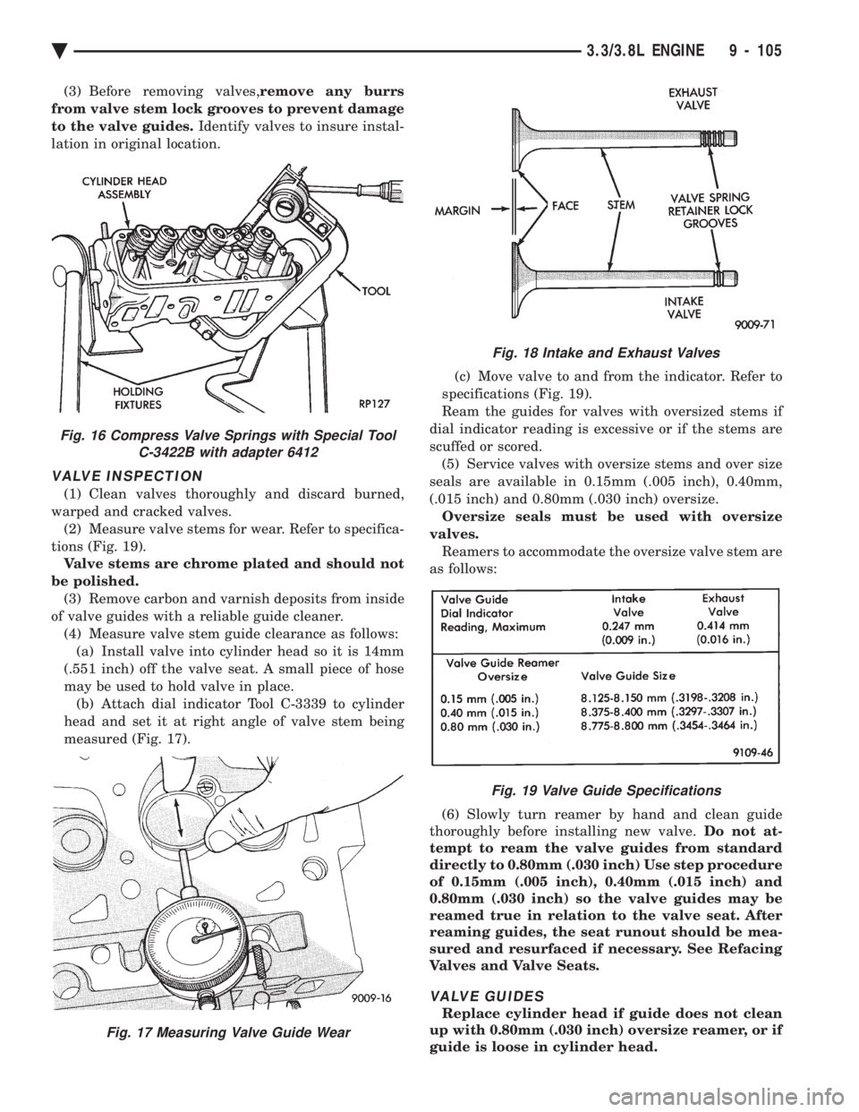
warped and cracked valves. (2) Measure valve stems for wear. Refer to specifica-
tions (Fig. 19). Valve stems are chrome plated and should not
be polished. (3) Remove carbon and varnish deposits from inside
of valve guides with a reliable guide cleaner. (4) Measure valve stem guide clearance as follows:(a) Install valve into cylinder head so it is 14mm
(.551 inch) off the valve seat. A small piece of hose
may be used to hold valve in place. (b) Attach dial indicator Tool C-3339 to cylinder
head and set it at right angle of valve stem being
measured (Fig. 17). (c) Move valve to and from the indicator. Refer to
specifications (Fig. 19).
Ream the guides for valves with oversized stems if
dial indicator reading is excessive or if the stems are
scuffed or scored. (5) Service valves with oversize stems and over size
seals are available in 0.15mm (.005 inch), 0.40mm,
(.015 inch) and 0.80mm (.030 inch) oversize. Oversize seals must be used with oversize
valves. Reamers to accommodate the oversize valve stem are
as follows:
(6) Slowly turn reamer by hand and clean guide
thoroughly before installing new valve. Do not at-
tempt to ream the valve guides from standard
directly to 0.80mm (.030 inch) Use step procedure
of 0.15mm (.005 inch), 0.40mm (.015 inch) and
0.80mm (.030 inch) so the valve guides may be
reamed true in relation to the valve seat. After
reaming guides, the seat runout should be mea-
sured and resurfaced if necessary. See Refacing
Valves and Valve Seats.
VALVE GUIDES
Replace cylinder head if guide does not clean
up with 0.80mm (.030 inch) oversize reamer, or if
guide is loose in cylinder head.
Fig. 18 Intake and Exhaust Valves
Fig. 19 Valve Guide Specifications
Fig. 16 Compress Valve Springs with Special Tool C-3422B with adapter 6412
Fig. 17 Measuring Valve Guide Wear
Ä 3.3/3.8L ENGINE 9 - 105
Page 1672 of 2438
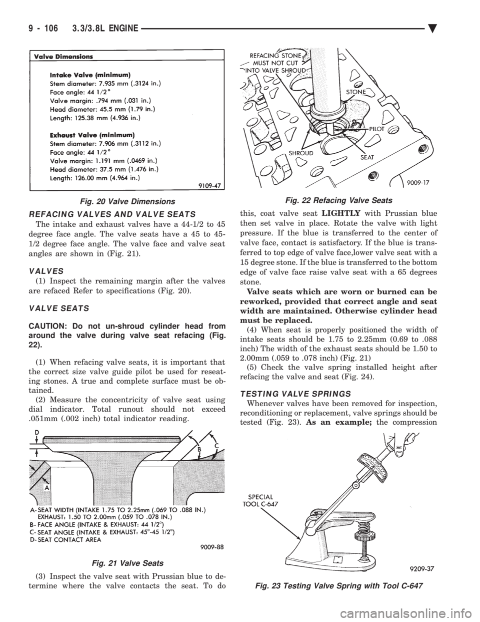
REFACING VALVES AND VALVE SEATS
The intake and exhaust valves have a 44-1/2 to 45
degree face angle. The valve seats have a 45 to 45-
1/2 degree face angle. The valve face and valve seat
angles are shown in (Fig. 21).
VALVES
(1) Inspect the remaining margin after the valves
are refaced Refer to specifications (Fig. 20).
VALVE SEATS
CAUTION: Do not un-shroud cylinder head from
around the valve during valve seat refacing (Fig.
22).
(1) When refacing valve seats, it is important that
the correct size valve guide pilot be used for reseat-
ing stones. A true and complete surface must be ob-
tained. (2) Measure the concentricity of valve seat using
dial indicator. Total runout should not exceed
.051mm (.002 inch) total indicator reading.
(3) Inspect the valve seat with Prussian blue to de-
termine where the valve contacts the seat. To do this, coat valve seat
LIGHTLYwith Prussian blue
then set valve in place. Rotate the valve with light
pressure. If the blue is transferred to the center of
valve face, contact is satisfactory. If the blue is trans-
ferred to top edge of valve face,lower valve seat with a
15 degree stone. If the blue is transferred to the bottom
edge of valve face raise valve seat with a 65 degrees
stone. Valve seats which are worn or burned can be
reworked, provided that correct angle and seat
width are maintained. Otherwise cylinder head
must be replaced. (4) When seat is properly positioned the width of
intake seats should be 1.75 to 2.25mm (0.69 to .088
inch) The width of the exhaust seats should be 1.50 to
2.00mm (.059 to .078 inch) (Fig. 21) (5) Check the valve spring installed height after
refacing the valve and seat (Fig. 24).
TESTING VALVE SPRINGS
Whenever valves have been removed for inspection,
reconditioning or replacement, valve springs should be
tested (Fig. 23). As an example; the compression
Fig. 23 Testing Valve Spring with Tool C-647
Fig. 20 Valve Dimensions
Fig. 21 Valve Seats
Fig. 22 Refacing Valve Seats
9 - 106 3.3/3.8L ENGINE Ä
Page 1673 of 2438
length of the spring to be tested is 33.34mm (1-5/16
inches). Turn table of Tool C-647 until surface is in line
with the 33.34mm (1-5/16 inch) mark on the threaded
stud and the zero mark on the front. Place spring over
stud on the table and lift compressing lever to set tone
device. Pull on torque wrench until ping is heard. Take
reading on torque wrench at this instant. Multiply this
reading by two. This will give the spring load at test
length. Fractional measurements are indicated on the
table for finer adjustments. Refer to specifications to
obtain specified height and allowable tensions. Discard
the springs that do not meet specifications.
VALVE INSTALLATION
(1) Coat valve stems with clean engine oil and insert
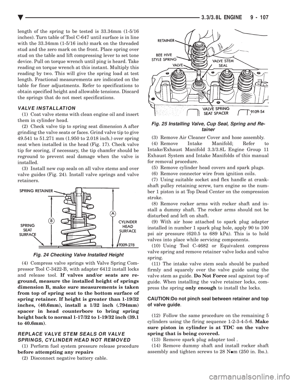
them in cylinder head. (2) Check valve tip to spring seat dimension A after
grinding the valve seats or faces. Grind valve tip to give
49.541 to 51.271 mm (1.950 to 2.018 inch.) over spring
seat when installed in the head (Fig. 17). Check valve
tip for scoring, if necessary, the tip chamfer should be
reground to prevent seal damage when the valve is
installed. (3) Install new cup seals on all valve stems and over
valve guides (Fig. 24). Install valve springs and valve
retainers.
(4) Compress valve springs with Valve Spring Com-
pressor Tool C-3422-B, with adapter 6412 install locks
and release tool. If valves and/or seats are re-
ground, measure the installed height of springs
dimension B, make sure measurements is taken
from top of spring seat to the bottom surface of
spring retainer. If height is greater than 1-19/32
inches, (40.6mm), install a 1/32 inch (.794mm)
spacer in head counterbore to bring spring
height back to normal 1-17/32 to 1-19/32 inch (39.1
to 40.6mm) .
REPLACE VALVE STEM SEALS OR VALVE
SPRINGS, CYLINDER HEAD NOT REMOVED
(1) Perform fuel system pressure release procedure
before attempting any repairs (2) Disconnect negative battery cable. (3) Remove Air Cleaner Cover and hose assembly.
(4) Remove Intake Manifold; Refer to
Intake/Exhaust Manifold 3.3/3.8L Engine Group 11
Exhaust System and Intake Manifolds of this manual
for removal procedure. (5) Remove cylinder head covers and spark plugs.
(6) Remove connector wire from ignition coils.
(7) Using suitable socket and flex handle at crank-
shaft pulley retaining screw, turn engine so the num-
ber 1 piston is at Top Dead Center on the compression
stroke. (8) Remove rocker arms with rocker shaft and in-
stall a dummy shaft. The rocker arms should not be
disturbed and left on shaft. (9) With air hose attached to spark plug adapter
installed in number 1 spark plug hole, apply 90 to 100
psi air pressure (620.5 to 689 kPa). This is to hold
valves into place while servicing components. (10) Using Tool C-4682 or Equivalent compress
valve spring and remove retainer valve locks and valve
spring. (11) The intake valve stem seals should be pushed
firmly and squarely over the valve guide using the
valve stem as guide. Do Not Forceseal against top of
guide. When installing the valve retainer locks, com-
press the spring only enoughto install the locks.
CAUTION:Do not pinch seal between retainer and top
of valve guide .
(12) Follow the same procedure on the remaining 5
cylinders using the firing sequence 1-2-3-4-5-6. Make
sure piston in cylinder is at TDC on the valve
spring that is being covered. (13) Remove spark plug adapter tool .
(14) Remove dummy shaft and install rocker shaft
assembly and tighten screws to 28 N Im (250 in. lbs.).
Fig. 24 Checking Valve Installed Height
Fig. 25 Installing Valve, Cup Seal, Spring and Re-
tainer
Ä 3.3/3.8L ENGINE 9 - 107