1993 CHEVROLET PLYMOUTH ACCLAIM reset
[x] Cancel search: resetPage 2064 of 2438

(7) Press the number 5 on the DRB II scan tool
key pad (Adjustments). (8) Press the number 3 on the DRB II scan tool
key pad (Quick Learn). Then follow the instructions
on the DRB II scan tool screen.
PINION FACTOR PROCEDURE
The vehicle speed readings for the speedometer are
taken from the output speed sensor. Because of dif-
ferent tire sizes and final drive ratios, the transmis-
sion control module must be calibrated to reflect the
different combinations of equipment. A procedure has
been developed called Pinion Factor. It allows the
technician to set the transmission control module ini-
tial setting so that the speedometer readings will be
correct. Failure to perform this procedure will cause a ``No
Speedometer Operation'' condition. This procedure must be performed if the transmis-
sion control module has been replaced. To properly read or reset the Pinion Factor, it is
necessary to use a DRB II scan tool. Perform the fol-
lowing steps with the DRB II scan tool to read or re-
set the Pinion Factor: (1) Plug the DRB II scan tool into the blue CCD
Bus connector. The connector is located under the in-
strument panel on the drivers side of the vehicle. (2) Insert the 1993 DRB II scan tool cartridge into
the DRB II scan tool. (3) The red and green lights on the DRB II scan
tool will light up and then begin flashing. Wait until
the lights stop flashing before continuing with this
procedure. (4) Press the number 4 key (Select System) on the
DRB II scan tool key pad. Item number 4 will not ap-
pear on the DRB II scan tool screen unless you scroll
down. It is not necessary to scroll down to be able to
choose item 4. (5) Press the number 2 on the DRB II scan tool
key pad (Transmission). (6) Press the number 1 on the DRB II scan tool
key pad. Wait for the DRB II scan tool to perform the
following three tests before continuing (These tests
are done automatically by the DRB II scan tool).
² Bus Test
² Initialize
² Transmission Control Module Part Number
(7) Press the number 5 on the DRB II scan tool
key pad (Adjustments). (8) Press the number 2 on the DRB II scan tool
key pad (Pinion Factor). Then follow the instructions
on the DRB II scan tool screen.
TORQUE CONVERTER CLUTCH BREAK-IN
PROCEDURE
A torque converter clutch break-in program is be-
ing used on all models with a 41TE. This program
will properly condition the torque converter clutch. This will eliminate shudder during partial torque
converter clutch operation on a new torque converter.
If the torque converter is replaced, the new clutch
within the torque converter will require break-in.
The current break-in status stored in the transmis-
sion control module will have to be reset to the start
of break-in with the DRB II scan tool. If a new transmission control module is put on the
vehicle, the status will be at the start of break-in.
This status is acceptable regardless of the mileage on
the torque converter. No modification of the break-in
status is required. To properly service these vehicles, it is necessary to
use a DRB II scan tool to read or reset the break-in
status. Perform the following steps with the DRB II
scan tool to reset the break-in status: (1) Plug the DRB II scan tool into the blue CCD
Bus connector. The connector is located under the in-
strument panel on the drivers side of the vehicle. (2) Insert the 1993 DRB II scan tool cartridge into
the DRB II scan tool. (3) The red and green lights on the DRB II scan
tool will light up and then begin flashing. Wait until
the lights stop flashing before continuing with this
procedure. (4) Press the number 4 key (Select System) on the
DRB II scan tool key pad. Item number 4 will not ap-
pear on the DRB II scan tool screen unless you scroll
down. It is not necessary to scroll down to be able to
choose item 4. (5) Press the number 2 on the DRB II scan tool
key pad (Transmission). (6) Press the number 1 on the DRB II scan tool
key pad. Wait for the DRB II scan tool to perform the
following three tests before continuing (These tests
are done automatically by the DRB II scan tool).
² Bus Test
² Initialize
² Transmission Control Module Part Number
(7) Press the number 5 on the DRB II scan tool
key pad (Adjustments). (8) Press the number 1 on the DRB II scan tool
key pad (Reset LU Clutch). The DRB II scan tool will
display one of three screens. (a) LU Clutch Break-in Status: Start
(b) LU Clutch Break-in Status: In-progress
Press ENTER to Reset Break-in status (c) LU Clutch Break-in Status: CompletePress
ENTER to Reset Break-in status
If screen (a) appears, the transmission control mod-
ule is at the beginning of its break-in program. No
further action is required. If screen (b) appears, the transmission control mod-
ule is in the middle of a its break-in program. Press
the enter key on the DRB II scan tool key pad to re-
turn the status to the start of break-in.
21 - 104 TRANSAXLE Ä
Page 2065 of 2438

If screen (c) appears, the transmission control mod-
ule has completed its break-in status program. Press
the enter key on the DRB II scan tool key pad to return
the status to the start of break-in. (9) After pressing the enter key a second time in step
8 a screen will appear that says ``RESET LU CLUTCH
ARE YOU SURE ?''. Press the enter key on the DRB II
scan tool key pad. The DRB II scan tool will then carry
out the reset command. (10) After the DRB II scan tool completes the reset
command, a screen will appear saying ``LU Clutch
Break-in Status has been RESET to Start''. This screen
will indicate that the reset procedure has been success-
fully completed. (11) Disconnect the DRB II scan tool from the blue
CCD Bus connector.
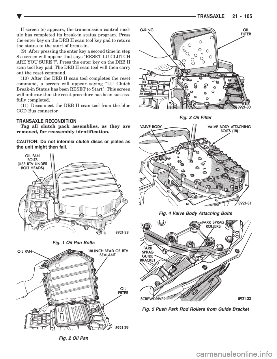
TRANSAXLE RECONDITION
Tag all clutch pack assemblies, as they are
removed, for reassembly identification.
CAUTION: Do not intermix clutch discs or plates as
the unit might then fail.
Fig. 1 Oil Pan Bolts
Fig. 2 Oil Pan
Fig. 3 Oil Filter
Fig. 4 Valve Body Attaching Bolts
Fig. 5 Push Park Rod Rollers from Guide Bracket
Ä TRANSAXLE 21 - 105
Page 2105 of 2438

41TE ON-BOARD DIAGNOSTICS INDEX
page page
CCD Bus .............................. 145
Diagnostic Trouble Code Charts ............ 146
Diagnostic Trouble Codes ................. 145
DRB II Scan Tool ....................... 146 General Information
...................... 145
Limp-In Mode .......................... 145
On-Board Diagnostics Information ........... 145
GENERAL INFORMATION
The information in this manual is designed to help
the technician understand and repair the transaxle
with the aid of the built in on-board diagnostics. Chrysler Corporation has developed a com-
plete set of diagnostic manuals which cover the
diagnosis of the 41TE transaxle. They have been
designed to make transaxle diagnosis accurate
and simple. Use these manuals with the DRB II
scan tool and the latest cartridge, when diagnos-
ing transaxle problems.
ON-BOARD DIAGNOSTICS INFORMATION
The 41TE transaxle is controlled and monitored by
the transmission control module. The transmission
control module monitors critical input and output
circuits within the transaxle. Some circuits are tested continuously; others are
checked only under certain conditions. Each circuit
monitored by the transmission control module has a
corresponding fault message assigned to it that can be
read with the DRB II scan tool. If the on-board diagnostic system senses that one of
the circuits is malfunctioning, the corresponding code
is stored in memory. If the malfunction goes away after
the code is stored, the transmission control module will
erase the code after 75 key cycles.
CCD BUS
In order to diagnose the 41TE transaxle, diagnostic
trouble codes in the transmission control module's
memory should be read. Use the Diagnostic Readout
Box (DRB II) scan tool to read codes. If more than one
diagnostic trouble code exists, diagnostic priority
should be given to the most recent code. With CCD bus
bias and communication problems, the DRB II scan
tool displays an appropriate message. Diagnostic
trouble codes might not be accessible until the bus
problem is fixed. The following is a list of probable
causes for a bus problem:
² Open or short to ground/battery in either or both
CCD bus wires (pins 4 and 43).
² Open or short to ground/battery in either or both
41TE transaxle's bias wires (pin 5 and 44) on vehicles
requiring the transaxle to bias the bus.
² Open or short to ground/battery in the diagnostic
connector bus wire. ²
Internal failure of any module connected to the bus.
The CCD bus should have 2.5 volts (+2.5 volts on
CCD+ and -2.5 volts on CCD-). The bus error message displayed by the DRB II scan
tool should be helpful in diagnosing the CCD bus. For more information on diagnosing CCD bus prob-
lems, refer to the 1993 Diagnostic Procedures Manual
(non-communication with the CCD bus). All other
problems refer to the 1993 Body Vehicle Communica-
tions Diagnostic Procedures Manual.
DIAGNOSTIC TROUBLE CODES
Diagnostic Trouble Codes are two-digit numbers that
identify which circuit is malfunctioning. A code can be
set for hydraulic and mechanical reasons as well as for
electrical problems. In most cases, codes do not pin-
point which specific component is defective. Diagnostic trouble codes can only be read with
the use of the DRB II scan tool or equivalent.
HARD FAULTS
Any Diagnostic trouble code that comes back within
3 engine starts (reset count 3 or less) is a ``Hard Fault''.
This means that the defect is there every time the
transmission control module checks that circuit.
SOFT FAULTS
A ``Soft Fault'' is one that occurs intermittently. It is
not there every time the transmission control module
checks the circuit. Most soft faults are caused by wiring
or connector problems. Intermittent defects must be
looked for under the specific conditions that caused
them.
LIMP-IN MODE
The transmission control module continuously
checks for electrical and internal transaxle problems.
When a problem is sensed, the transmission control
module stores a diagnostic trouble code. All but twelve
of these codes cause the transaxle to go into the
``Limp-in mode''. While in this mode, electrical power is
taken away from the transaxle. When this happens,
the only transaxle ranges that will function are:
Ä TRANSAXLE 21 - 145
Page 2338 of 2438

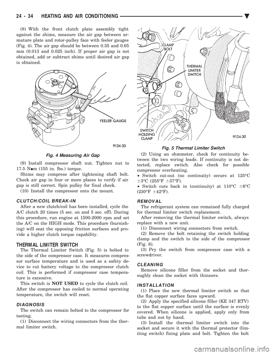
(8) With the front clutch plate assembly tight
against the shims, measure the air gap between ar-
mature plate and rotor-pulley face with feeler gauges
(Fig. 4). The air gap should be between 0.35 and 0.65
mm (0.013 and 0.025 inch). If proper air gap is not
obtained, add or subtract shims until desired air gap
is obtained.
(9) Install compressor shaft nut. Tighten nut to
17.5 N Im (155 in. lbs.) torque.
Shims may compress after tightening shaft bolt.
Check air gap in four or more places to verify if air
gap is still correct. Spin pulley for final check. (10) Install the compressor onto the mount.
CLUTCH/COIL BREAK-IN
After a new clutch/coil has been installed, cycle the
A/C clutch 20 times (5 sec. on and 5 sec. off). During
this procedure, run engine at 1500-2000 rpm and set
the A/C on the HIGH mode. This procedure (burnish-
ing) will seat the opposing friction surfaces and pro-
vide a higher clutch torque capability.
THERMAL LIMITER SWITCH
The Thermal Limiter Switch (Fig. 5) is bolted to
the side of the compressor case. It measures compres-
sor surface temperature and is used as a safety de-
vice to cut battery voltage to the compressor clutch
coil. This is performed if compressor case tempera-
ture is excessive. This switch is NOT USEDto cycle the clutch coil.
After the compressor has cooled to normal operating
temperature, the switch will reset.
DIAGNOSIS
The switch can remain bolted to the compressor for
testing. (1) Disconnect the wiring connectors from the ther-
mal limiter switch. (2) Using an ohmmeter, check for continuity be-
tween the two wiring leads. If continuity is not de-
tected, replace switch. Also check for possible
compressor overheating.
² Switch cut-out (no continuity) occurs at 125ÉC
6 3ÉC (255ÉF 637ÉF).
² Switch cuts back in (continuity) at 110ÉC 66ÉC
(230ÉF 642ÉF).
REMOVAL
The refrigerant system can remained fully charged
for thermal limiter switch replacement. After removing the thermal limiter switch, always
replace with a new unit. (1) Disconnect wiring connectors from switch.
(2) Remove the bolt retaining the switch holding
clamp and the switch to the side of the compressor
(Fig. 6). (3) Pry the switch from compressor case with a
screwdriver.
CLEANING
Remove silicone filler from the socket and thor-
oughly clean the socket with thinners.
INSTALLATION
(1) Place the new thermal limiter switch so that
the flat copper surface faces upward. (2) Apply the specified silicone filler (KE 347 RTV)
to the flat copper surface until the surface is evenly
covered. When silicone is applied, apply only from
tube and not by hand. (3) Install the thermal limiter switch into the
socket and secure it with the thermal protector (lim-
iting switch) fixing plate and bolt. Tighten the bolt
Fig. 4 Measuring Air Gap
Fig. 5 Thermal Limiter Switch
24 - 34 HEATING AND AIR CONDITIONING Ä