1993 CHEVROLET PLYMOUTH ACCLAIM reset
[x] Cancel search: resetPage 756 of 2438

(5) Reset the terminal locking tang, if it has one.
(6) Insert the removed wire in the same cavity on
the repair connector. (7) Repeat steps four thru six for each wire in the
connector. Check that all wires are inserted into the
proper cavities. For connector pin out identification
refer to the wiring diagrams. (8) Insert the connector locking wedge into the re-
paired connector. (9) Connect connector to its mating half.
(10) Connect battery and test all affected systems.
CONNECTOR AND TERMINAL ASSEMBLY REPLACEMENT
(1) Disconnect Battery.
(2) Disconnect the connector being repaired form
its mating half. (3) Cut off the existing wire connector directly be-
hind the insulator. Remove six inches of tape from
the harness. (4) Stagger cut all wires on the harness side about
1/2 inch apart (Fig. 14). (5) Remove 1 inch of insulation from each wire on
the harness side. (6) Stagger cut the matching wires on the repair
connector assembly in the opposite order as was done
on the harness side of the repair. Allow extra length
for soldered connections. Check that the overall
length is the same as the original (Fig. 14). (7) Remove 1 inch of insulation from each wire.
(8) Place a piece of heat shrink tubing over one
side of the wire. Make sure the tubing will be long
enough to cover and seal the entire repair area. (9) Spread the strands of the wire apart on each
part of the exposed wires (Fig. 11 example 1). (10) Push the two ends of wire together until the
strands of wire are close to the insulation (Fig. 11 ex-
ample 2). (11) Twist the wires together (Fig. 11 example 3). (12) Solder the connection together using rosin
core type solder only. Do not use acid core solder.
(13) Center the heat shrink tubing over the joint
and heat using a heat gun. Heat the joint until the
tubing is tightly sealed and sealant comes out of both
ends of the tubing. (14) Repeat steps 8 thru 13 for each wire.
(15) Re-tape the wire harness starting 1-1/2 inches
behind the connector and 2 inches past the repair. (16) Reconnect the repaired connector.
(17) Connect battery and test all affected systems.
TERMINAL REPLACEMENT
(1) Disconnect battery.
(2) Disconnect the connector being repaired form
its mating half. (3) Remove connector locking wedge (Fig. 12).
(4) Position the connector locking finger away from
the terminal. Pull on the wire to remove the termi-
nal from the connector (Fig. 13). (5) Cut the wire 6 inches from the back of the con-
nector. (6) Remove 1 inch of insulation from the wire on
the harness side. (7) Select a wire from the terminal repair assem-
bly that best matches the color wire being repaired. (8) Cut the repair wire to the proper length and re-
move 1 inch of insulation. (9) Place a piece of heat shrink tubing over one
side of the wire. Make sure the tubing will be long
enough to cover and seal the entire repair area. (10) Spread the strands of the wire apart on each
part of the exposed wires (Fig. 11 example 1). (11) Push the two ends of wire together until the
strands of wire are close to the insulation (Fig. 11 ex-
ample 2). (12) Twist the wires together (Fig. 11 example 3).
(13) Solder the connection together using rosin
core type solder only. Do not use acid core solder.
Fig. 13 Connector Locking Finger and Locking
Wedge
Fig. 14 Stagger Cutting Wires
8W - 6 GENERAL INFORMATION Ä
Page 1582 of 2438
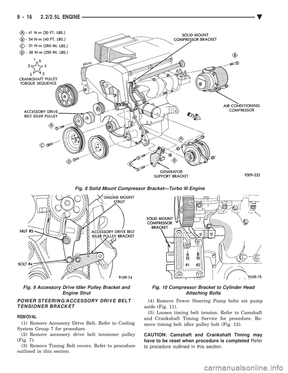
POWER STEERING/ACCESSORY DRIVE BELT TENSIONER BRACKET
REMOVAL
(1) Remove Accessory Drive Belt. Refer to Cooling
System Group 7 for procedure. (2) Remove accessory drive belt tensioner pulley
(Fig. 7). (3) Remove Timing Belt covers. Refer to procedure
outlined in this section. (4) Remove Power Steering Pump bolts set pump
aside (Fig. 11). (5) Loosen timing belt tension. Refer to Camshaft
and Crankshaft Timing Service for procedure. Re-
move timing belt idler pulley bolt (Fig. 12).
CAUTION: Camshaft and Crankshaft Timing may
have to be reset when procedure is completed Refer
to procedure outlined in this section.
Fig. 8 Solid Mount Compressor BracketÐTurbo III Engine
Fig. 9 Accessory Drive Idler Pulley Bracket and Engine StrutFig. 10 Compressor Bracket to Cylinder HeadAttaching Bolts
9 - 16 2.2/2.5L ENGINE Ä
Page 1587 of 2438
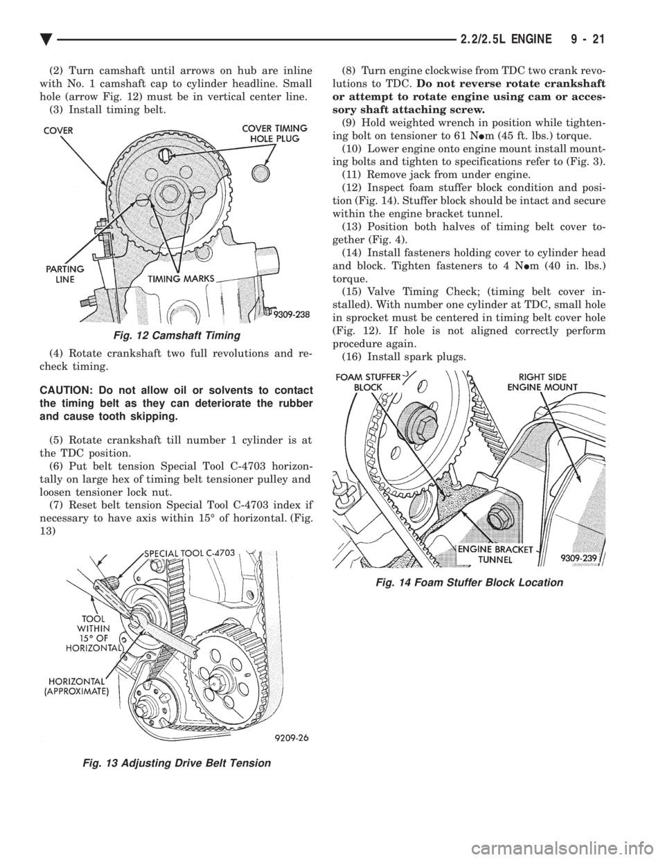
(2) Turn camshaft until arrows on hub are inline
with No. 1 camshaft cap to cylinder headline. Small
hole (arrow Fig. 12) must be in vertical center line. (3) Install timing belt.
(4) Rotate crankshaft two full revolutions and re-
check timing.
CAUTION: Do not allow oil or solvents to contact
the timing belt as they can deteriorate the rubber
and cause tooth skipping.
(5) Rotate crankshaft till number 1 cylinder is at
the TDC position. (6) Put belt tension Special Tool C-4703 horizon-
tally on large hex of timing belt tensioner pulley and
loosen tensioner lock nut. (7) Reset belt tension Special Tool C-4703 index if
necessary to have axis within 15É of horizontal. (Fig.
13) (8) Turn engine clockwise from TDC two crank revo-
lutions to TDC. Do not reverse rotate crankshaft
or attempt to rotate engine using cam or acces-
sory shaft attaching screw. (9) Hold weighted wrench in position while tighten-
ing bolt on tensioner to 61 N Im (45 ft. lbs.) torque.
(10) Lower engine onto engine mount install mount-
ing bolts and tighten to specifications refer to (Fig. 3). (11) Remove jack from under engine.
(12) Inspect foam stuffer block condition and posi-
tion (Fig. 14). Stuffer block should be intact and secure
within the engine bracket tunnel. (13) Position both halves of timing belt cover to-
gether (Fig. 4). (14) Install fasteners holding cover to cylinder head
and block. Tighten fasteners to 4 N Im (40 in. lbs.)
torque. (15) Valve Timing Check; (timing belt cover in-
stalled). With number one cylinder at TDC, small hole
in sprocket must be centered in timing belt cover hole
(Fig. 12). If hole is not aligned correctly perform
procedure again. (16) Install spark plugs.
Fig. 12 Camshaft Timing
Fig. 13 Adjusting Drive Belt Tension
Fig. 14 Foam Stuffer Block Location
Ä 2.2/2.5L ENGINE 9 - 21
Page 1772 of 2438
TACHOMETERÐPCM OUTPUT
The PCM supplies engine RPM to the instrument
panel tachometer. Refer to Group 8 for tachometer
information.
MODES OF OPERATION
As input signals to the PCM change, the PCM
adjusts its response to the output devices. For example,
the PCM must calculate a different injector pulse
width and ignition timing for idle than it does for wide
open throttle (WOT). There are several different modes
of operation that determine how the PCM responds to
the various input signals. There are two different areas of operation, OPEN
LOOP and CLOSED LOOP. During OPEN LOOP modes, the PCM receives input
signals and responds according to preset PCM pro-
gramming. Input from the oxygen (O
2) sensor is not
monitored during OPEN LOOP modes. During CLOSED LOOP modes, the PCM does moni-
tor the oxygen (O
2) sensor input. This input tells the
PCM if the calculated injector pulse width results in an
air-fuel ratio of 14.7 to 1. By monitoring the exhaust
oxygen content, the can PCM fine tune injector pulse
width for optimum fuel economy and low emissions. The single point fuel injection system has the follow-
ing modes of operation:
² Ignition switch ON - Zero RPM
² Engine start-up
² Engine warm-up
² Cruise (Idle)
² Acceleration
² Deceleration
² Wide Open Throttle
² Ignition switch OFF
The engine start-up (cranking), engine warm-up, and
wide open throttle modes are OPEN LOOP modes. The
acceleration, deceleration, and cruise modes, with the
engine at operating temperature are CLOSED
LOOP modes (under most operating conditions).
IGNITION SWITCH ON (ZERO RPM) MODE
When the single point fuel injection system is acti-
vated by the ignition switch, the following actions
occur:
² The PCM determines atmospheric air pressure from
the MAP sensor input to calculate basic fuel strategy.
² The PCM monitors the coolant temperature sensor
and throttle position sensor inputs. The PCM modifies
fuel strategy based on these inputs. When the key is in the ON position and the engine is
not running, the (ASD) and fuel pump relays are not
energized. Therefore, battery voltage is not supplied to
the fuel pump, ignition coil, fuel injector or oxygen
sensor heating element. ENGINE START-UP MODE
This is an OPEN LOOP mode. The following actions
occur when the starter motor is engaged. If the PCM receives a distributor signal it energizes
the auto shutdown (ASD) relay and fuel pump relay to
supply battery voltage to the fuel injector, ignition coil
and oxygen sensor heating element. If the PCM does
not receive a distributor input, it de-energizes the ASD
and fuel pump relays after approximately one second. When the engine idles within 664 RPM of the target
RPM, the PCM compares the current MAP value with
the atmospheric pressure value it received during the
Ignition Switch On (Zero RPM) Mode. If a minimum
difference between the two is not detected, a MAP
sensor fault is set into memory. Once the ASD relay and fuel pump relay have ener-
gized, the PCM:
² Supplies a ground path to the injector. The injector
is pulsed four times per engine revolution instead of
the normal two pulses per revolution.
² Determines injector pulse width based on coolant
temperature, MAP sensor input, throttle position, and
the number of engine revolutions since cranking was
initiated.
² Monitors the coolant temperature sensor, distribu-
tor pick-up, MAP sensor, and throttle position sensor to
determine correct ignition timing.
ENGINE WARM-UP MODE
This is a OPEN LOOP mode. The following inputs
are received by the PCM:
² coolant temperature
² manifold absolute pressure (MAP)
² engine speed (distributor pick-up)
² throttle position
² A/C switch
² battery voltage
The PCM provides a ground path for the injector to
precisely control injector pulse width (by switching the
ground on and off) and fires the injector twice per
engine revolution. The PCM regulates ignition timing.
It also adjusts engine idle speed through the idle air
control motor.
CRUISE OR IDLE MODE
When the engine is at operating temperature this is
a CLOSED LOOP mode. During cruising speed and at
idle the following inputs are received by the PCM:
² coolant temperature
² manifold absolute pressure
² engine speed
² throttle position
² exhaust gas oxygen content
² A/C control positions
² battery voltage
14 - 32 FUEL SYSTEMS Ä
Page 1803 of 2438
mode, the PCM compensates for the failure of certain
components that send incorrect signals. The PCM
substitutes for the incorrect signals with inputs from
other sensors and by using stored default values.Signals that can trigger the Malfunction Indi-
cator (Check Engine) Lamp.
² An emission system component
² Battery Voltage Input
² Charging system
² Engine Coolant Temperature Sensor
² Manifold Absolute Pressure Sensor
² Methanol Concentration Sensor
² Throttle Position Sensor
The malfunction indicator lamp can also display
diagnostic trouble codes. Cycle the ignition switch on,
off, on, off, on, within five seconds and the PCM
displays any diagnostic trouble codes stored in
memory. Refer to the 2.5L Flexible Fuel Multi-Port
Fuel InjectionÐOn Board Diagnostics section in this
group for diagnostic trouble code descriptions.
RADIATOR FAN RELAYÐPCM OUTPUT
The radiator fan is energized by the PCM through
the radiator fan relay. The PCM grounds the radiator
fan relay when engine coolant reaches a predetermined
temperature. For more information, refer to Group 7,
Cooling Systems. The radiator fan relay is mounted on the drivers side
fender well, next to the strut tower (Fig. 11).
SPEED CONTROL SOLENOIDSÐPCM OUTPUT
The speed control vacuum and vent solenoids are
operated by the PCM. When the PCM supplies a
ground to the vacuum and vent solenoids, the speed
control system opens the throttle blade. When the PCM
supplies a ground only to the vent solenoid, the throttle
blade holds position. When the PCM removes the
ground from both the vacuum and vent solenoids, the
throttle blade closes. The PCM balances the two sole-
noids to maintain the set speed. Refer to Group 8H for
speed control information.
TACHOMETERÐPCM OUTPUT
The PCM supplies engine RPM to the instrument
panel tachometer. Refer to Group 8 for tachometer
information.
TORQUE CONVERTER CLUTCH SOLENOIDÐPCM
OUTPUT
Three-speed automatic transaxles use a torque con-
verter clutch solenoid. The PCM controls the lock-up of
the torque convertor through the solenoid. The tran-
saxle is locked up only in direct drive mode. Refer to
Group 21 for transaxle information.
MODES OF OPERATION
As input signals to the PCM change, the PCM
adjusts its response to the output devices. For example, the PCM must calculate a different injector pulse
width and ignition timing for idle than it does for wide
open throttle (WOT). There are several different modes
of operation that determine how the PCM responds to
the various input signals. There are two different areas of operation, Open
Loop and Closed Loop. During Open Loop modes, the PCM receives input
signals and responds according to preset PCM pro-
gramming. Input from the oxygen (O
2) sensor is not
monitored during Open Loop modes. During CLOSED LOOP modes, the PCM does moni-
tor the oxygen (O
2) sensor input. The input indicates if
the calculated injector pulse width results in the ideal
air-fuel ratio for the current percentage of methanol in
the fuel. By monitoring the exhaust oxygen content
through the O
2sensor, the PCM can fine tune the
injector pulse width to achieve optimum fuel economy
combined with low emissions. The 2.5L flexible fuel multi-port fuel injection system
has the following modes of operation:
² Ignition switch ON - Zero RPM
² Engine start-up
² Engine warm-up
² Cruise (Idle)
² Acceleration
² Deceleration
² Wide Open Throttle
² Ignition switch OFF
The engine start-up (crank), engine warm-up, and
wide open throttle modes are OPEN LOOP modes. The
acceleration, deceleration, and cruise modes, with the
engine at operating temperature are CLOSED
LOOP modes (under most operating conditions).
IGNITION SWITCH ON (ZERO RPM) MODE
When the ignition switch cycles and past the On
position, the fuel injection system activates and the
following actions occur:
² For two seconds at key ON (and during cranking),
the methanol concentration sensor calibrates the PCM.
During the calibration period the sensor sends 4.45
volts to the PCM as a correction factor. After the
calibration period, the methanol concentration sensor
output represents the methanol percentage in the fuel.
² The PCM calculates basic fuel strategy by determin-
ing atmospheric air pressure from the MAP sensor
input.
² The PCM monitors the coolant temperature sensor
and throttle position sensor input. The PCM modifies
fuel strategy based on this input. When the key is in the ON position and the engine is
not running, the auto shutdown (ASD) relay and fuel
pump relay are not energized. Therefore battery volt-
age is not supplied to the fuel pump, ignition coil, fuel
injector or oxygen sensor heating element.
Ä FUEL SYSTEMS 14 - 63
Page 1832 of 2438

noid is energized. The solenoid mounts to the passen-
ger side inner fender panel, next to the strut tower
(Fig. 17).
MODES OF OPERATION
As input signals to the PCM change, the PCM
adjusts its response to the output devices. For example,
the PCM must calculate a different injector pulse
width and ignition timing for idle than it does for wide
open throttle (WOT). There are several different modes
of operation that determine how the PCM responds to
the various input signals. There are two different areas of operation, OPEN
LOOP and CLOSED LOOP. During OPEN LOOP modes, the PCM receives input
signals and responds according to preset PCM pro-
gramming. Input from the oxygen (O
2) sensor is not
monitored during OPEN LOOP modes. During CLOSED LOOP modes, the PCM does moni-
tor the oxygen (O
2) sensor input. This input indicates
to the PCM whether or not the calculated injector pulse
width results in the ideal air-fuel ratio of 14.7 parts air
to 1 part fuel. By monitoring the exhaust oxygen
content through the O
2sensor, the PCM can fine tune
the injector pulse width to achieve optimum fuel
economy combined with low emissions. The 2.2L Turbo III multi-port fuel injection system
has the following modes of operation:
² Ignition switch ON - Zero RPM
² Engine start-up
² Engine warm-up
² Cruise (Idle)
² Acceleration
² Deceleration
² Wide Open Throttle
² Ignition switch OFF
The engine start-up (crank), engine warm-up, and
wide open throttle modes are OPEN LOOP modes. The
acceleration, deceleration, and cruise modes, with the
engine at operating temperature are CLOSED
LOOP modes (under most operating conditions).
IGNITION SWITCH ON (ZERO RPM) MODE
When the ignition switch activates the fuel injection
system the following actions occur:
²
The PCM calculates basic fuel strategy by determining
atmospheric air pressure from the MAP sensor input.
² The PCM monitors the coolant temperature sensor
and throttle position sensor input. The PCM modifies
fuel strategy based on this input. When the key is in the ON position and the engine is
not running, the auto shutdown (ASD) relay and fuel
pump relay are not energized. Therefore battery volt-
age is not supplied to the fuel pump, ignition coil, fuel
injector or oxygen sensor heating element.
ENGINE START-UP MODE
This is an OPEN LOOP mode. The following actions
occur when the starter motor is engaged. If the PCM receives the camshaft position and crank-
shaft position sensor signals, it energizes the auto
shutdown (ASD) relay and fuel pump relay. These
relays supply battery voltage to the fuel pump, fuel
injectors, ignition coil, and oxygen sensor heating ele-
ment. If the PCM does not receive the camshaft posi-
tion sensor and crankshaft position sensor signals
within approximately one second, it de-energizes the
ASD relay and fuel pump relay. The PCM energizes all injectors until it determines
crankshaft position from the camshaft position sensor
and crankshaft position sensor signals. The PCM de-
termines crankshaft position within 1 engine revolu-
tion. After determining crankshaft position, the PCM be-
gins energizing the injectors in sequence. The PCM
adjusts injector pulse width and controls injector syn-
chronization by turning the individual ground paths to
the injectors On and Off. When the engine idles within 664 RPM of its target
RPM, the PCM compares current MAP sensor value
with the atmospheric pressure value received during
the Ignition Switch On (zero RPM) mode. If the PCM
does not detect a minimum difference between the two
values, it sets a MAP fault into memory. Once the ASD and fuel pump relays have been
energized, the PCM:
² Determines injector pulse width based on coolant
temperature, manifold absolute pressure (MAP) and
the number of engine revolutions since cranking was
initiated.
² Monitors the coolant temperature sensor, camshaft
position sensor, crankshaft position sensor, MAP sen-
sor, and throttle position sensor to determine correct
ignition timing.
ENGINE WARM-UP MODE
This is a OPEN LOOP mode. The following inputs
are received by the PCM:
² engine coolant temperature
² knock sensor
² manifold absolute pressure (MAP)
² engine speed (crankshaft position sensor)
² throttle position
² A/C switch
² battery voltage
The PCM provides a ground path for the injectors to
precisely control injector pulse width (by switching the
ground on and off). The PCM adjusts engine idle speed
through the idle air control motor. Also, the PCM
regulates ignition timing.
14 - 92 FUEL SYSTEMS Ä
Page 1834 of 2438
THROTTLE BODY
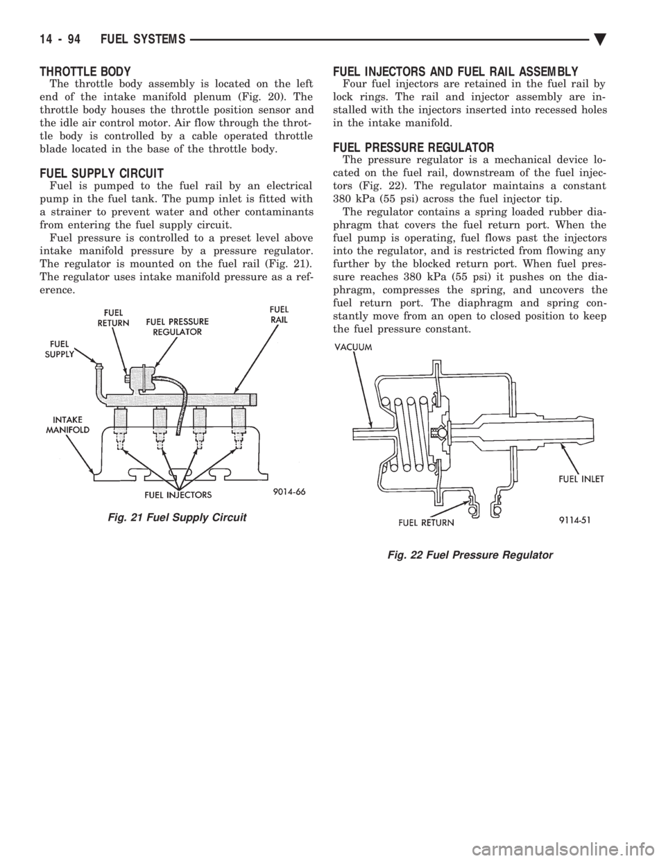
The throttle body assembly is located on the left
end of the intake manifold plenum (Fig. 20). The
throttle body houses the throttle position sensor and
the idle air control motor. Air flow through the throt-
tle body is controlled by a cable operated throttle
blade located in the base of the throttle body.
FUEL SUPPLY CIRCUIT
Fuel is pumped to the fuel rail by an electrical
pump in the fuel tank. The pump inlet is fitted with
a strainer to prevent water and other contaminants
from entering the fuel supply circuit. Fuel pressure is controlled to a preset level above
intake manifold pressure by a pressure regulator.
The regulator is mounted on the fuel rail (Fig. 21).
The regulator uses intake manifold pressure as a ref-
erence.
FUEL INJECTORS AND FUEL RAIL ASSEMBLY
Four fuel injectors are retained in the fuel rail by
lock rings. The rail and injector assembly are in-
stalled with the injectors inserted into recessed holes
in the intake manifold.
FUEL PRESSURE REGULATOR
The pressure regulator is a mechanical device lo-
cated on the fuel rail, downstream of the fuel injec-
tors (Fig. 22). The regulator maintains a constant
380 kPa (55 psi) across the fuel injector tip. The regulator contains a spring loaded rubber dia-
phragm that covers the fuel return port. When the
fuel pump is operating, fuel flows past the injectors
into the regulator, and is restricted from flowing any
further by the blocked return port. When fuel pres-
sure reaches 380 kPa (55 psi) it pushes on the dia-
phragm, compresses the spring, and uncovers the
fuel return port. The diaphragm and spring con-
stantly move from an open to closed position to keep
the fuel pressure constant.
Fig. 21 Fuel Supply Circuit
Fig. 22 Fuel Pressure Regulator
14 - 94 FUEL SYSTEMS Ä
Page 1861 of 2438
tially energizes all injectors at the same time. Once
the PCM determines crankshaft position, it begins
energizing the injectors in sequence.Battery voltage is supplied to the injectors through
the ASD relay. The PCM provides the ground path
for the injectors. By switching the ground path on
and off, the PCM adjusts injector pulse width. Pulse
width is the amount of time the injector is energized.
The PCM adjusts injector pulse width based on in-
puts it receives.
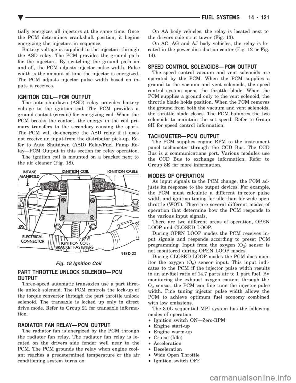
IGNITION COILÐPCM OUTPUT
The auto shutdown (ASD) relay provides battery
voltage to the ignition coil. The PCM provides a
ground contact (circuit) for energizing coil. When the
PCM breaks the contact, the energy in the coil pri-
mary transfers to the secondary causing the spark.
The PCM will de-energize the ASD relay if it does
not receive an input from the distributor pick-up. Re-
fer to Auto Shutdown (ASD) Relay/Fuel Pump Re-
layÐPCM Output in this section for relay operation. The ignition coil is mounted on a bracket next to
the air cleaner (Fig. 18).
PART THROTTLE UNLOCK SOLENOIDÐPCM
OUTPUT
Three-speed automatic transaxles use a part throt-
tle unlock solenoid. The PCM controls the lock-up of
the torque convertor through the part throttle unlock
solenoid. The transaxle is locked up only in direct
drive mode. Refer to Group 21 for transaxle informa-
tion.
RADIATOR FAN RELAYÐPCM OUTPUT
The radiator fan is energized by the PCM through
the radiator fan relay. The radiator fan relay is lo-
cated on the drivers side fender well near to the
PCM. The PCM grounds the relay when engine cool-
ant reaches a predetermined temperature or the air
conditioning system turns on. On AA body vehicles, the relay is located next to
the drivers side strut tower (Fig. 13). On AC, AG and AJ body vehicles, the relay is lo-
cated in the power distribution center (Fig. 12 or Fig.
14).
SPEED CONTROL SOLENOIDSÐPCM OUTPUT
The speed control vacuum and vent solenoids are
operated by the PCM. When the PCM supplies a
ground to the vacuum and vent solenoids, the speed
control system opens the throttle blade. When the
PCM supplies a ground only to the vent solenoid, the
throttle blade holds position. When the PCM removes
the ground from both the vacuum and vent solenoids,
the throttle blade closes. The PCM balances the two
solenoids to maintain the set speed. Refer to Group
8H for speed control information.
TACHOMETERÐPCM OUTPUT
The PCM supplies engine RPM to the instrument
panel tachometer through the CCD Bus. The CCD
Bus is a communications port. Various modules use
the CCD Bus to exchange information. Refer to
Group 8E for more information.
MODES OF OPERATION
As input signals to the PCM change, the PCM ad-
justs its response to the output devices. For example,
the PCM must calculate a different injector pulse
width and ignition timing for idle than for wide open
throttle (WOT). There are several different modes of
operation that determine how the PCM responds to
the various input signals. There are two different areas of operation, OPEN
LOOP and CLOSED LOOP. During OPEN LOOP modes the PCM receives in-
put signals and responds according to preset PCM
programming. Input from the oxygen (O
2) sensor is
not monitored during OPEN LOOP modes. During CLOSED LOOP modes the PCM does mon-
itor the oxygen (O
2) sensor input. This input indi-
cates to the PCM if the injector pulse width results
in an air-fuel ratio of 14.7 parts air to 1 part fuel. By
monitoring the exhaust oxygen content through the
O
2sensor, the PCM can fine tune the injector pulse
width. Fine tuning injector pulse width allows the
PCM to achieve optimum fuel economy combined
with low emissions. The 3.0L sequential MPI system has the following
modes of operation:
² Ignition switch ONÐZero-RPM
² Engine start-up
² Engine warm-up
² Cruise (Idle)
² Acceleration
² Deceleration
² Wide Open Throttle
² Ignition switch OFF
Fig. 18 Ignition Coil
Ä FUEL SYSTEMS 14 - 121