1993 CHEVROLET PLYMOUTH ACCLAIM radiator
[x] Cancel search: radiatorPage 687 of 2438

(2) Connect sensor wiring lead from harness to
connector on body of sensor. (3) Install coolant bottle, powertrain control mod-
ule, battery tray and battery. (4) Install speed control servo to battery tray, if
equipped. (5) Do not connect negative battery cable. Refer to
Air Bag Systems Check for proper procedure.
RIGHT FRONT IMPACT SENSOR
REMOVAL
(1) Disconnect battery ground cable and isolate.
(2) Disconnect impact sensor electrical connector
(Fig. 7).
(3) Remove three screws holding sensor to radiator
closure panel. Remove right sensor.
INSTALLATION
(1) Mount right sensor (arrow pointed forward) to
engine side of closure panel using three screws pro-
vided with the new sensor. Tighten 10 to 13 N Im (90-
120 in. lbs.) torque. (2) Connect sensor wiring lead from harness to
connector on body of sensor. (3) Do not connect negative battery cable. Refer to
Air Bag Systems Check for proper procedure.
AIR BAG SYSTEM DIAGNOSTIC MODULE (ASDM)
WARNING: THE ASDM CONTAINS ONE OF THE IM-
PACT SENSORS WHICH ENABLE THE SYSTEM TO
DEPLOY THE AIR BAG. TO AVOID ACCIDENTAL
DEPLOYMENT, NEVER CONNECT ASDM ELECTRI- CALLY TO THE SYSTEM UNLESS IT IS BOLTED TO
VEHICLE. BEFORE BEGINNING ANY AIR BAG SYS-
TEM REMOVAL OR INSTALLATION PROCEDURES,
REMOVE AND ISOLATE THE BATTERY NEGATIVE
(-) CABLE (GROUND) FROM THE VEHICLE BAT-
TERY. THIS IS THE ONLY SURE WAY TO DISABLE
THE AIR BAG SYSTEM. FAILURE TO DO THIS
COULD RESULT IN ACCIDENTAL AIR BAG DE-
PLOYMENT, AND POSSIBLE PERSONAL INJURY.
REMOVAL
(1) Disconnect battery ground cable, and isolate.
(2) Remove forward console bezel (Fig. 8).
(3) Remove two screws from right side console be-
zel and remove bezel. (4) Disconnect wiring at ASDM.
(5) Remove module mounting screws, and remove
module.
INSTALLATION
(1) Position the ASDM with the arrow pointing
forward on the console reinforcement. Insert tab on
the ASDM in the slot on the reinforcement. (2) Attach the ASDM to the support bracket with
the screws supplied and tighten to 1.7 to 2 N In
(15-20 in. lbs.) torque. (3) Connect wiring at ASDM, making sure both
connectors are seated and locking tabs engaged. (4) Install right side console bezel.
(5) Install forward console bezel.
(6) Do not connect negative battery cable. Refer to
Air Bag System Check for proper procedure.
Fig. 7 Right Impact Sensor
Fig. 8 Air Bag System Diagnostic Module (ASDM)
Ä RESTRAINT SYSTEMS 8M - 5
Page 787 of 2438

AC BODY C,D
Caption Fig.
Air Suspension Wiring ..........................4
Body Left Side Wiring ...........................8
Body Right Side Wiring ..........................9
Cellular Phone Wiring ...........................7
Deck Lid Wiring ..............................5
Door Wiring (Body) ...........................10
Door Wiring (Front) ...........................11
Door Wiring (Rear) ............................12
Engine Wiring 2.5L ............................27
Engine Wiring 3.0L ............................28
Engine Wiring 3.3L, 3.8L ........................29
Engine Compartment Wiring 2.5L ................18, 19
Engine Compartment Wiring 3.0L .............20, 22, 23
Engine Compartment Wiring 3.3L, 3.8L ..........21, 22, 23Caption Fig.
Front End Lighting (Aero Headlamps) ................32
Front End Lighting (Concealed Headlamps) ............33
Ground Strap Locations .........................30
Heated Rear Window Wiring .......................6
Instrument Panel Wiring .................. .13, 14, 15
Load Leveling Wiring ...........................3
Radiator Fan Assembly .........................31
Rear End Wiring (Chrysler) .......................1
Rear End Wiring (Dodge) ........................2
Steering Column Wiring .........................16
Transmission Wiring 2.5L .......................24
Transmission WIring 3.0L .......................25
Transmission Wiring 3.3L, 3.8L ....................26
Underhood Lamp Wiring ........................17
Ä WIRING AND COMPONENT IDENTIFICATION 8W - 37
Page 808 of 2438
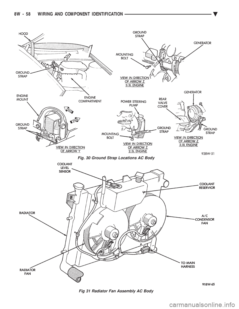
Fig. 30 Ground Strap Locations AC Body
Fig 31 Radiator Fan Assembly AC Body
8W - 58 WIRING AND COMPONENT IDENTIFICATION Ä
Page 861 of 2438
AY BODY-C
Caption Fig.
Air Suspension Wiring ..........................3
Body Left Side Wiring ...........................8
Body Right Side Wiring ..........................9
Cellular Phone Wiring ...........................7
Deck Lid Wiring ..............................5
Door Wiring (Body) ...........................10
Door Wiring (Front) ...........................11
Door Wiring (Rear) ............................12
Engine Wiring 3.3L and 3.8L .....................23
Engine Compartment Wiring 3.3L and 3.8L .......18, 19, 20Caption Fig.
Front End Lighting ............................24
Ground Strap Locations .........................6
Heated Rear Window Wiring .......................4
Instrument Panel Wiring .................. .13, 14, 15
Load Leveling Wiring ...........................2
Radiator Fan Assembly .........................21
Rear End Wiring ..............................1
Steering Column Wiring .........................16
Transmission Wiring 3.3L and 3.8L .................22
Underhood Lamp Wiring ........................17
Ä WIRING AND COMPONENT IDENTIFICATION 8W - 111
Page 875 of 2438

Fig. 20 Engine Compartment Wiring 3.3L and 3.8L AY Body
Fig 21 Radiator Fan Assembly AY Body
Ä WIRING AND COMPONENT IDENTIFICATION 8W - 125
Page 931 of 2438
WIRING DIAGRAMS AA-BODY
INDEX
Wiring Diagram
Name Sheet Number
Airbag System ...............................47
Clockspring ...............................47
Diagnostic Module ..........................47
Interface Grommet ..........................47
Sensor-Left ...............................47
Sensor-Right ..............................47
Squibb ..................................47
Air Conditioning Compressor ...................32, 33
Air Conditioning System (2.5L Engine) ...............71
A/C Cycling Switch ..........................71
Blower Motor ..............................71
Blower Switch .............................71
Control Switch .............................71
Damped Pressure Switch ......................71
Defrost Switch .............................71
Illumination Lamp ...........................71
Resistor .................................71
Air Conditioning System (3.0L Engine) ...............72
A/C Switch ...............................72
Blower Motor ..............................72
Blower Switch .............................72
Control Switch .............................72
Damped Pressure Switch ......................72
Defrost Switch .............................72
High Pressure Switch ........................72
Illumination Lamp ...........................72
Resistor .................................72
Anti-Lock Brake System .................41, 42, 43, 44
ABS Pump Motor Relay .......................41
ABS System Relay ..........................43
ABS Warning Lamp Relay ......................43
Brake Switch ..............................44
Controller ....................... .41, 42, 43, 44
Hydraulic Modulator .........................41
Ignition Switch .............................44
Park Brake Switch ...........................44
Wheel Sensors .............................42
Ash Receiver Lamp ...........................52
Automatic Shut-down Relay .................14, 20, 28
Automatic Transmission Park/Neutral Position and Back-Up Lamp Switch ...............................9
Back-Up Lamp Switch ..........................9
Battery ............................1,5,7,39,40
Blower Motor-A/C ............................71
Blower Motor-Heater ...........................71
Brake Switch ...............................44
Brake Warning Lamp Switch ......................11
Bulkhead Disconnect (50-Way) ................112, 113
Center High Mounted Stop Lamp ..........94, 98, 102, 105
Charging System (2.5L) ........................5,6
Battery ...................................5
Generator .................................6Wiring Diagram
Name Sheet Number
Heated Rear Window Switch .....................5
Charging System (3.0L) ........................7,8
Battery ....................................7
Generator .................................8
Ignition Off-Draw Connector .....................7
Cigar Lighter ................................45
Cigar Lighter Lamp ............................52
Circuit Breaker (30 Amp) Fuseblock Cavity #10 .......67, 82
Circuit Breaker (30 Amp) Fuseblock Cavity #13 . . .2, 66, 67, 86
Clockspring ............................. .47, 59
Cluster Printed Circuit Board .................119, 120
Cluster Printed Circuit Board Connectors .............118
Courtesy Lamps .............................76
Daytime Running Light Module ....................57
Deck Lid Ajar Switch ..........................78
Dimmer Switch-Headlamp .....................1,50
Distributor ......................... .15, 21, 22, 27
EGR Solenoid ...............................24
Electrically Heated Rear Window ...................84
Heated Rear Window .........................84
Switch ..................................84
Timer ...................................84
Electronically Tuned Stereo Radio without Name Brand Speakers ................................87
Electronically Tuned Stereo Radio with Name Brand Speakers ................................89
Speaker Choke .............................89
Speaker Relay .............................89
Electronic Cluster ........................... .121
Engine Coolant Sensor ................... .15, 21, 27
Engine Oil and Temperature Warning System (2.5L) .......39
Engine Oil and Temperature Warning System (3.0L) .......40
Engine Oil Pressure Switch/Sending Unit ...........39, 40
Engine Temperature Sending Unit ................39, 40
Engine Starter System (2.5L Engine & 3.0L ATX) .......9,10
Automatic Transmission Park/Neutral Position Switch .....9
Backup Lamp Switch ..........................9
EMCC Solenoid .............................9
Engine Starter Relay ..........................9
Manual Transmission Back-Up Lamp Switch ...........9
Permanent Magnet Engine Starter Motor .............9
Engine Temperature Sending Unit ................39, 40
Exhaust Gas Recirculation Diagnostic Solenoid ........13, 24
Fan Control System with A/C and Heater System (2.5L) ....32
A/C Compressor ............................32
A/C Compressor Clutch Relay ...................32
A/C High Pressure Switch ......................32
Fan Control Relay ...........................32
Radiator Fan Motor ..........................32
Fan Control System with A/C and Heater System (3.0L) ....33
A/C Conditioning Compressor ...................33
A/C Compressor Clutch Relay ...................33
Ä WIRING DIAGRAMS AA-BODY 8W - 181
Page 932 of 2438
Wiring Diagram
Name Sheet Number
Fan Control Relay ...........................33
Radiator Fan Motor ..........................33
Fog Lamps ............................. .55, 56
Fog Lamp Relay .............................48
Fog Lamp Switch .............................48
Front End Lighting ........................ .55, 56
Front Left Side Marker Lamp ....................56
Front Right Side Marker Lamp ...................55
Left Aero Hi-Low Beam Headlamp .................56
Left Fog Lamp .............................56
Left Park & Turn Signal Lamp ...................56
Right Aero Hi-Low Beam Headlamp ................55
Right Fog Lamp ............................55
Right Park & Turn Signal Lamp ..................55
Fuel Injection Ignition System (2.5L) .......12, 13, 14, 15, 16
Automatic Shutdown Relay ......................14
Distributor ................................15
Engine Coolant Sensor ........................15
EVAP/Purge Solenoid .........................13
Exhaust Gas Recirculation Diagnostic Solenoid .........13
Heated Oxygen Sensor ........................12
Idle Air Control Motor .........................12
Ignition Coil ...............................14
Injector ..................................16
MAP Sensor ...............................13
Powertrain Control Module ............12, 13, 14, 15, 16
Throttle Position (Sensor) ......................12
Vehicle Speed Senosr .........................15
Fuel Injection Ignition System Flex Fuel (2.5L Engine) ................ .17, 18, 19, 20, 21, 22
Auto Shutdown Relay ........................20
Distributor ...............................22
Engine Coolant Sensor ........................21
EVAP/Purge Solenoid .........................19
Fuel Sensor ...............................17
Heated Oxygen Sensor ........................18
Idle Air Control Motor ........................18
Ignition Coil ...............................20
Injectors .................................17
MAP Sensor ..............................19
Powertrain Control Module (PCM) . . . .17, 18, 19, 20, 21, 22
Throttle Position (Sensor) ......................18
Vehicle Speed Sensor ........................21
Fuel Injection Ignition System (3.0L) ............. .23, 24, 25, 26, 27, 28, 29, 30, 31
Automatic Shutdown Relay .....................28
Distributor ...............................27
Engine Coolant Sensor ........................27
Exhaust Gas Recirculation Diagnostic Solenoid .........24
EVAP/Purge Solenoid .........................23
Heated Oxygen Sensor ........................24
Idle Air Control Motor ........................30
Injectors .................................26
Ignition Coil ...............................29
MAP Sensor ..............................30
Power Steering Pressure Switch ..................25Wiring Diagram
Name Sheet Number
Powertrain Control Module (PCM) .............. .23, 24, 25, 27, 28, 29, 30, 31
Throttle Position (Sensor) ......................24
Vehicle Speed Sensor ........................28
Fuel Pump Motor .............................69
Fuel Pump Relay .............................70
Fuel Tank Electrical Systems ...................69, 70
Fuel Pump Motor ...........................69
Fuel Pump Relays ...........................70
Fuel Tank Level Gauge Sending Unit ...............69
Fuse Application Chart .....................1,2,3,4
Fuses Fuse 1 ..............................4,80,84
Fuse 2 .............4,5,39,40,53,74,80,84,87,89
Fuse 3 ..............................1,95,99
Fuse 4 ..............................1,95,99
Fuse 5 ...............1,49,51,68,71,72,84,87,89
Fuse 6 ..............................2,65,89
Fuse 7 ..............................3,11,59
Fuse 8 ......................3,11,44,45,47,77
Fuse 9 .........................3,11,68,71,72
Fuse 11 ...............3,9,11,16,22,37,47,60,84
Fuse 12 ...............................1,61
Fuse 14 ...............................2,48
Fuse 15 .......................2,45,47,48,106
Fuse 16 ..........................2,44,45,59
Fuse 18 .............................4,11,64
Fuse 19 .............................4,11,61
Fuse 20 ..........................4,11,87,89
Fuseblock Module & Relay Blank ..................107
Glove Box Lamp and Switch ......................54
Hazard Flasher ..............................61
Headlamp Dimmer Switch .....................1,50
Headlamp, Key-in, Seat Belt Chimes .................45
Headlamp Optical Horn Dimmer Switch .............1,50
Headlamp Switch ...........................1,49
Headlamp and Fog Lamp Switch ..............48, 49, 50
Fog Lamp Relay ............................48
Fog Lamp Switch ...........................48
Headlamp Switch ...........................49
Optical Horn & Headlamp Dimmer Switch ............50
Headlamp Switch Controlled Interior Lighting .........51, 52
A/C Lamps ...............................52
Ash Receiver Lamp ..........................52
Cigar Lighter Lamp ..........................52
Heater Lamp ..............................52
Radio Lamp ...............................52
Heated Oxygen Sensor ................... .12, 18, 24
Heated Rear Window ..........................84
Heated Rear Window .........................84
Switch ..................................84
Timer ...................................84
Heater System ...............................68
Bi-level Control Switch ........................68
Blower Motor ..............................68
Blower Slide Control .........................68
Heater Control Switch ........................68
8W - 182 WIRING DIAGRAMS AA-BODY Ä
Page 933 of 2438
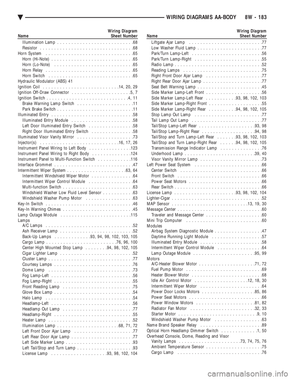
Wiring Diagram
Name Sheet Number
Illumination Lamp ...........................68
Resistor .................................68
Horn System ...............................65
Horn (Hi-Note) .............................65
Horn (Lo-Note) ............................65
Horn Relay ...............................65
Horn Switch ..............................65
Hydraulic Modulator (ABS) 41
Ignition Coil .......................... .14, 20, 29
Ignition Off-Draw Connector .....................5,7
Ignition Switch .............................4,11
Brake Warning Lamp Switch ....................11
Park Brake Switch ...........................11
Illuminated Entry .............................58
Illuminated Entry Module ......................58
Left Door Illuminated Entry Switch ................58
Right Door Illuminated Entry Switch ...............58
Illuminated Visor Vanity Mirror ....................73
Injector(s) ........................... .16, 17, 26
Instrument Panel Wiring to Left Body ...............123
Instrument Panel Wiring to Right Body ..............124
Instrument Panel to Multi-Function Switch ............116
Interface Grommet ............................47
Intermittent Wiper System .................... .63, 64
Intermittent Windshield Wiper Motor ...............64
Intermittent Wiper Control Module ................64
Multi-function Switch .........................63
Windshield Washer Low Fluid Level Sensor ...........63
Windshield Washer Pump Motor .................63
Key-In Switch ...............................46
Key-In Warning Chimes .........................45
Lamp Outage Module ........................ .115
Lamps A/C Lamps ...............................52
Ash Receiver Lamp ..........................52
Back-Up Lamps ............ .93, 94, 98, 102, 103, 105
Cargo Lamp ........................ .76, 96, 100
Center High Mounted Stop Lamp ........94, 98, 102, 105
Cigar Lighter Lamp ..........................52
Cluster Lamp ..............................77
Courtesy Lamps ............................76
Dome Lamp ..............................73
Fog Lamp-Left .............................56
Fog Lamp-Right ............................55
Front Reading Lamp .........................75
Glove Box Lamp ............................54
Halo Lamp ...............................54
Headlamp-Left .............................56
Headlamp Out Lamp .........................77
Headlamp-Right ............................55
Heater Lamp ..............................52
Illumination Lamp ..................... .68, 71, 72
Left Front Door Ajar Lamp .....................77
Left Rear Door Ajar Lamp ......................77
Left Side Marker Lamp ........................93
Left Tail/Stop and Turn Lamp ....................93
License Lamp ................... .93, 98, 102, 104Wiring Diagram
Name Sheet Number
Liftgate Ajar Lamp ..........................77
Low Washer Fluid Lamp .......................77
Park/Turn Lamp-Left .........................56
Park/Turn Lamp-Right ........................55
Radio Lamp ...............................52
Reading Lamps ............................75
Right Front Door Ajar Lamp ....................77
Right Rear Door Ajar Lamp .....................77
Seat Belt Warning Lamp .......................45
Side Marker Lamp-Left Front ....................56
Side Marker Lamp-Left Rear ...........93, 98, 102, 103
Side Marker Lamp-Right Front ...................55
Side Marker Lamp-Right Rear ..........94, 98, 102, 105
Stop Lamp Out Lamp ........................77
Tail Lamp Out Lamp .........................77
Tail/Stop Lamp-Left Rear ................... .93, 98
Tail/Stop Lamp-Right Rear .................. .94, 98
Tail/Stop and Turn Lamp-Left Rear .......93, 98, 102, 103
Tail/Stop and Turn Lamp-Right Rear ......94, 98, 102, 105
Transmission Range Indicator Lamp ...............76
Underhood Lamp ........................ .39, 40
Visor Vanity Mirror Lamp ......................73
Left Power Seat System ........................66
Center Switch .............................66
Front Switch ..............................66
Power Seat Motors ..........................66
Rear Switch ...............................66
License Lamp ..................... .93, 98, 102, 104
Lighter-Cigar ................................52
MAP Sensor .......................... .13, 19, 30
Message Center ..............................60
Traveler and Message Center ....................60
Mini Trip Computer ...........................60
Modules Airbag System Diagnostic Module .................47
Daytime Running Light Module ..................57
Illuminated Entry Module ......................58
Intermittent Wiper Control Module ................64
Lamp Outage Module ..................... .95, 99
Motors A/C-Heater Blower Motor ................... .71, 72
Fuel Pump Motor ...........................69
Heater Blower Motor .........................68
Idle Air Control Motor .................. .12, 18, 30
Intermittent Wiper Motor ......................64
Power Door Locks Motors .................. .85, 86
Power Seat Motors ..........................66
Power Window Motors .................... .81, 82
Radiator Fan Motor ...................... .32, 33
Starter Motor ............................9,10
Windshield Washer Pump Motor .................63
Name Brand Speaker Relay ......................89
Optical Horn Headlamp Dimmer Switch .............1,50
Overhead Console, Dome, Reading and Visor Vanity Lamps ..................... .73, 74, 75, 76
Ambient Temperature Sensor ....................75
Cargo Lamp ..............................76
Ä WIRING DIAGRAMS AA-BODY 8W - 183