1993 CHEVROLET PLYMOUTH ACCLAIM radiator
[x] Cancel search: radiatorPage 364 of 2438

sends the message to the Engine Controller. The En-
gine Controller turns on the fan through the fan re-
lay. See Wiring Diagrams Manual for circuity and
diagnostics provided.Switching through the Engine Controller provides
fan control for the following conditions.
² The fan will not run during cranking until the en-
gine starts no matter what the coolant temperature
is.
² Fan will run when the air conditioning clutch is
engaged and low pressure cutout switch is closed.
² For 4 cylinder application the fan will run at ve-
hicle speeds above about 40 mph only if coolant tem-
perature reaches 110ÉC (230ÉF). It will turn off when
the temperature drops to 104ÉC (220ÉF). At speeds
below 40 mph the fan switches on at 102ÉC (215ÉF)
and off at 93ÉC (200ÉF).
² This is to help prevent steaming. The fan will run
only below 16ÉC (60ÉF) ambient. Between 38ÉC
(100ÉF) to 97ÉC (195ÉF) coolant temperature, at idle
and then only for three minutes.
RADIATOR FAN CONTROLÐAC/AY BODY V-6 ONLY
For this application, fan control is accomplished
based on coolant temperature, and on A/C head pres-
sure. These vehicles receive the variable displace-
ment compressor. The fan will go on when;
² Coolant temperature reaches 102ÉC (215ÉF) and off
at 93.4ÉC (200ÉF) regardless of vehicle speed.
² When the head pressure reaches 1516.9 kPa (220
psi) and turn off when the pressure reaches 1103 kPa
(160 psi).
TEMPERATURE GAUGE INDICATION
At idle the temperature gauge will rise slowly to
about 5/8 gauge travel. The fan will come on and the
gauge will drop to about 1/2 gauge travel, this is nor-
mal.
ELECTRIC FAN MOTOR
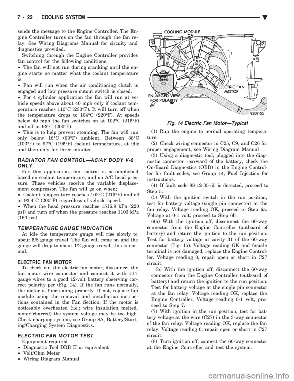
To check out the electric fan motor, disconnect the
fan motor wire connector and connect it with #14
gauge wires to a good 12-volt battery observing cor-
rect polarity per (Fig. 14). If the fan runs normally,
the motor is functioning properly. If not, replace fan
module using the removal and installation instruc-
tions contained in the Fan Section. If the motor is
noticeably overheated (i.e.; wire insulation melted,
motor charred) the system voltage may be too high.
Check charging system, see Group 8A, Battery/Start-
ing/Charging System Diagnostics.
ELECTRIC FAN MOTOR TEST
Equipment required
² Diagnostic Tool DRB II or equivalent
² Volt/Ohm Meter
² Wiring Diagram Manual (1) Run the engine to normal operating tempera-
ture. (2) Check wiring connector in C25, C9, and C26 for
proper engagement, see Wiring Diagram Manual (3) Using a diagnostic tool, plugged into the diag-
nostic connector rearward of the battery, check the
On-Board Diagnostics (OBD) in the Engine Control-
ler for fault codes, see Group 14, Fuel Injection for
instructions. (4) If fault code 88-12-35-55 is detected, proceed to
Step 5. (5) With the ignition switch in the run position,
test for battery voltage (single pin connector) at the
fan relay. Voltage reading OK, proceed to Step 6a.
Voltage at 0-1 volt, proceed to Step 6b. 6(a) With the ignition off, disconnect the 60-way
connector from the Engine Controller (outboard of
battery) and return the ignition to the run position.
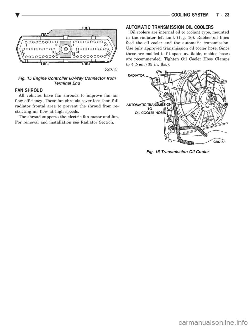
Test for battery voltage at cavity 31 of the 60-way
connector (Fig. 15). Voltage reading OK and female
terminal is not damaged, replace the Engine Control-
ler. Voltage reading 0, repair open or short in C27
circuit. (b) With the ignition off, disconnect the 60-way
connector from the Engine Controller (outboard of
battery) and return the ignition to the run position.
Test for battery voltage at the single pin connector
at the fan relay. Voltage reading OK, replace the
Engine Controller. Voltage reading 0-1 volt, pro-
ceed to Step 7.
(7) With ignition in the run position, test for bat-
tery voltage at the wire (C27) in the 3-way connector
of the fan relay. Voltage reading OK, replace the fan
relay. Voltage reading 0, repair open or short in C27
circuit. (8) Turn ignition off, connect the 60-way connector
at the Engine Controller and test the system.
Fig. 14 Electric Fan MotorÐTypical
7 - 22 COOLING SYSTEM Ä
Page 365 of 2438

FAN SHROUD
All vehicles have fan shrouds to improve fan air
flow efficiency. These fan shrouds cover less than full
radiator frontal area to prevent the shroud from re-
stricting air flow at high speeds. The shroud supports the electric fan motor and fan.
For removal and installation see Radiator Section.
AUTOMATIC TRANSMISSION OIL COOLERS
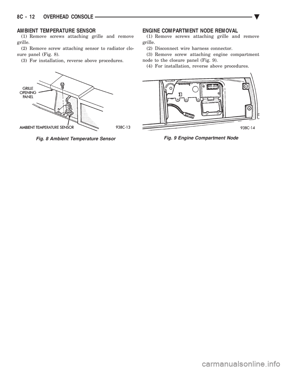
Oil coolers are internal oil to coolant type, mounted
in the radiator left tank (Fig. 16). Rubber oil lines
feed the oil cooler and the automatic transmission.
Use only approved transmission oil cooler hose. Since
these are molded to fit space available, molded hoses
are recommended. Tighten Oil Cooler Hose Clamps
to4N Im (35 in. lbs.).
Fig. 15 Engine Controller 60-Way Connector from
Terminal End
Fig. 16 Transmission Oil Cooler
Ä COOLING SYSTEM 7 - 23
Page 370 of 2438

ENGINE BLOCK HEATER
DESCRIPTION AND OPERATION
On all models an engine block heater is available as
an optional accessory. The heater, operated by ordinary
house current (110 Volt A.C.) through a power cord and
connector behind the radiator grille, provides easier
engine starting and faster warm-up when vehicle is
operated in areas having extremely low temperatures.
The heater is mounted in a core hole (in place of a core
hole plug) in the engine block, with the heating ele-
ment immersed in coolant (Fig. 9). The power cord must be secured in its retainer
clips, and not positioned so it could contact link-
ages or exhaust manifolds and become damaged. If unit does not operate, trouble can be in either the
power cord or the heater element. Test power cord for
continuity with a 110-volt voltmeter or 110-volt test
light; test heater element continuity with an ohmmeter
or 12-volt test light.
REMOVAL
(1) Drain coolant from radiator and cylinder block.
Refer to Cooling System Drain, Clean, Flush and Re-
fill of this section for procedure. (2) Detach power cord plug from heater.
(3) Loosen screw in center of heater. Remove
heater assembly.
INSTALLATION
(1) Thoroughly clean core hole and heater seat.
(2) Insert heater assembly with element loop posi-
tioned upward.
(3) With heater seated, tighten center screw se-
curely to assure a positive seal. (4) Fill cooling system with coolant to the proper
level, vent air, and inspect for leaks. Pressurize sys-
tem with Radiator Pressure Tool before looking for
leaks.
Fig. 9 Engine Block Heater
7 - 28 COOLING SYSTEM Ä
Page 417 of 2438

OVERHEAD CONSOLE
CONTENTS
page page
AA BODY .............................. 1
AC AND AY BODY ....................... 6 AG AND AJ BODIES
.................... 13
AP BODY ............................. 21
GENERAL INFORMATION AA BODY
INDEX
page page
Ambient Temperature Sensor ................ 6
Compass Calibration ....................... 2
Compass Diagnostics ...................... 5
Compass Module Replacement ............... 6
Demagnetizing Procedure ................... 4 Map Reading Lamps
....................... 1
Overhead Console Replacement .............. 5
Self-Diagnostic Test ....................... 5
Thermometer and Compass Operation ......... 1
Variance ................................ 2
MAP READING LAMPS
The map reading and rear passenger lamps are
turned on and off by pressing their individual switch
marked LAMP. These same lamps also serve as cour-
tesy lamps whenever a door is opened, the illumi-
nated entry system is activated, or the headlamp
switch is turned fully clockwise.
LAMP REPLACEMENT
(1) Remove lens by inserting a large paper clip or
wire, with a hook on the end, into the hole in the
lens and pull downward (Fig. 1).
(2) Remove lamp by pulling firmly toward front of
vehicle. (3) Install new lamp by pushing firmly into recep-
tacle. (4) Snap lens into position taking care to orient
the tabs on the lens with the slots in the housing and
snap into position.
LAMP TEST
(1) Close vehicle doors.
(2) Press each lamp switch button (Fig.2). Right
hand button should light passenger side lamp and
left hand button should light drivers side lamp front
or rear. (3) If any of the lamps fail to illuminate, open ve-
hicle doors: (a) If lamp does not illuminate check for a
burned out lamp. If lamp is OK, check fuse and
wire connectors. (b) If lamp illuminates when doors are open
check switch.
THERMOMETER AND COMPASS OPERATION
The ignition switch must be in the ON or ACCES-
SORY position before the temperature and compass
reading can be displayed. The Comp/Temp switch, lo-
cated left of the display module, turns the display on
and off. The US/Metric switch, located right of the dis-
play, changes the temperature reading from Fahrenheit
to Celsius. Should the compass blank out and the CAL
symbol only light, demagnetizing may be necessary.
The compass is a flux-gate system which, is inte-
gral to the console. The temperature readout is con-
nected to a thermistor sensor which, located on the
front lower radiator closure panel.Fig. 1 Overhead Console Lens Removal
Ä OVERHEAD CONSOLE 8C - 1
Page 428 of 2438

AMBIENT TEMPERATURE SENSOR
(1) Remove screws attaching grille and remove
grille. (2) Remove screw attaching sensor to radiator clo-
sure panel (Fig. 8). (3) For installation, reverse above procedures.
ENGINE COMPARTMENT NODE REMOVAL
(1) Remove screws attaching grille and remove
grille. (2) Disconnect wire harness connector.
(3) Remove screw attaching engine compartment
node to the closure panel (Fig. 9). (4) For installation, reverse above procedures.
Fig. 8 Ambient Temperature SensorFig. 9 Engine Compartment Node
8C - 12 OVERHEAD CONSOLE Ä
Page 436 of 2438

OVERHEAD CONSOLE REPLACEMENT
(1) Unscrew the mounting screw in sun glass bin
compartment (Fig. 8).
(2) Slide console forward toward windshield until
the console unhooks from roof bracket. (3) Disconnect wire harness from console.
(4) For installation reverse above procedures.
COMPASS MODULE REPLACEMENT
(1) Remove overhead console.
(2) Using a small screwdriver, release the 2 snaps
at rear of compass module (Fig. 9).
(3) After releasing the 2 snaps, slide compass mod-
ule rearward until free of mounting bar. (4) For installation reverse above procedures.
ELECTRONIC VEHICLE INFORMATION CENTER
(EVIC) REMOVAL
(1) Use a straight edge tool to pry out one end of
the EVIC center and continue to disengage six clips
along the length of the message center. (2) Remove the EVIC center and disconnect the
wiring. (3) For installation reverse the above procedures.
AMBIENT TEMPERATURE SENSOR REMOVAL
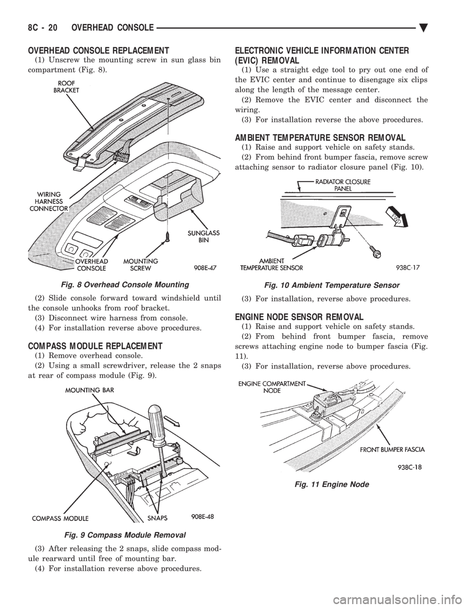
(1) Raise and support vehicle on safety stands.
(2) From behind front bumper fascia, remove screw
attaching sensor to radiator closure panel (Fig. 10).
(3) For installation, reverse above procedures.
ENGINE NODE SENSOR REMOVAL
(1) Raise and support vehicle on safety stands.
(2) From behind front bumper fascia, remove
screws attaching engine node to bumper fascia (Fig.
11). (3) For installation, reverse above procedures.
Fig. 8 Overhead Console Mounting
Fig. 9 Compass Module Removal
Fig. 10 Ambient Temperature Sensor
Fig. 11 Engine Node
8C - 20 OVERHEAD CONSOLE Ä
Page 441 of 2438

Test 3 (d3) performs a walking segment test which,
sequentially puts different directions and numbers on
the display. If any segment fails, replace the compass
module.
OVERHEAD CONSOLE REPLACEMENT
(1) Unscrew the mounting screw in sun glass bin
compartment (Fig. 6).
(2) Slide console forward toward windshield until
the console unhooks from roof bracket. (3) Disconnect wire harness from console.
(4) For installation reverse above procedures.
COMPASS MODULE REPLACEMENT
(1) Remove overhead console (Fig 6).
(2) Using a small screwdriver, release the 2 snaps
at rear of compass module (Fig. 7). (3) After releasing the 2 snaps, slide compass mod-
ule rearward until free of mounting bar. (4) For installation reverse above procedures.
AMBIENT TEMPERATURE SENSOR REMOVAL
(1) Raise and support vehicle on safety stands.
(2) Behind front bumper fascia, remove screw at-
taching sensor to radiator closure panel (Fig. 8). (3) For installation, reverse above procedures.
Fig. 6 Overhead Console Mounting
Fig. 7 Compass Module Removal
Fig. 8 Ambient Temperature Sensor
Ä
OVERHEAD CONSOLE 8C - 25
Page 450 of 2438

to the thermostat housing (Fig. 20). The sensor pro-
vides an input voltage to the powertrain control mod-
ule (PCM). The sensor is a variable resistance
(thermistor) with a range of -40ÉF to 265ÉF. As cool-
ant temperature varies, the sensors resistance
changes, resulting in a different input voltage to the
PCM. The PCM contains different spark advance sched-
ules for cold and warm engine operation. The sched-
ules reduce engine emissions and improve
driveability. Because spark advance changes at dif-
ferent engine operating temperatures during warm-
up, all spark advance testing should be done with the
engine fully warmed. The PCM demands slightly richer air-fuel mixtures
and higher idle speeds until the engine reaches nor-
mal operating temperature. The coolant sensor input is also used for radiator
fan control.
MANIFOLD ABSOLUTE PRESSURE (MAP) SENSOR
The MAP sensor reacts to absolute pressure in the
intake manifold and provides an input voltage to the
powertrain control module (PCM). As engine load
changes, manifold pressure varies. The changes in
engine load causes the MAP sensors output voltage
to change. The change in MAP sensor output voltage
results in a different input voltage to the PCM. The input voltage level supplies the PCM with in-
formation relating to ambient barometric pressure
during engine start-up (cranking) and engine load
while its operating. The PCM uses this input along
with inputs from other sensors to adjust air-fuel mix-
ture. On 2.2L TBI, 2.5L TBI and 2.5L MPI (flexible fuel
AA-body) engines, the MAP sensor is mounted to the
dash panel (Fig. 21 or Fig. 22). On 3.0L engines, the
sensor is mounted to a bracket across from the dis-
tributor (Fig. 23). The sensor is connected to the
throttle body or intake manifold with a vacuum hose
and to the PCM electrically.
AUTO SHUTDOWN (ASD) RELAY AND FUEL PUMP
RELAY
The powertrain control module (PCM) operates the
auto shutdown (ASD) relay and fuel pump relay
through one ground path. The PCM operates the re-
lays by switching the ground path on and off. Both
relays turn on and off at the same time. The ASD relay connects battery voltage to the fuel
injector and ignition coil. The fuel pump relay con-
nects battery voltage to the fuel pump and oxygen
sensor heating element. The PCM turns the ground path off when the igni-
tion switch is in the Off position. Both relays are off.
When the ignition switch is in the On or Crank po-
sition, the PCM monitors the distributor pick-up sig-
Fig. 19 Coolant Temperature SensorÐ2.2L TBI, 2.5L TBI and 2.5L MPI Engines
Fig. 20 Coolant Temperature SensorÐ3.0L Engines
Fig. 21 MAP SensorÐ2.2L and 2.5L TBI Engines
8D - 8 IGNITION SYSTEMS Ä