1993 CHEVROLET PLYMOUTH ACCLAIM check engine
[x] Cancel search: check enginePage 2314 of 2438
backed off, immediately point the end of hose toward
floor, as possibly trapped refrigerant in the hose will
be released.(e) Install service port cap.
DISCHARGE (HIGH PRESSURE) GAUGE CONNECTION (1) Remove the service port cap from the 1/4 in.
service port. (2) Check all valves on the equipment being used to
verify they are closed. (3) Inspect the hose gasket in the service port con-
nector at the end of the (RED) hose. If the gasket is
flawed, replace it. (4) Use a suitable (3/8 in. male to 1/4 in. female)
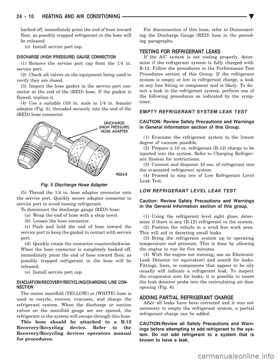
adapter (Fig. 5), threaded securely into the end of the
(RED) hose connector.
(5) Thread the 1/4 in. hose adapter connector onto
the service port. Quickly secure adapter connector to
service port to avoid loosing refrigerant. To disconnect the discharge gauge (RED) hose:(a) Wrap the end of hose with a shop towel.
(b) Loosen the hose connector.
(c) Push and hold the end of hose toward the
service port to keep the gasket in contact with service
port. (d) Quickly rotate the connector counterclockwise.
When the hose connector is completely backed off,
immediately point the end of hose toward floor, as
possibly trapped refrigerant in the hose will be
released. (e) Install service port cap.
EVACUATION/RECOVERY/RECYCLING/CHARGING LINE CON-
NECTION
The center manifold (YELLOW) or (WHITE) hose is
used to recycle, recover, evacuate, and charge the
refrigerant system. When the discharge or suction
valves on the manifold gauge set are opened, the
refrigerant in the system will escape through this hose. This hose should be attached to a R-12
Recovery/Recycling device. Refer to the
Recovery/Recycling devices operators manual
for procedures. For disconnection of this hose, refer to Disconnect-
ing the Discharge Gauge (RED) hose in the preced-
ing paragraphs.
TESTING FOR REFRIGERANT LEAKS
If the A/C system is not cooling properly, deter-
mine if the refrigerant system is fully charged with
R-12. Follow the procedures in the Performance Test
Procedures section of this Group. If the refrigerant
system is empty or low in refrigerant charge, a leak
at any line fitting or component seal is likely. To de-
tect a leak in the refrigerant system, perform one of
the following procedures as indicated by the symp-
toms.
EMPTY REFRIGERANT SYSTEM LEAK TEST
CAUTION: Review Safety Precautions and Warnings
in General Information section of this Group.
(1) Evacuate the refrigerant system to the lowest
degree of vacuum possible. (2) Prepare a 10 oz. refrigerant (R-12) charge to be
injected into the system. Refer to Charging Refriger-
ant System for instructions. (3) Connect and dispense 10 ozs. of refrigerant into
the evacuated refrigerant system. (4) Proceed to step two of Low Refrigerant Level
Leak Test.
LOW REFRIGERANT LEVEL LEAK TEST
Caution: Review Safety Precautions and Warnings
in the General Information section of this group.
(1) Using the refrigerant level sight glass, deter-
mine if there is any (R-12) refrigerant in the system. (2) Position the vehicle in a wind free work area.
This will aid in detecting small leaks. (3) Bring the refrigerant system up to operating
temperature and pressure. This is done by allowing
the engine to run for five minutes. (4) With the engine not running, use an Electronic
Leak Detector (or equivalent) and search for leaks.
Fittings, lines, or components that appear to be oily
usually will indicate a refrigerant leak. To inspect
the evaporator core for leaks, it is possible to insert
the leak detector probe into the recirculating air door
opening (Fig. 6).
ADDING PARTIAL REFRIGERANT CHARGE
After all leaks have been corrected and it was not
necessary to empty the refrigerant system, a partial
refrigerant charge can be added.
CAUTION:Review all Safety Precautions and Warn-
ings before attempting to add refrigerant to the sys-
tem. Do not add refrigerant to a system that is
known to have a leak.
Fig. 5 Discharge Hose Adapter
24 - 10 HEATING AND AIR CONDITIONING Ä
Page 2316 of 2438
WARNING: REVIEW SAFETY PRECAUTIONS AND
WARNINGS BEFORE CHARGING THE REFRIGER-
ANT SYSTEM.
After the system has been tested for leaks and
evacuated, a refrigerant charge can be injected into
the system. (1) Connect manifold gauge set.
(2) Measure refrigerant (refer to capacities) and
heat to 52ÉC (125ÉF) with the charging station. Refer
to the instructions provided with the equipment be-
ing used.
REFRIGERANT CAPACITIES:
² Without Rear A/C = 907 g (32 oz.)
² With Rear A/C = 1219 g (43 oz.)
(3) Open the suction and discharge valves. Open
the charge valve to allow the heated refrigerant to
flow into the system. When the transfer of refriger-
ant has stopped, close the suction and discharge
valve. (4) If all of the refrigerant charge did not transfer
from the dispensing device, start engine and hold at
idle (1400 rpm). Set the A/C control to A/C, low
blower speed, and open windows. If the A/C compres-
sor does not engage, test the compressor clutch con-
trol circuit and correct any failure. Refer to Group
8W, Wiring Diagrams. (5) Open the suction valve to allow the remaining
refrigerant to transfer to the system.
WARNING: TAKE CARE NOT TO OPEN THE DIS-
CHARGE (HIGH-PRESSURE) VALVE AT THIS TIME.
(6) Close all valves and test the A/C system perfor-
mance. Refer to Heater and A/C Performance Tests
in this Group. (7) Disconnect the charging station or manifold
gauge set. Install the service port caps.
OIL LEVEL
It is important to have the correct amount of oil in
the A/C system to ensure proper lubrication of the
compressor. Too little oil will result in damage to the
compressor. Too much oil will reduce the cooling ca-
pacity of the system. The oil used in the compressor is a 500 SUS viscos-
ity, wax-free refrigerant oil. Only refrigerant oil of
the same type should be used to service the system.
Do not use any other oil. The oil container should be
kept tightly capped until it is ready for use, and then
tightly capped after use to prevent contamination
from dirt and moisture. Refrigerant oil will quickly
absorb any moisture it comes in contact with. It will not be necessary to check oil level in the
compressor or to add oil unless there has been an oil
loss. This may be due to a ruptured line, shaft seal leakage, leakage from the evaporator, condenser
leak, filter drier or loss of refrigerant due to a colli-
sion. Oil loss at a the leak point will be evident by
the presence of a wet, shiny surface around the leak.
REFRIGERANT OIL LEVEL CHECK
When an A/C system is assembled at the factory,
all components (except the compressor) are refriger-
ant oil free. After the system has been charged with
R-12 and operated, the oil in the compressor is dis-
persed through the lines and components. The evap-
orator, condenser, and filter-drier will retain a
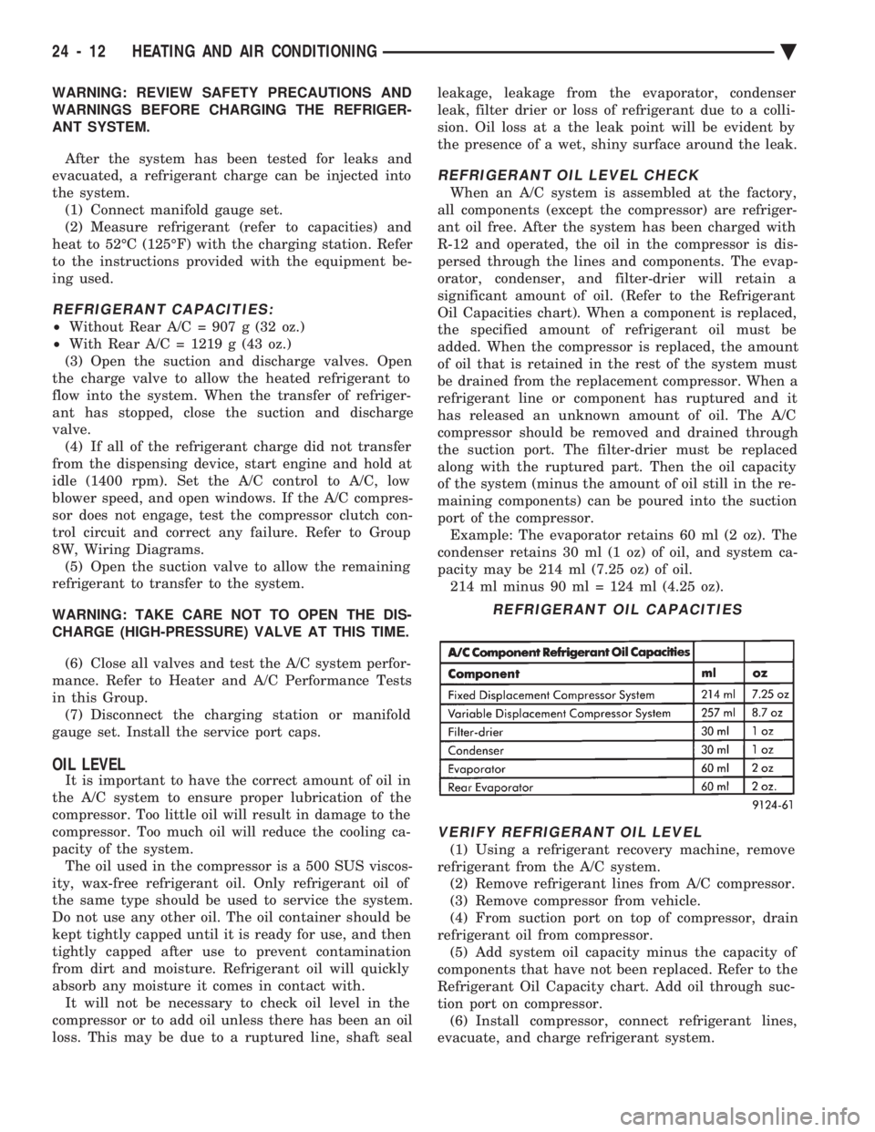
significant amount of oil. (Refer to the Refrigerant
Oil Capacities chart). When a component is replaced,
the specified amount of refrigerant oil must be
added. When the compressor is replaced, the amount
of oil that is retained in the rest of the system must
be drained from the replacement compressor. When a
refrigerant line or component has ruptured and it
has released an unknown amount of oil. The A/C
compressor should be removed and drained through
the suction port. The filter-drier must be replaced
along with the ruptured part. Then the oil capacity
of the system (minus the amount of oil still in the re-
maining components) can be poured into the suction
port of the compressor. Example: The evaporator retains 60 ml (2 oz). The
condenser retains 30 ml (1 oz) of oil, and system ca-
pacity may be 214 ml (7.25 oz) of oil. 214 ml minus 90 ml = 124 ml (4.25 oz).
VERIFY REFRIGERANT OIL LEVEL
(1) Using a refrigerant recovery machine, remove
refrigerant from the A/C system. (2) Remove refrigerant lines from A/C compressor.
(3) Remove compressor from vehicle.
(4) From suction port on top of compressor, drain
refrigerant oil from compressor. (5) Add system oil capacity minus the capacity of
components that have not been replaced. Refer to the
Refrigerant Oil Capacity chart. Add oil through suc-
tion port on compressor. (6) Install compressor, connect refrigerant lines,
evacuate, and charge refrigerant system.
REFRIGERANT OIL CAPACITIES
24 - 12 HEATING AND AIR CONDITIONING Ä
Page 2317 of 2438
VARIABLE DISPLACEMENT COMPRESSORÐMODEL 6C17 INDEX
page page
Clutch Coil Tests ......................... 17
Compressor ............................. 17
Compressor Clutch Inoperative .............. 13
Compressor Clutch/Coil Assembly ............ 19
Compressor Diagnosis ..................... 13
Compressor Front Shaft Seal ............... 20 Compressor High Pressure Cut-Out Switch
..... 21
Compressor High Pressure Relief Valve (HPR) . . 22
Compressor Identification ................... 13
Compressor Main or Sub Control Valves ....... 22
Compressor Noise ........................ 13
General Information ....................... 13
GENERAL INFORMATION
The Variable Displacement Compressor (VDC) pro-
vides maximum A/C performance under most condi-
tions. It is designed to operate continuously without
any cycling of the compressor clutch. The compressor
has a variable angle wobble plate with six axially
oriented cylinders. During vehicle A/C system operation, the compres-
sor will change its displacement to match the vehi-
cles A/C cooling demands. When the A/C system
needs more cooling capacity, the compressor will in-
crease its pumping capacity. This is done by increas-
ing the wobble plate angle to increase the piston
stroke. When the A/C system cooling demand is low,
the compressor will decrease its pumping capacity by
reducing the piston pumping stroke. The low cooling
capacity will prevent evaporator from freezing.
COMPRESSOR IDENTIFICATION
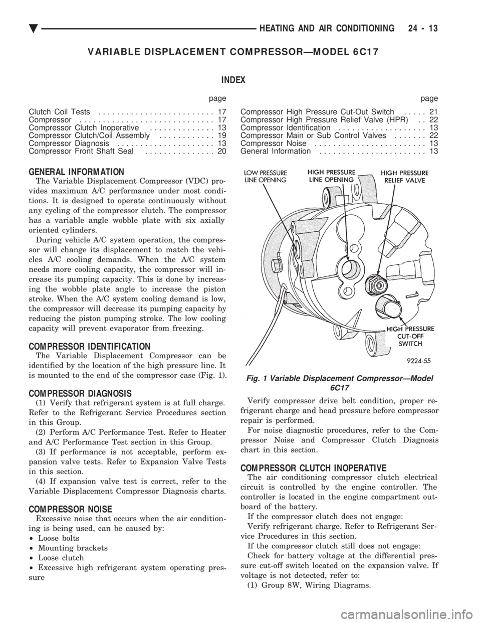
The Variable Displacement Compressor can be
identified by the location of the high pressure line. It
is mounted to the end of the compressor case (Fig. 1).
COMPRESSOR DIAGNOSIS
(1) Verify that refrigerant system is at full charge.
Refer to the Refrigerant Service Procedures section
in this Group. (2) Perform A/C Performance Test. Refer to Heater
and A/C Performance Test section in this Group. (3) If performance is not acceptable, perform ex-
pansion valve tests. Refer to Expansion Valve Tests
in this section. (4) If expansion valve test is correct, refer to the
Variable Displacement Compressor Diagnosis charts.
COMPRESSOR NOISE
Excessive noise that occurs when the air condition-
ing is being used, can be caused by:
² Loose bolts
² Mounting brackets
² Loose clutch
² Excessive high refrigerant system operating pres-
sure Verify compressor drive belt condition, proper re-
frigerant charge and head pressure before compressor
repair is performed. For noise diagnostic procedures, refer to the Com-
pressor Noise and Compressor Clutch Diagnosis
chart in this section.
COMPRESSOR CLUTCH INOPERATIVE
The air conditioning compressor clutch electrical
circuit is controlled by the engine controller. The
controller is located in the engine compartment out-
board of the battery. If the compressor clutch does not engage:
Verify refrigerant charge. Refer to Refrigerant Ser-
vice Procedures in this section. If the compressor clutch still does not engage:
Check for battery voltage at the differential pres-
sure cut-off switch located on the expansion valve. If
voltage is not detected, refer to: (1) Group 8W, Wiring Diagrams.
Fig. 1 Variable Displacement CompressorÐModel 6C17
Ä HEATING AND AIR CONDITIONING 24 - 13
Page 2321 of 2438
(2) The appropriate Powertrain Diagnostic Proce-
dures Manual for diagnostic information. (3) The Compressor Clutch DiagnosisÐVariable
Displacement Compressor chart in this section. (4) On 2.2 L Turbo III engines, check for battery
voltage at the Thermal Limiter Switch located on the
compressor. If voltage is found at the cut-off and/or thermal
limiter switch, reconnect switch. Then check for bat-
tery voltage between the compressor clutch connector
terminals. If voltage is detected, perform A/C Clutch Coil
Tests. Refer to Clutch Coil Tests in this section.
CLUTCH COIL TESTS
(1) Verify battery state of charge. (Test indicator
in battery should be green). (2) Connect an ammeter (0-10 ampere scale) in se-
ries with the clutch coil terminal. Use a volt meter
(0-20 volt scale) with clip leads measuring voltage
across the battery and A/C clutch. (3) With A/C control in A/C mode and blower at
low speed, start the engine and run at normal idle. (4) The A/C clutch should engage immediately and
the clutch voltage should be within two volts of the
battery voltage. If the A/C clutch does not engage,
test the fusible link. (5) The A/C clutch coil is acceptable if the current
draw is 2.0 to 3.7 amperes at 11.5-12.5 volts at clutch
coil. This is with the work area temperature at 21ÉC
(70ÉF). If voltage is more than 12.5 volts, add electri-
cal loads by turning on electrical accessories until
voltage reads below 12.5 volts. If coil current reads zero, the coil is open and
should be replaced. If the ammeter reading is 4 am-
peres or more, the coil is shorted and should be re-
placed. If the coil voltage is not within two volts of
the battery voltage, test clutch coil feed circuit for
excessive voltage drop.
COMPRESSOR
The A/C compressor may be removed and posi-
tioned without discharging the refrigerant system.
Discharging is not necessary if removing the A/C
compressor clutch/coil assembly, engine, cylinder
head, or generator.
WARNING: REFRIGERANT PRESSURES REMAIN HIGH
EVEN THOUGH THE ENGINE MAY BE TURNED OFF.
BEFORE REMOVING A FULLY CHARGED COMPRES-
SOR, REVIEW THE SAFETY PRECAUTIONS AND
WARNINGS SECTION IN THIS GROUP. DO NOT TWIST
OR KINK THE REFRIGERANT LINES WHEN REMOV-
ING A FULLY CHARGED COMPRESSOR. SAFETY
GLASSES MUST BE WORN.
REMOVAL AND INSTALLATION
(1) Disconnect NEGATIVE battery cable.
(2) Loosen and remove drive belts (Refer to Group
7, Cooling System) and disconnect compressor clutch
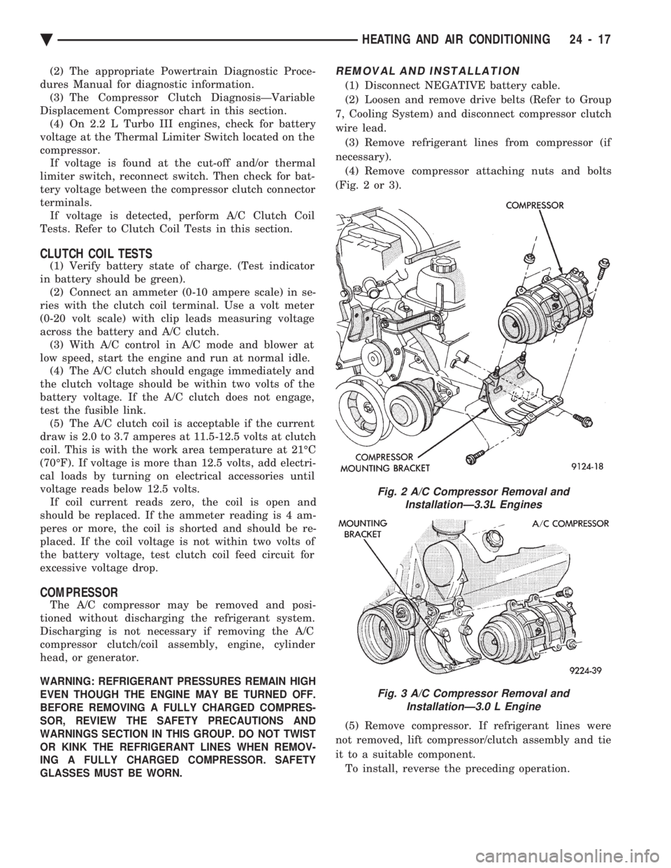
wire lead. (3) Remove refrigerant lines from compressor (if
necessary). (4) Remove compressor attaching nuts and bolts
(Fig. 2 or 3).
(5) Remove compressor. If refrigerant lines were
not removed, lift compressor/clutch assembly and tie
it to a suitable component. To install, reverse the preceding operation.
Fig. 2 A/C Compressor Removal and InstallationÐ3.3L Engines
Fig. 3 A/C Compressor Removal and InstallationÐ3.0 L Engine
Ä HEATING AND AIR CONDITIONING 24 - 17
Page 2328 of 2438
FIXED DISPLACEMENT COMPRESSORÐMODEL 10PA17 INDEX
page page
Compressor ............................. 24
Compressor Clutch/Coil Assembly ............ 24
Compressor Front Shaft Seal ............... 27 Compressor High-Pressure Relief Valve
....... 30
Refrigerant System Diagnosis ............... 30
COMPRESSOR
COMPRESSOR NOISE
Excessive noise that occurs when the air condition-
ing is being used, can be caused by:
² Loose bolts
² Mounting brackets
² Loose clutch
² Excessive high refrigerant system operating pres-
sure Verify compressor drive belt condition, proper re-
frigerant charge and head pressure before compressor
repair is performed. For noise diagnostic procedures, refer to the Com-
pressor Noise and Compressor Clutch Diagnosis
chart in this section.
REMOVAL AND INSTALLATION
The A/C compressor may be removed and posi-
tioned without discharging the refrigerant system.
Discharging is not necessary if removing the A/C
compressor clutch/coil assembly, engine, cylinder
head, or generator.
WARNING: REFRIGERANT PRESSURES REMAIN
HIGH EVEN THOUGH THE ENGINE MAY BE
TURNED OFF. BEFORE REMOVING A FULLY
CHARGED COMPRESSOR, REVIEW THE SAFETY
PRECAUTIONS AND WARNINGS SECTION IN THIS
GROUP. DO NOT TWIST OR KINK THE REFRIGER-
ANT LINES WHEN REMOVING A FULLY CHARGED
COMPRESSOR. SAFETY GLASSES MUST BE
WORN.
(1) Disconnect Negative battery cable.
(2) Loosen and remove drive belts (refer to Group
7, Cooling System) and disconnect compressor clutch
wire lead. (3) Remove refrigerant lines from compressor (if
necessary). (4) Remove compressor attaching nuts and bolts.
(5) Remove compressor. If refrigerant lines were
not removed, lift compressor/clutch assembly and tie
it to a suitable component. To install, reverse the preceding operation. If nec-
essary, refer to Charging Refrigerant System in the
Refrigerant Service Procedures section.
COMPRESSOR CLUTCH/COIL ASSEMBLY
CLUTCH INOPERATIVE
The air conditioning compressor clutch electrical
circuit is controlled by the engine controller. The
controller is located in the engine compartment out-
board of the battery. If the compressor clutch does not engage:
Verify refrigerant charge.
If the compressor clutch still does not engage check
for battery voltage at the low pressure or differential
pressure cut-off switch located on the expansion
valve. If voltage is not detected, refer to:
² Group 8W, Wiring Diagrams.
² The appropriate Powertrain Diagnostic Procedures
Manual for diagnostic information. If voltage is detected at the cut-off switch, recon-
nect switch. Then check for battery voltage between
the compressor clutch connector terminals. If voltage is detected, perform A/C Clutch Coil
Tests.
CLUTCH COIL TESTS
(1) Verify battery state of charge. (Test indicator
in battery should be green). (2) Connect an ammeter (0-10 ampere scale) in se-
ries with the clutch coil terminal. Use a volt meter
(0-20 volt scale) with clip leads measuring voltage
across the battery and A/C clutch. (3) With A/C control in A/C mode and blower at
low speed, start the engine and run at normal idle. (4) The A/C clutch should engage immediately and
the clutch voltage should be within two volts of the
battery voltage. If the A/C clutch does not engage,
test the fusible link. (5) The A/C clutch coil is acceptable if the current
draw is 2.0 to 3.7 amperes at 11.5-12.5 volts at clutch
coil. This is with the work area temperature at 21ÉC
(70ÉF). If voltage is more than 12.5 volts, add electri-
cal loads by turning on electrical accessories until
voltage reads below 12.5 volts. If coil current reads zero, the coil is open and
should be replaced. If the ammeter reading is 4 am-
peres or more, the coil is shorted and should be re-
placed. If the coil voltage is not within two volts of
the battery voltage, test clutch coil feed circuit for
excessive voltage drop.
24 - 24 HEATING AND AIR CONDITIONING Ä
Page 2331 of 2438
(7) Check bearing for roughness or excessive leak-
age of grease. Replace bearing as required.
INSTALLATION
(1) Align pin in back of field coil with hole in com-
pressor end housing, and position field coil into place.
Make sure that lead wires are properly routed, and
fasten with the wire clip retaining screw. (2) Install field coil retaining snap ring with Snap
Ring Pliers (C-4574). The bevel side of the snap ring
must be outward. Also both eyelets must be to the
right or left of the pin on the compressor. Press snap
ring to make sure it is properly seated in the groove.
CAUTION: If snap ring is not fully seated it will vi-
brate out, resulting in a clutch failure and severe
damage to the front face of the compressor.
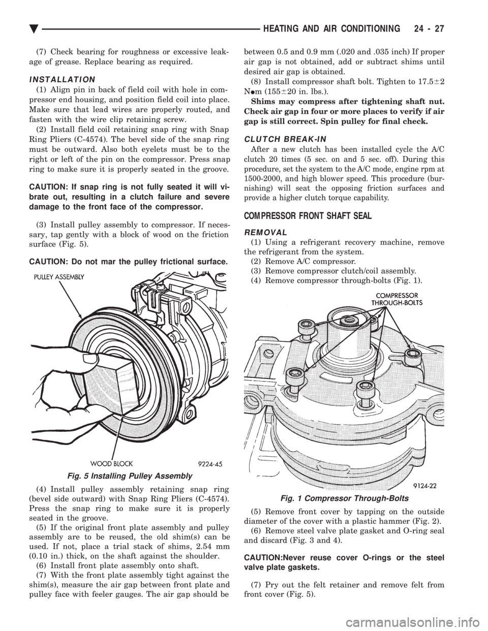
(3) Install pulley assembly to compressor. If neces-
sary, tap gently with a block of wood on the friction
surface (Fig. 5).
CAUTION: Do not mar the pulley frictional surface.
(4) Install pulley assembly retaining snap ring
(bevel side outward) with Snap Ring Pliers (C-4574).
Press the snap ring to make sure it is properly
seated in the groove. (5) If the original front plate assembly and pulley
assembly are to be reused, the old shim(s) can be
used. If not, place a trial stack of shims, 2.54 mm
(0.10 in.) thick, on the shaft against the shoulder. (6) Install front plate assembly onto shaft.
(7) With the front plate assembly tight against the
shim(s), measure the air gap between front plate and
pulley face with feeler gauges. The air gap should be between 0.5 and 0.9 mm (.020 and .035 inch) If proper
air gap is not obtained, add or subtract shims until
desired air gap is obtained.
(8) Install compressor shaft bolt. Tighten to 17.5 62
N Im (155 620 in. lbs.).
Shims may compress after tightening shaft nut.
Check air gap in four or more places to verify if air
gap is still correct. Spin pulley for final check.
CLUTCH BREAK-IN
After a new clutch has been installed cycle the A/C
clutch 20 times (5 sec. on and 5 sec. off). During this
procedure, set the system to the A/C mode, engine rpm at
1500-2000, and high blower speed. This procedure (bur-
nishing) will seat the opposing friction surfaces and
provide a higher clutch torque capability.
COMPRESSOR FRONT SHAFT SEAL
REMOVAL
(1) Using a refrigerant recovery machine, remove
the refrigerant from the system. (2) Remove A/C compressor.
(3) Remove compressor clutch/coil assembly.
(4) Remove compressor through-bolts (Fig. 1).
(5) Remove front cover by tapping on the outside
diameter of the cover with a plastic hammer (Fig. 2). (6) Remove steel valve plate gasket and O-ring seal
and discard (Fig. 3 and 4).
CAUTION:Never reuse cover O-rings or the steel
valve plate gaskets.
(7) Pry out the felt retainer and remove felt from
front cover (Fig. 5).
Fig. 5 Installing Pulley Assembly
Fig. 1 Compressor Through-Bolts
Ä HEATING AND AIR CONDITIONING 24 - 27
Page 2336 of 2438
FIXED DISPLACEMENT COMPRESSORÐMODEL TR105 INDEX
page page
Compressor ............................. 32
Compressor Clutch/Coil Assembly ............ 32
Compressor Shaft Bearing/Seal .............. 35 Refrigerant System Diagnosis
............... 36
Thermal Limiter Switch .................... 34
COMPRESSOR
Cleanliness is extremely important when disassem-
bly of the compressor is necessary. The surfaces
around the suction and discharge ports of the com-
pressor should be cleaned thoroughly before opening
the system at these points. If compressor is removed
from vehicle, apply tape to the opened ports to pre-
vent any contamination.
REMOVAL
(1) Disconnect battery negative cable.
(2) Loosen and remove drive belts (refer to Group
7, Cooling System). (3) Disconnect compressor clutch wire lead.
(4) Using a refrigerant recovery machine, remove
refrigerant from the A/C system. (5) Remove refrigerant lines from compressor.
(6) Remove compressor attaching bolts.
(7) Remove compressor.
INSTALLATION
(1) Position the compressor on the mount and fit
drive belt. (2) Tighten the compressor attaching bolts to 41
N Im (30 ft. lbs.) torque.
(3) Adjust drive belt (see Group 7, Cooling Sys-
tem). (4) Install refrigerant hoses.
(5) Connect the clutch wire.
(6) Evacuate and charge the system.
(7) Connect the battery negative cable.
COMPRESSOR CLUTCH/COIL ASSEMBLY
CLUTCH INOPERATIVE
The air conditioning compressor clutch electrical
circuit is controlled by the engine controller. The
controller is located in the engine compartment out-
board of the battery. If the compressor clutch does not engage:
Verify refrigerant charge.
If the compressor clutch still does not engage check
for battery voltage at the low pressure or differential
pressure cut-off switch located on the expansion
valve. If voltage is not detected, refer to:
² Group 8W, Wiring Diagrams.
² The appropriate Powertrain Diagnostic Procedures
Manual for diagnostic information. If voltage is detected at the cut-off switch, recon-
nect switch. Then check for battery voltage between
the compressor clutch connector terminals. If voltage is detected, perform A/C Clutch Coil
Tests.
CLUTCH COIL TESTS
(1) Verify battery state of charge. (Test indicator
in battery should be green). (2) Connect an ammeter (0-10 ampere scale) in se-
ries with the clutch coil terminal. Use a volt meter
(0-20 volt scale) with clip leads measuring voltage
across the battery and A/C clutch. (3) With A/C control in A/C mode and blower at
low speed, start the engine and run at normal idle. (4) The A/C clutch should engage immediately and
the clutch voltage should be within two volts of the
battery voltage. If the A/C clutch does not engage,
test the fusible link. (5) The A/C clutch coil is acceptable if the current
draw is 2.0 to 3.7 amperes at 11.5-12.5 volts at clutch
coil. This is with the work area temperature at 21ÉC
(70ÉF). If voltage is more than 12.5 volts, add electri-
cal loads by turning on electrical accessories until
voltage reads below 12.5 volts. If coil current reads zero, the coil is open and
should be replaced. If the ammeter reading is 4 am-
peres or more, the coil is shorted and should be re-
placed. If the coil voltage is not within two volts of
the battery voltage, test clutch coil feed circuit for
excessive voltage drop.
REMOVAL
(1) Remove the compressor from the mount.
(2) To prevent compressor shaft rotation, install 2
(6 mm) bolts, along with 2 wrenches, to the threaded
holes in the armature plate (Fig. 1). Remove com-
pressor shaft nut. (3) Tap the armature plate with a plastic and re-
move plate and shim(s).
CAUTION: Do not use screwdrivers between the ar-
mature plate assembly and rotor-pulley to remove
the armature plate. This may damage the armature
plate assembly.
24 - 32 HEATING AND AIR CONDITIONING Ä
Page 2338 of 2438
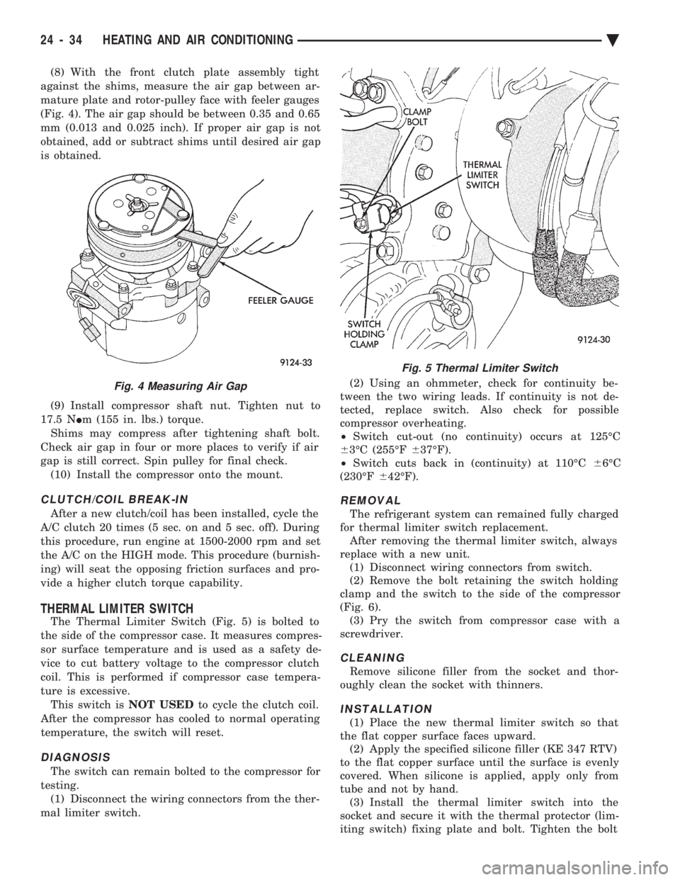
(8) With the front clutch plate assembly tight
against the shims, measure the air gap between ar-
mature plate and rotor-pulley face with feeler gauges
(Fig. 4). The air gap should be between 0.35 and 0.65
mm (0.013 and 0.025 inch). If proper air gap is not
obtained, add or subtract shims until desired air gap
is obtained.
(9) Install compressor shaft nut. Tighten nut to
17.5 N Im (155 in. lbs.) torque.
Shims may compress after tightening shaft bolt.
Check air gap in four or more places to verify if air
gap is still correct. Spin pulley for final check. (10) Install the compressor onto the mount.
CLUTCH/COIL BREAK-IN
After a new clutch/coil has been installed, cycle the
A/C clutch 20 times (5 sec. on and 5 sec. off). During
this procedure, run engine at 1500-2000 rpm and set
the A/C on the HIGH mode. This procedure (burnish-
ing) will seat the opposing friction surfaces and pro-
vide a higher clutch torque capability.
THERMAL LIMITER SWITCH
The Thermal Limiter Switch (Fig. 5) is bolted to
the side of the compressor case. It measures compres-
sor surface temperature and is used as a safety de-
vice to cut battery voltage to the compressor clutch
coil. This is performed if compressor case tempera-
ture is excessive. This switch is NOT USEDto cycle the clutch coil.
After the compressor has cooled to normal operating
temperature, the switch will reset.
DIAGNOSIS
The switch can remain bolted to the compressor for
testing. (1) Disconnect the wiring connectors from the ther-
mal limiter switch. (2) Using an ohmmeter, check for continuity be-
tween the two wiring leads. If continuity is not de-
tected, replace switch. Also check for possible
compressor overheating.
² Switch cut-out (no continuity) occurs at 125ÉC
6 3ÉC (255ÉF 637ÉF).
² Switch cuts back in (continuity) at 110ÉC 66ÉC
(230ÉF 642ÉF).
REMOVAL
The refrigerant system can remained fully charged
for thermal limiter switch replacement. After removing the thermal limiter switch, always
replace with a new unit. (1) Disconnect wiring connectors from switch.
(2) Remove the bolt retaining the switch holding
clamp and the switch to the side of the compressor
(Fig. 6). (3) Pry the switch from compressor case with a
screwdriver.
CLEANING
Remove silicone filler from the socket and thor-
oughly clean the socket with thinners.
INSTALLATION
(1) Place the new thermal limiter switch so that
the flat copper surface faces upward. (2) Apply the specified silicone filler (KE 347 RTV)
to the flat copper surface until the surface is evenly
covered. When silicone is applied, apply only from
tube and not by hand. (3) Install the thermal limiter switch into the
socket and secure it with the thermal protector (lim-
iting switch) fixing plate and bolt. Tighten the bolt
Fig. 4 Measuring Air Gap
Fig. 5 Thermal Limiter Switch
24 - 34 HEATING AND AIR CONDITIONING Ä