1993 CHEVROLET PLYMOUTH ACCLAIM check engine
[x] Cancel search: check enginePage 2376 of 2438
NONÐCOMPUTER AIDED DIAGNOSTIC TESTS
Determine whether the operator complaint is due
to a system failure or improper operation of the ATC
system. The system will to go into a maximum heat
or cooling mode if the operator changes the tempera-
ture setting four or more degrees. Check the following:
² Coolant level
² Refrigerant charge
² Drive belt tension
² Radiator air flow
² Radiator fan operation
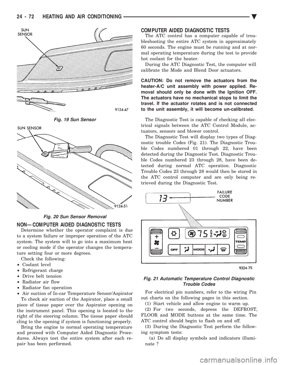
² Air suction of In-car Temperature Sensor/Aspirator
To check air suction of the Aspirator, place a small
piece of tissue paper over the Aspirator opening on
the instrument panel. This opening is located to the
right of the steering column. The tissue paper should
cling to the opening if system is functioning properly. Bring the engine to normal operating temperature
and proceed with Computer Aided Diagnostic Proce-
dures. Always test the entire system after each re-
pair has been performed.
COMPUTER AIDED DIAGNOSTIC TESTS
The ATC control has a computer capable of trou-
bleshooting the entire ATC system in approximately
60 seconds. The engine must be running and at nor-
mal operating temperature during the test to provide
hot coolant for the heater. During the ATC Diagnostic Test, the computer will
calibrate the Mode and Blend Door actuators.
CAUTION: Do not remove the actuators from the
heater-A/C unit assembly with power applied. Re-
moval should only be done with the Ignition OFF.
The actuators have no mechanical stops to limit the
travel. If the actuator rotates and is not connected
to the unit assembly, it will become un-calibrated.
The Diagnostic Test is capable of checking all elec-
trical signals between the ATC Control Module, ac-
tuators, sensors and blower control. The Diagnostic Test will display two types of Diag-
nostic trouble Codes (Fig. 21). The Diagnostic Trou-
ble Codes numbered 01 through 22, have been
detected during the Diagnostic Test. Diagnostic Trou-
ble Codes numbered 23 through 28, have been de-
tected during normal ATC operation. Diagnostic
Trouble Codes 23 through 28 would then be stored in
the ATC control computer and are only being re-
trieved during the Diagnostic Test.
For electrical pin numbers, refer to the wiring Pin
out charts on the following pages in this section. (1) Start vehicle and allow engine to warm up.
(2) For two seconds, depress the DEFROST,
FLOOR and MODE buttons at the same time. The
ATC control should begin to flash on and off. (3) During the Diagnostic Test perform the follow-
ing symptom tests: (a) Do all display symbols and indicators illumi-
nate ?
Fig. 19 Sun Sensor
Fig. 20 Sun Sensor Removal
Fig. 21 Automatic Temperature Control Diagnostic Trouble Codes
24 - 72 HEATING AND AIR CONDITIONING Ä
Page 2377 of 2438
(b) Does the blower motor operate at its highest
speed ? (c) Feel the outlet temperature. Does it get hot
and then cycle cold ? (d) Does the air flow switch from DEFROST out-
lets and then cycle to PANEL outlets?
If you can answer NO to any of these questions,
proceed to step 4, otherwise proceed to step 5. (4) If you answered NO to:
SYMPTOM A
The display symbols and indicators do not illumi-
nate. Diagnostic Trouble Codes are not displayed.
TEST
After self-diagnostic test is complete, select a mode
that will display the malfunction.
ACTION
If the ATC system operates properly, and the dis-
play does not, replace ATC control panel computer.
SYMPTOM B
The blower motor does not operate.
CAUTION: Stay clear of blower motor and power
module (PM) heat sink. Do not run system for more
than 10 minutes with PM removed from A/C unit.
TEST Check all power module and blower motor connec-
tions. Use a voltmeter to test for 12 volts (ignition)
at both ends of the fuse with ignition ON. If fuse is
good, test the green wire at the blower motor connec-
tor for 12 volts (ignition) to body ground. Turn ignition to the ON position.
With the blower motor still connected, check for 12
volts to body ground on the black/tan wire of the
blower motor two way connector. Check for 12 volts at the Power Module pin #4
(BK/TN). Check for continuity from the Power Module pin
#3 (BK) to chassis ground. Replace the Power Module.
ACTION If 12 volts is not detected, repair feed circuit. Refer
to the Front Wheel Drive Car-Wiring Diagrams Ser-
vice Manual. If 12 volts is not detected, repair wires of the
blower motor or replace the blower motor. If 12 volts is not present, repair wire from the
blower motor connector to the Power Module. If circuit is open, repair ground circuit of the Power
Module. Replace the Power Module (power transistor open).
SYMPTOM C
The outlet air temperature does not become hot
and then cycle to cold during self-test operation. Di-
agnostic Trouble Codes are not displayed.
TEST/ACTION
Make sure the blend-air door is properly attached
to the actuator. If cold air is not discharged from the outlets, check
the base A/C refrigerant system. Make sure heating operation works correctly, (wa-
ter level, thermostat, heater hoses, heater core, etc.).
SYMPTOM D
Air does not flow from DEFROST outlets and then
cycle to PANEL outlets during self-test operation.
TEST/ACTION Check linkages from the mode door actuator for
binding. Check for proper door travel in the unit.
(5) The computer will do one of two things:
² Will return to the control settings that were se-
lected before the Diagnostic Test was started. This
means the test is over. If Diagnostic Trouble Codes
did not occur, and answers to questions (a), (b), (c),
and (d) were YES, the entire system is operating cor-
rectly.
² The blower motor will stop and the computer will
flash a Diagnostic Trouble Code number from 01
through 28. Record the number and then depress the
PANEL button to advance to the next test. If the
ATC control flashes one or more codes 23 to 28, the
digits on the display will flash alternating Zeros. If
you do nothing, these codes will remain stored within
the ATC control computer. After all repairs have
been made erase fault codes. Refer to Erasing Diag-
nostic Trouble Codes 23 through 28 from ATC Con-
trol in this section. Repair all Diagnostic Trouble Codes in the order
that they have been indicated, and then retest the
system. If any blend door test fails, all remaining
blend door tests will be skipped. IF any mode door
tests fail, all remaining mode door tests will be
skipped. Diagnostic Test can be stopped at any time by de-
pressing any button other than PANEL.
DIAGNOSTIC TROUBLE CODE DEFINITIONS
Non-computer aided diagnostics should be per-
formed first. Hood of vehicle should be closed during
the diagnostic test to keep engine heat from effecting
the ambient temperature sensor. Also refer to the wiring Pin out charts.
² DIAGNOSTIC TROUBLE CODE 1
Involves the wiring or the ATC control head.
² DIAGNOSTIC TROUBLE CODES 2, 13, 14, 15,
20, and 23
Ä HEATING AND AIR CONDITIONING 24 - 73
Page 2382 of 2438
(1) Disconnect terminal #4 on the ATC control 21-
way connector and retest the system. Removing this
terminal may generate additional Diagnostic Trouble
Codes. Disregard these at this time. (2) If Diagnostic Trouble Code 4 reappears, replace
control. (3) If code 4 does not reappear, the problem is a
shorted actuator motor or a short to ground in circuit
#34 (pin #4). (4) Remove 21-way connector and check for conti-
nuity from pin #4 to chassis ground. There should
not be any continuity. If continuity is there, repair
wiring and retest. (5) Check resistance across pins #4 and #5, #4
and #6, and #4 and #15 of the 21-way connector for
a shorted actuator motor. Resistance should be be-
tween 20 and 50 ohms. If not correct, replace actua-
tor involved.
DIAGNOSTIC TROUBLE CODE 5ÐFRESH/ RECIRC ACTUATOR DRIVE SIGNAL NOT HIGH
If both Diagnostic Trouble Codes 4 and 5 oc-
cur simultaneously, do both procedures. There
is typically only 1 failure. (1) Disconnect terminal #15 on the ATC control
21-way connector and retest the system. Removing
this terminal may generate additional Diagnostic
Trouble Codes. Disregard these at this time. (2) If Diagnostic Trouble Code 5 reappears, replace
control. (3) If code 5 does not reappear, the problem is a
shorted fresh/recirc door actuator motor. It could also
be a short to ground in circuit #32 (pin #15). (4) Remove 21-way connector and check for conti-
nuity from pin #15 to chassis ground. There should
not be any continuity. If continuity is there, repair
wiring and retest. (5) Check resistance across pins #15 and #4 of the
21-way connector for a shorted actuator motor. Resis-
tance should be between 20 and 50 ohms. If not cor-
rect, replace actuator.
DIAGNOSTIC TROUBLE CODE 6ÐCOMPRESSOR DRIVE SIGNAL NOT HIGH
(1) Disconnect the low pressure cut out switch and
retest diagnostics. (2) If code 6 does not reappear, then the problem is
in the A/C signal circuit C02. Check for wiring prob-
lem between the low pressure cut out switch and the
engine controller, or a bad engine controller. (3) If code 6 does reappear, remove the 21-way con-
nector from the control and check for a short between
pin #13 and chassis ground. This test will check the
wire from the control to the low pressure cut out
switch for a short to ground.
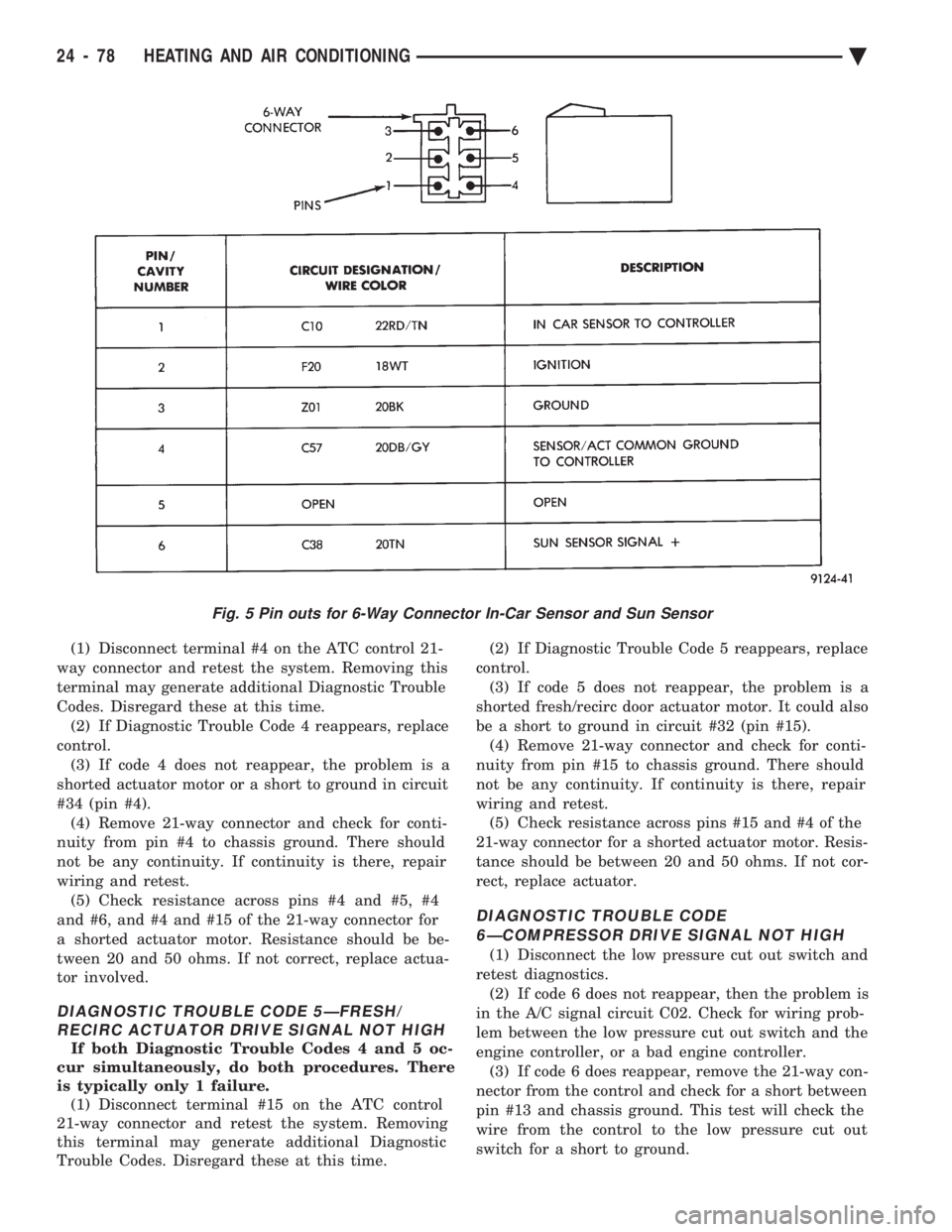
Fig. 5 Pin outs for 6-Way Connector In-Car Sensor and Sun Sensor
24 - 78 HEATING AND AIR CONDITIONING Ä
Page 2405 of 2438
EXHAUST EMISSION CONTROLS INDEX
page page
Air Aspiration System ..................... 24
EGR Gas Flow Test ...................... 21
EGR System On-Board Diagnostics ........... 21
EGR Tube ServiceÐ2.2L and 2.5L TBI Engines . 22
EGR Tube ServiceÐ3.0L Engines ............ 22
EGR Tube ServiceÐ3.3L and 3.8L Engines .... 22
EGR Valve ServiceÐ2.2L and 2.5L TBI Engines . 22 EGR Valve ServiceÐ3.0L Engines
........... 22
EGR Valve ServiceÐ3.3L and 3.8L Engines .... 22
Exhaust Gas Recirculation (EGR) System ...... 20
Exhaust Gas Recirculation (EGR) System Test . . 21
Heated Inlet Air System ................... 17
Heated Oxygen Sensor (O
2Sensor) .......... 18
HEATED INLET AIR SYSTEM
2.5L MPI (Flexible Fuel AA-body), Turbo III, 3.0L,
3.3L and 3.8L engines do not use a heated inlet air
system. 2.2L and 2.5L TBI air cleaners have a heated air
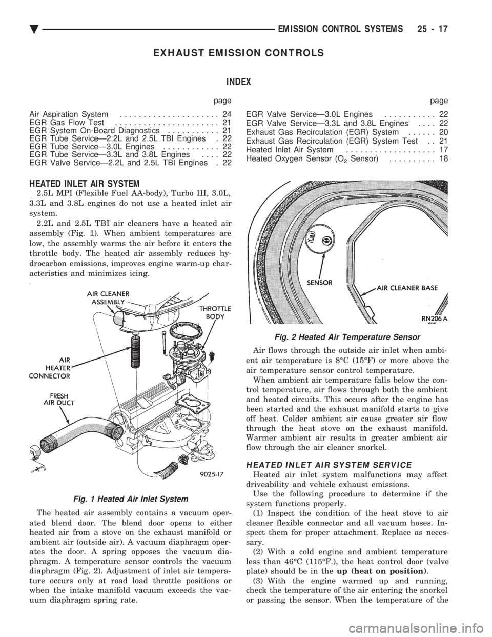
assembly (Fig. 1). When ambient temperatures are
low, the assembly warms the air before it enters the
throttle body. The heated air assembly reduces hy-
drocarbon emissions, improves engine warm-up char-
acteristics and minimizes icing.
The heated air assembly contains a vacuum oper-
ated blend door. The blend door opens to either
heated air from a stove on the exhaust manifold or
ambient air (outside air). A vacuum diaphragm oper-
ates the door. A spring opposes the vacuum dia-
phragm. A temperature sensor controls the vacuum
diaphragm (Fig. 2). Adjustment of inlet air tempera-
ture occurs only at road load throttle positions or
when the intake manifold vacuum exceeds the vac-
uum diaphragm spring rate. Air flows through the outside air inlet when ambi-
ent air temperature is 8ÉC (15ÉF) or more above the
air temperature sensor control temperature. When ambient air temperature falls below the con-
trol temperature, air flows through both the ambient
and heated circuits. This occurs after the engine has
been started and the exhaust manifold starts to give
off heat. Colder ambient air cause greater air flow
through the heat stove on the exhaust manifold.
Warmer ambient air results in greater ambient air
flow through the air cleaner snorkel.
HEATED INLET AIR SYSTEM SERVICE
Heated air inlet system malfunctions may affect
driveability and vehicle exhaust emissions. Use the following procedure to determine if the
system functions properly. (1) Inspect the condition of the heat stove to air
cleaner flexible connector and all vacuum hoses. In-
spect them for proper attachment. Replace as neces-
sary. (2) With a cold engine and ambient temperature
less than 46ÉC (115ÉF.), the heat control door (valve
plate) should be in the up (heat on position).
(3) With the engine warmed up and running,
check the temperature of the air entering the snorkel
or passing the sensor. When the temperature of the
Fig. 1 Heated Air Inlet System
Fig. 2 Heated Air Temperature Sensor
Ä EMISSION CONTROL SYSTEMS 25 - 17
Page 2406 of 2438
air entering the outer end of snorkel is 60ÉC (140ÉF.) or
higher, the door should be in the down (heat off)
position. (4) Remove the air cleaner from the engine and
allow it to cool down to 46ÉC (115ÉF). With 20 inches of
vacuum applied to the sensor, the door should be in the
up (heat on position). If the door does not rise to the
heat on position, check the vacuum diaphragm for
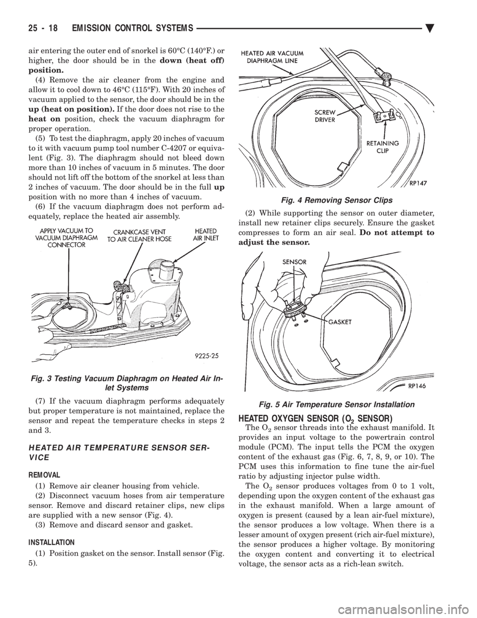
proper operation. (5) To test the diaphragm, apply 20 inches of vacuum
to it with vacuum pump tool number C-4207 or equiva-
lent (Fig. 3). The diaphragm should not bleed down
more than 10 inches of vacuum in 5 minutes. The door
should not lift off the bottom of the snorkel at less than
2 inches of vacuum. The door should be in the full up
position with no more than 4 inches of vacuum. (6) If the vacuum diaphragm does not perform ad-
equately, replace the heated air assembly.
(7) If the vacuum diaphragm performs adequately
but proper temperature is not maintained, replace the
sensor and repeat the temperature checks in steps 2
and 3.
HEATED AIR TEMPERATURE SENSOR SER- VICE
REMOVAL
(1) Remove air cleaner housing from vehicle.
(2) Disconnect vacuum hoses from air temperature
sensor. Remove and discard retainer clips, new clips
are supplied with a new sensor (Fig. 4). (3) Remove and discard sensor and gasket.
INSTALLATION (1) Position gasket on the sensor. Install sensor (Fig.
5). (2) While supporting the sensor on outer diameter,
install new retainer clips securely. Ensure the gasket
compresses to form an air seal. Do not attempt to
adjust the sensor.
HEATED OXYGEN SENSOR (O2SENSOR)
The O2sensor threads into the exhaust manifold. It
provides an input voltage to the powertrain control
module (PCM). The input tells the PCM the oxygen
content of the exhaust gas (Fig. 6, 7, 8, 9, or 10). The
PCM uses this information to fine tune the air-fuel
ratio by adjusting injector pulse width. The O
2sensor produces voltages from 0 to 1 volt,
depending upon the oxygen content of the exhaust gas
in the exhaust manifold. When a large amount of
oxygen is present (caused by a lean air-fuel mixture),
the sensor produces a low voltage. When there is a
lesser amount of oxygen present (rich air-fuel mixture),
the sensor produces a higher voltage. By monitoring
the oxygen content and converting it to electrical
voltage, the sensor acts as a rich-lean switch.
Fig. 3 Testing Vacuum Diaphragm on Heated Air In- let Systems
Fig. 4 Removing Sensor Clips
Fig. 5 Air Temperature Sensor Installation
25 - 18 EMISSION CONTROL SYSTEMS Ä
Page 2409 of 2438
These systems do not allow EGR at idle. The 2.2L/
2.5L EGR systems operate at all temperatures. The
3.0L, 3.3L and 3.8L EGR systems do not operate
when coolant temperature is below 4.5ÉC (40É)F at
start-up. These systems activate when coolant tem-
perature reaches 77ÉC (170ÉF).
EGR SYSTEM ON-BOARD DIAGNOSTICS
The powertrain control module (PCM) performs an
on-board diagnostic check of the EGR system on all
California vehicles with EGR systems. The diagnos-
tic system uses the Electric EGR Transducer (EET)
for the system tests. The diagnostic check activates only during selected
engine/driving conditions. When the conditions are
met, the PCM energizes the transducer solenoid to
disable the EGR. The PCM checks for a change in the oxygen sensor signal. If the air-fuel mixture goes
lean, the PCM will attempt to enrichen the mixture.
The PCM registers a fault if the EGR system has
failed or degraded. After registering a fault, the PCM
turns on the malfunction indicator lamp (instrument
panel Check Engine light). The malfunction indicator
lamp indicates the need for immediate service.
If a problem is indicated by the malfunction indicator
lamp and a diagnostic trouble code for the EGR system,
check for proper operation of the EGR system. Use the
System Test, EGR Gas Flow Test and EGR Diagnosis
Chart. If the EGR system tests properly, check the sys-
tem using the DRBII scan tool. Refer to On-Board Di-
agnosis in the General Diagnosis sections of Group 14.
Also, refer to the DRBII scan tool and the appropriate
Powertrain Diagnostics Procedure manual.
EXHAUST GAS RECIRCULATION (EGR) SYSTEM
TEST
WARNING: APPLY PARKING BRAKE AND/OR
BLOCK WHEELS BEFORE PERFORMING EGR SYS-
TEM TEST.
A failed or malfunctioning EGR system can cause
engine spark knock, sags or hesitation, rough idle,
and/or engine stalling. To ensure proper operation of
the EGR system, all passages and moving parts must
be free of deposits that could cause plugging or stick-
ing. Ensure system hoses do not leak. Replace leak-
ing components. Inspect hose connections between the throttle body,
intake manifold, EGR solenoid and transducer, and
EGR valve. Replace hardened, cracked, or melted
hoses. Repair or replace faulty connectors.
Check the EGR control system and EGR valve with
the engine fully warmed up and running (engine cool-
ant temperature over 150ÉF). With the transmission in
neutral and the throttle closed, allow the engine to idle
for 70 seconds. Abruptly accelerate the engine to ap-
proximately 2000 rpm, but not over 3000 rpm. The EGR
valve stem should move when accelerating the engine
(the relative position of the groove on the EGR valve
stem should change). Repeat the test several times to
confirm movement. If the EGR valve stem moves, the
control system is operating normally. If the control sys-
tem is not operating normally, refer to the EGR Diag-
nosis Chart to determine the cause.
EGR GAS FLOW TEST
The following procedure should be used to determine
if exhaust gas is flowing through the EGR system.
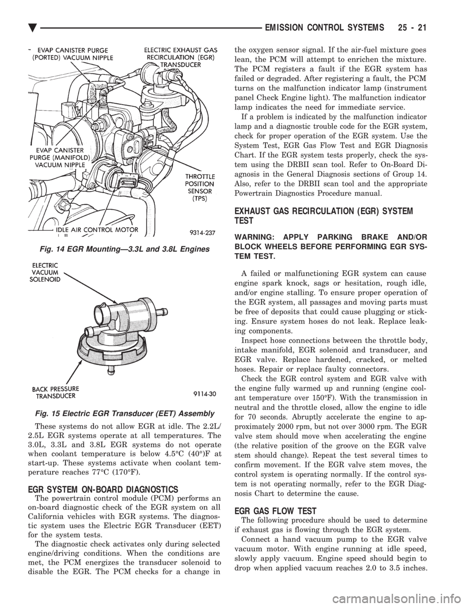
Connect a hand vacuum pump to the EGR valve
vacuum motor. With engine running at idle speed,
slowly apply vacuum. Engine speed should begin to
drop when applied vacuum reaches 2.0 to 3.5 inches.
Fig. 14 EGR MountingÐ3.3L and 3.8L Engines
Fig. 15 Electric EGR Transducer (EET) Assembly
Ä EMISSION CONTROL SYSTEMS 25 - 21
Page 2410 of 2438
Engine speed may drop quickly or engine may even
stall. This indicates that EGR gas is flowing through
the system.If both the EGR Gas Flow Check, System Check
and Diagnosis Chart are completed satisfactorily,
then the EGR system functions normally. If engine speed does not drop off when performing
the test, remove both the EGR valve and EGR tube
and check for plugged passages. Also, check the in-
take manifold inlet passage. Clean or replace these
components for restoration of proper flow.
EGR VALVE SERVICEÐ2.2L AND 2.5L TBI
ENGINES
REMOVAL
(1) Disconnect electrical connector and vacuum
line from the electric EGR transducer (Fig. 12). (2) Remove EGR valve bolts from intake manifold.
(3) Remove EGR valve from intake manifold.
(4) Clean gasket surface and discard old gasket.
Check for any signs of leakage or cracked surfaces.
INSTALLATION
(1) Assemble EGR valve with new gasket onto the
intake manifold. (2) Install EGR valve mounting bolts. Tighten to
22 N Im (200 in. lbs.) torque.
(3) Reconnect vacuum line and electrical connector
to Electric EGR Transducer.
EGR TUBE SERVICEÐ2.2L AND 2.5L TBI ENGINES
REMOVAL
(1) Remove EGR tube attaching bolts from intake
and exhaust manifolds. (2) Remove EGR tube.
(3) Clean intake and exhaust manifold gasket sur-
faces and EGR tube flange gasket surfaces. Discard
old gaskets. (4) Check for signs of leakage or cracked surfaces
on either manifolds or tube. Replace as necessary.
INSTALLATION
(1) Loosely position EGR tube and new gaskets in
place on intake and exhaust manifolds. Install
mounting bolts. (2) Tighten attaching bolts to 22 N Im (200 in. lbs.)
torque.
EGR VALVE SERVICEÐ3.0L ENGINES
REMOVAL
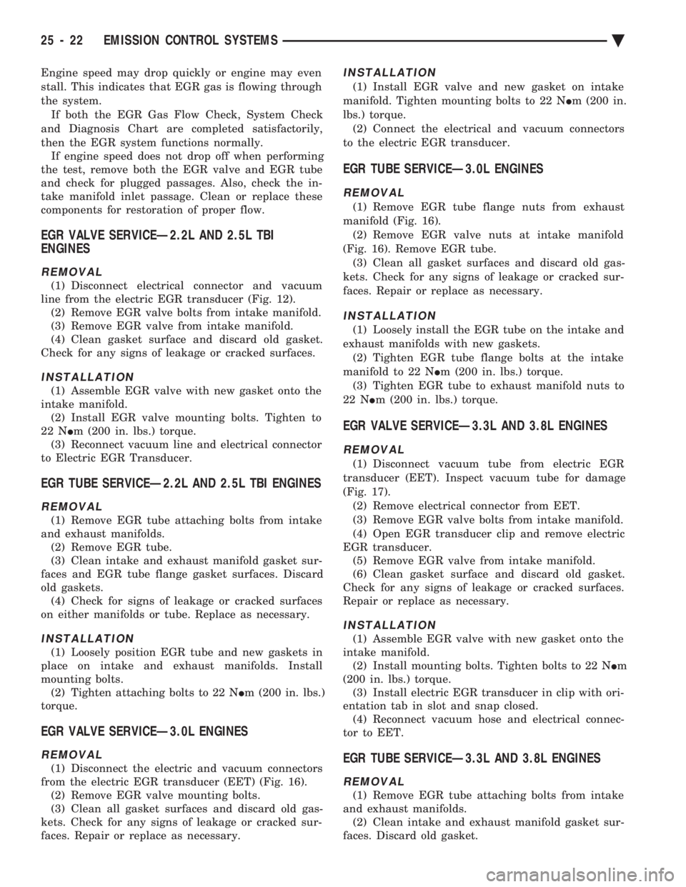
(1) Disconnect the electric and vacuum connectors
from the electric EGR transducer (EET) (Fig. 16). (2) Remove EGR valve mounting bolts.
(3) Clean all gasket surfaces and discard old gas-
kets. Check for any signs of leakage or cracked sur-
faces. Repair or replace as necessary.
INSTALLATION
(1) Install EGR valve and new gasket on intake
manifold. Tighten mounting bolts to 22 N Im (200 in.
lbs.) torque. (2) Connect the electrical and vacuum connectors
to the electric EGR transducer.
EGR TUBE SERVICEÐ3.0L ENGINES
REMOVAL
(1) Remove EGR tube flange nuts from exhaust
manifold (Fig. 16). (2) Remove EGR valve nuts at intake manifold
(Fig. 16). Remove EGR tube. (3) Clean all gasket surfaces and discard old gas-
kets. Check for any signs of leakage or cracked sur-
faces. Repair or replace as necessary.
INSTALLATION
(1) Loosely install the EGR tube on the intake and
exhaust manifolds with new gaskets. (2) Tighten EGR tube flange bolts at the intake
manifold to 22 N Im (200 in. lbs.) torque.
(3) Tighten EGR tube to exhaust manifold nuts to
22 N Im (200 in. lbs.) torque.
EGR VALVE SERVICEÐ3.3L AND 3.8L ENGINES
REMOVAL
(1) Disconnect vacuum tube from electric EGR
transducer (EET). Inspect vacuum tube for damage
(Fig. 17). (2) Remove electrical connector from EET.
(3) Remove EGR valve bolts from intake manifold.
(4) Open EGR transducer clip and remove electric
EGR transducer. (5) Remove EGR valve from intake manifold.
(6) Clean gasket surface and discard old gasket.
Check for any signs of leakage or cracked surfaces.
Repair or replace as necessary.
INSTALLATION
(1) Assemble EGR valve with new gasket onto the
intake manifold. (2) Install mounting bolts. Tighten bolts to 22 N Im
(200 in. lbs.) torque. (3) Install electric EGR transducer in clip with ori-
entation tab in slot and snap closed. (4) Reconnect vacuum hose and electrical connec-
tor to EET.
EGR TUBE SERVICEÐ3.3L AND 3.8L ENGINES
REMOVAL
(1) Remove EGR tube attaching bolts from intake
and exhaust manifolds. (2) Clean intake and exhaust manifold gasket sur-
faces. Discard old gasket.
25 - 22 EMISSION CONTROL SYSTEMS Ä
Page 2412 of 2438
(3) Check for signs of leakage or cracked surfaces
on either manifolds or tube. Repair or replace as nec-
essary.
INSTALLATION
(1) Loosely assemble EGR tube and new gaskets
into place on intake and exhaust manifolds. (2) Tighten mounting bolts to 22 N Im (200 in. lbs.)
torque.
AIR ASPIRATION SYSTEM
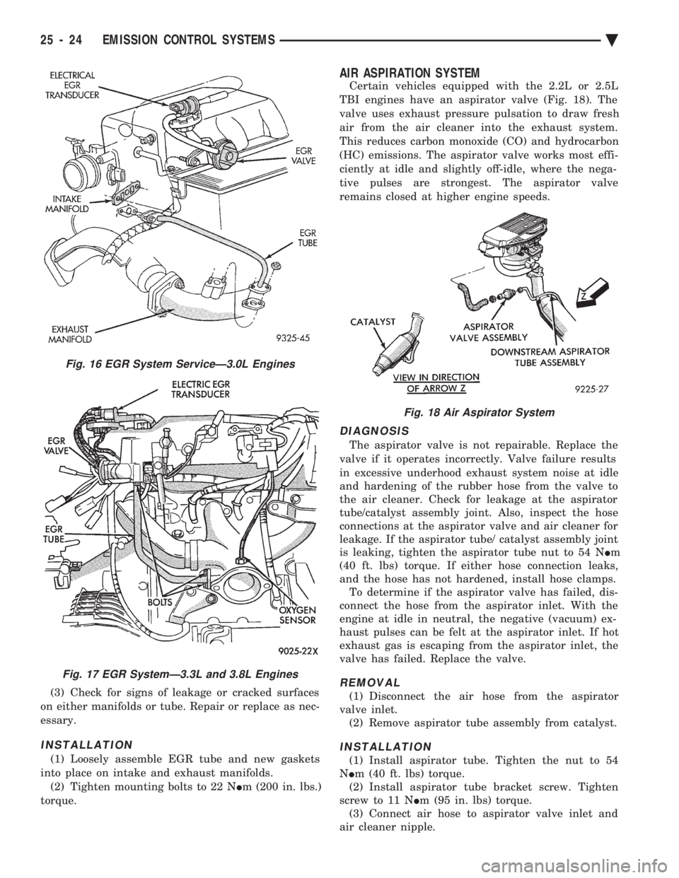
Certain vehicles equipped with the 2.2L or 2.5L
TBI engines have an aspirator valve (Fig. 18). The
valve uses exhaust pressure pulsation to draw fresh
air from the air cleaner into the exhaust system.
This reduces carbon monoxide (CO) and hydrocarbon
(HC) emissions. The aspirator valve works most effi-
ciently at idle and slightly off-idle, where the nega-
tive pulses are strongest. The aspirator valve
remains closed at higher engine speeds.
DIAGNOSIS
The aspirator valve is not repairable. Replace the
valve if it operates incorrectly. Valve failure results
in excessive underhood exhaust system noise at idle
and hardening of the rubber hose from the valve to
the air cleaner. Check for leakage at the aspirator
tube/catalyst assembly joint. Also, inspect the hose
connections at the aspirator valve and air cleaner for
leakage. If the aspirator tube/ catalyst assembly joint
is leaking, tighten the aspirator tube nut to 54 N Im
(40 ft. lbs) torque. If either hose connection leaks,
and the hose has not hardened, install hose clamps. To determine if the aspirator valve has failed, dis-
connect the hose from the aspirator inlet. With the
engine at idle in neutral, the negative (vacuum) ex-
haust pulses can be felt at the aspirator inlet. If hot
exhaust gas is escaping from the aspirator inlet, the
valve has failed. Replace the valve.
REMOVAL
(1) Disconnect the air hose from the aspirator
valve inlet. (2) Remove aspirator tube assembly from catalyst.
INSTALLATION
(1) Install aspirator tube. Tighten the nut to 54
N Im (40 ft. lbs) torque.
(2) Install aspirator tube bracket screw. Tighten
screw to 11 N Im (95 in. lbs) torque.
(3) Connect air hose to aspirator valve inlet and
air cleaner nipple.
Fig. 16 EGR System ServiceÐ3.0L Engines
Fig. 17 EGR SystemÐ3.3L and 3.8L Engines
Fig. 18 Air Aspirator System
25 - 24 EMISSION CONTROL SYSTEMS Ä