1993 CHEVROLET PLYMOUTH ACCLAIM tire type
[x] Cancel search: tire typePage 731 of 2438
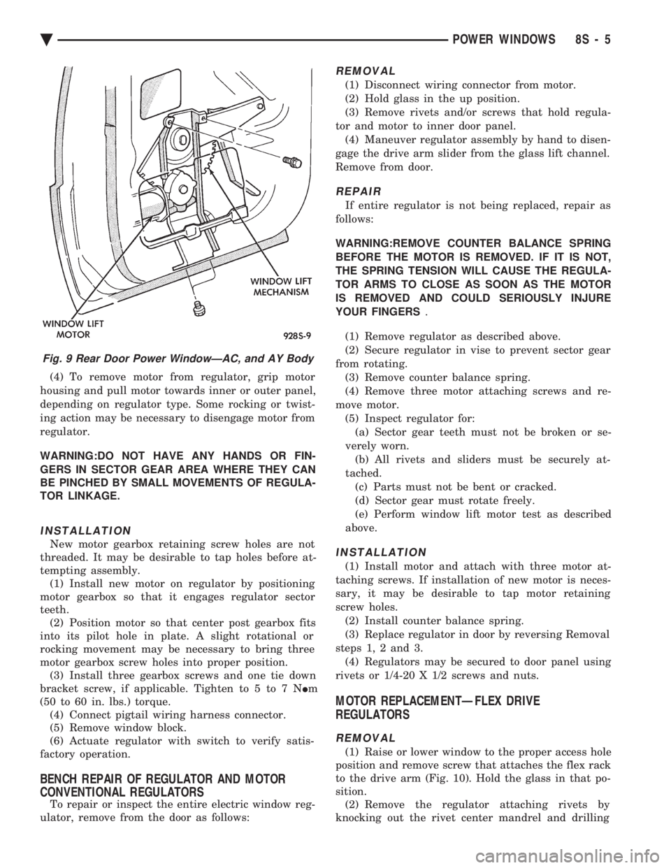
(4) To remove motor from regulator, grip motor
housing and pull motor towards inner or outer panel,
depending on regulator type. Some rocking or twist-
ing action may be necessary to disengage motor from
regulator.
WARNING:DO NOT HAVE ANY HANDS OR FIN-
GERS IN SECTOR GEAR AREA WHERE THEY CAN
BE PINCHED BY SMALL MOVEMENTS OF REGULA-
TOR LINKAGE.
INSTALLATION
New motor gearbox retaining screw holes are not
threaded. It may be desirable to tap holes before at-
tempting assembly. (1) Install new motor on regulator by positioning
motor gearbox so that it engages regulator sector
teeth. (2) Position motor so that center post gearbox fits
into its pilot hole in plate. A slight rotational or
rocking movement may be necessary to bring three
motor gearbox screw holes into proper position. (3) Install three gearbox screws and one tie down
bracket screw, if applicable. Tighten to 5 to 7 N Im
(50 to 60 in. lbs.) torque. (4) Connect pigtail wiring harness connector.
(5) Remove window block.
(6) Actuate regulator with switch to verify satis-
factory operation.
BENCH REPAIR OF REGULATOR AND MOTOR
CONVENTIONAL REGULATORS
To repair or inspect the entire electric window reg-
ulator, remove from the door as follows:
REMOVAL
(1) Disconnect wiring connector from motor.
(2) Hold glass in the up position.
(3) Remove rivets and/or screws that hold regula-
tor and motor to inner door panel. (4) Maneuver regulator assembly by hand to disen-
gage the drive arm slider from the glass lift channel.
Remove from door.
REPAIR
If entire regulator is not being replaced, repair as
follows:
WARNING:REMOVE COUNTER BALANCE SPRING
BEFORE THE MOTOR IS REMOVED. IF IT IS NOT,
THE SPRING TENSION WILL CAUSE THE REGULA-
TOR ARMS TO CLOSE AS SOON AS THE MOTOR
IS REMOVED AND COULD SERIOUSLY INJURE
YOUR FINGERS .
(1) Remove regulator as described above.
(2) Secure regulator in vise to prevent sector gear
from rotating. (3) Remove counter balance spring.
(4) Remove three motor attaching screws and re-
move motor. (5) Inspect regulator for:(a) Sector gear teeth must not be broken or se-
verely worn. (b) All rivets and sliders must be securely at-
tached. (c) Parts must not be bent or cracked.
(d) Sector gear must rotate freely.
(e) Perform window lift motor test as described
above.
INSTALLATION
(1) Install motor and attach with three motor at-
taching screws. If installation of new motor is neces-
sary, it may be desirable to tap motor retaining
screw holes. (2) Install counter balance spring.
(3) Replace regulator in door by reversing Removal
steps 1, 2 and 3. (4) Regulators may be secured to door panel using
rivets or 1/4-20 X 1/2 screws and nuts.
MOTOR REPLACEMENTÐFLEX DRIVE
REGULATORS
REMOVAL
(1) Raise or lower window to the proper access hole
position and remove screw that attaches the flex rack
to the drive arm (Fig. 10). Hold the glass in that po-
sition. (2) Remove the regulator attaching rivets by
knocking out the rivet center mandrel and drilling
Fig. 9 Rear Door Power WindowÐAC, and AY Body
Ä POWER WINDOWS 8S - 5
Page 755 of 2438
When a fusible link blows it is important to find
out what the problem is. They are placed in the sys-
tem for protection against shorts. Which can be
caused by a component failure or wiring failures. Do
not just replace the fusible link to correct the
problem. When diagnosing a faulty fusible link it is impor-
tant to check the wire carefully. In some instances
the link may be blown and it will not show through
the insulation, the wire should be checked over its
entire length for internal breaks. (1) Disconnect battery negative cable.
(2) Cut out the blown portion of the fusible link.
(3) Strip 1 inch of insulation from each end of the
existing fusible link. (4) Place a piece of heat shrink tubing over one
side of the fusible link. Make sure the tubing will be
long enough to cover and seal the entire repair area. (5) Cut a replacement piece of fusible link approx-
imately two inches longer than the piece removed. (6) Remove one inch of insulation from each end of
the replacement fusible link. (7) Spread the strands of wire apart on each of the
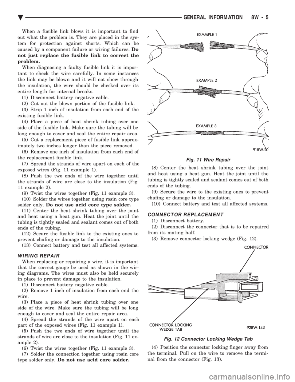
exposed wires (Fig. 11 example 1). (8) Push the two ends of the wire together until
the strands of wire are close to the insulation (Fig.
11 example 2). (9) Twist the wires together (Fig. 11 example 3).
(10) Solder the wires together using rosin core type
solder only. Do not use acid core type solder.
(11) Center the heat shrink tubing over the joint
and heat using a heat gun. Heat the joint until the
tubing is tightly sealed and sealant comes out of both
ends of the tubing. (12) Secure the fusible link to the existing ones to
prevent chafing or damage to the insulation. (13) Connect battery and test all affected systems.
WIRING REPAIR
When replacing or repairing a wire, it is important
that the correct gauge be used as shown in the wir-
ing diagrams. The wires must also be held securely
in place to prevent damage to the insulation. (1) Disconnect battery negative cable.
(2) Remove 1 inch of insulation from each end the
wire. (3) Place a piece of heat shrink tubing over one
side of the wire. Make sure the tubing will be long
enough to cover and seal the entire repair area. (4) Spread the strands of the wire apart on each
part of the exposed wires (Fig. 11 example 1). (5) Push the two ends of wire together until the
strands of wire are close to the insulation (Fig. 11 ex-
ample 2). (6) Twist the wires together (Fig. 11 example 3).
(7) Solder the connection together using rosin core
type solder only. Do not use acid core solder. (8) Center the heat shrink tubing over the joint
and heat using a heat gun. Heat the joint until the
tubing is tightly sealed and sealant comes out of both
ends of the tubing. (9) Secure the wire to the existing ones to prevent
chafing or damage to the insulation. (10) Connect battery and test all affected systems.
CONNECTOR REPLACEMENT
(1) Disconnect battery.
(2) Disconnect the connector that is to be repaired
from its mating half. (3) Remove connector locking wedge (Fig. 12).
(4) Position the connector locking finger away from
the terminal. Pull on the wire to remove the termi-
nal from the connector (Fig. 13).
Fig. 11 Wire Repair
Fig. 12 Connector Locking Wedge Tab
Ä GENERAL INFORMATION 8W - 5
Page 756 of 2438

(5) Reset the terminal locking tang, if it has one.
(6) Insert the removed wire in the same cavity on
the repair connector. (7) Repeat steps four thru six for each wire in the
connector. Check that all wires are inserted into the
proper cavities. For connector pin out identification
refer to the wiring diagrams. (8) Insert the connector locking wedge into the re-
paired connector. (9) Connect connector to its mating half.
(10) Connect battery and test all affected systems.
CONNECTOR AND TERMINAL ASSEMBLY REPLACEMENT
(1) Disconnect Battery.
(2) Disconnect the connector being repaired form
its mating half. (3) Cut off the existing wire connector directly be-
hind the insulator. Remove six inches of tape from
the harness. (4) Stagger cut all wires on the harness side about
1/2 inch apart (Fig. 14). (5) Remove 1 inch of insulation from each wire on
the harness side. (6) Stagger cut the matching wires on the repair
connector assembly in the opposite order as was done
on the harness side of the repair. Allow extra length
for soldered connections. Check that the overall
length is the same as the original (Fig. 14). (7) Remove 1 inch of insulation from each wire.
(8) Place a piece of heat shrink tubing over one
side of the wire. Make sure the tubing will be long
enough to cover and seal the entire repair area. (9) Spread the strands of the wire apart on each
part of the exposed wires (Fig. 11 example 1). (10) Push the two ends of wire together until the
strands of wire are close to the insulation (Fig. 11 ex-
ample 2). (11) Twist the wires together (Fig. 11 example 3). (12) Solder the connection together using rosin
core type solder only. Do not use acid core solder.
(13) Center the heat shrink tubing over the joint
and heat using a heat gun. Heat the joint until the
tubing is tightly sealed and sealant comes out of both
ends of the tubing. (14) Repeat steps 8 thru 13 for each wire.
(15) Re-tape the wire harness starting 1-1/2 inches
behind the connector and 2 inches past the repair. (16) Reconnect the repaired connector.
(17) Connect battery and test all affected systems.
TERMINAL REPLACEMENT
(1) Disconnect battery.
(2) Disconnect the connector being repaired form
its mating half. (3) Remove connector locking wedge (Fig. 12).
(4) Position the connector locking finger away from
the terminal. Pull on the wire to remove the termi-
nal from the connector (Fig. 13). (5) Cut the wire 6 inches from the back of the con-
nector. (6) Remove 1 inch of insulation from the wire on
the harness side. (7) Select a wire from the terminal repair assem-
bly that best matches the color wire being repaired. (8) Cut the repair wire to the proper length and re-
move 1 inch of insulation. (9) Place a piece of heat shrink tubing over one
side of the wire. Make sure the tubing will be long
enough to cover and seal the entire repair area. (10) Spread the strands of the wire apart on each
part of the exposed wires (Fig. 11 example 1). (11) Push the two ends of wire together until the
strands of wire are close to the insulation (Fig. 11 ex-
ample 2). (12) Twist the wires together (Fig. 11 example 3).
(13) Solder the connection together using rosin
core type solder only. Do not use acid core solder.
Fig. 13 Connector Locking Finger and Locking
Wedge
Fig. 14 Stagger Cutting Wires
8W - 6 GENERAL INFORMATION Ä
Page 1709 of 2438
(13) Disconnect articulated exhaust pipe joint from
turbocharger housing. (14) Remove turbocharger coolant inlet line assem-
bly from engine (Fig. 11). (15) Lift turbocharger off manifold mounting studs
and lower assembly down and out of vehicle.
EXHAUST MANIFOLD
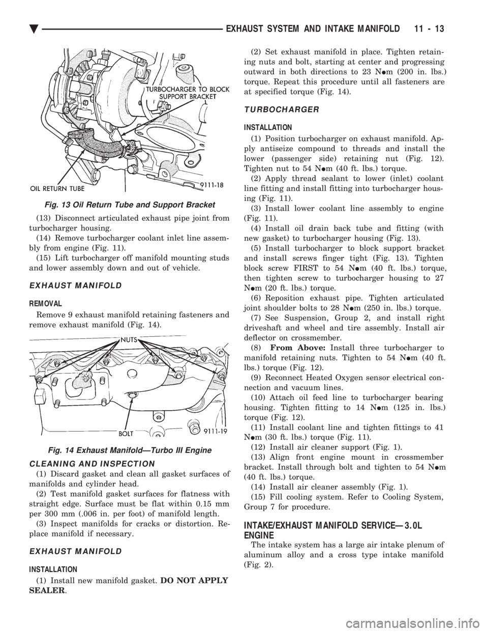
REMOVAL
Remove 9 exhaust manifold retaining fasteners and
remove exhaust manifold (Fig. 14).
CLEANING AND INSPECTION
(1) Discard gasket and clean all gasket surfaces of
manifolds and cylinder head. (2) Test manifold gasket surfaces for flatness with
straight edge. Surface must be flat within 0.15 mm
per 300 mm (.006 in. per foot) of manifold length. (3) Inspect manifolds for cracks or distortion. Re-
place manifold if necessary.
EXHAUST MANIFOLD
INSTALLATION
(1) Install new manifold gasket. DO NOT APPLY
SEALER . (2) Set exhaust manifold in place. Tighten retain-
ing nuts and bolt, starting at center and progressing
outward in both directions to 23 N Im (200 in. lbs.)
torque. Repeat this procedure until all fasteners are
at specified torque (Fig. 14).
TURBOCHARGER
INSTALLATION
(1) Position turbocharger on exhaust manifold. Ap-
ply antiseize compound to threads and install the
lower (passenger side) retaining nut (Fig. 12).
Tighten nut to 54 N Im (40 ft. lbs.) torque.
(2) Apply thread sealant to lower (inlet) coolant
line fitting and install fitting into turbocharger hous-
ing (Fig. 11). (3) Install lower coolant line assembly to engine
(Fig. 11). (4) Install oil drain back tube and fitting (with
new gasket) to turbocharger housing (Fig. 13). (5) Install turbocharger to block support bracket
and install screws finger tight (Fig. 13). Tighten
block screw FIRST to 54 N Im (40 ft. lbs.) torque,
then tighten screw to turbocharger housing to 27
N Im (20 ft. lbs.) torque.
(6) Reposition exhaust pipe. Tighten articulated
joint shoulder bolts to 28 N Im (250 in. lbs.) torque.
(7) See Suspension, Group 2, and install right
driveshaft and wheel and tire assembly. Install air
deflector on crossmember. (8) From Above: Install three turbocharger to
manifold retaining nuts. Tighten to 54 N Im (40 ft.
lbs.) torque (Fig. 12). (9) Reconnect Heated Oxygen sensor electrical con-
nection and vacuum lines. (10) Attach oil feed line to turbocharger bearing
housing. Tighten fitting to 14 N Im (125 in. lbs.)
torque (Fig. 12). (11) Install coolant line and tighten fittings to 41
N Im (30 ft. lbs.) torque (Fig. 11).
(12) Install air cleaner support (Fig. 1).
(13) Align front engine mount in crossmember
bracket. Install through bolt and tighten to 54 N Im
(40 ft. lbs.) torque. (14) Install air cleaner assembly (Fig. 1).
(15) Fill cooling system. Refer to Cooling System,
Group 7 for procedure.
INTAKE/EXHAUST MANIFOLD SERVICEÐ3.0L
ENGINE
The intake system has a large air intake plenum of
aluminum alloy and a cross type intake manifold
(Fig. 2).
Fig. 13 Oil Return Tube and Support Bracket
Fig. 14 Exhaust ManifoldÐTurbo III Engine
Ä EXHAUST SYSTEM AND INTAKE MANIFOLD 11 - 13
Page 1928 of 2438
CAUTION: The following test procedure involves test-
ing power steering pump maximum pressure output
and flow control valve operation. Do not leave valve
closed for more than 5 seconds as the pump could be
damaged.
(8) Close valve fully three times and record highest
pressure indicated each time. All three readings
must be above specifications and within 345 kPa
(50 psi) of each other. Power steering pump maximum relief pressure
is 8275 to 8975 kPa (1200 to 1300 psi.).
² Power steering pump pressures above specifications
but not within 345 kPa (50 psi) of each other, replace
pump.
² Pressures within 345 kPa (50 psi) of each other but
below specifications, replace pump.
CAUTION: Do not force the pump to operate against
the stops for more than 5 seconds at a time because,
pump damage will result.
(9) Open test valve. Turn steering wheel to the
extreme left and right positions until against the stops,
recording the highest indicated pressure at each posi-
tion. Compare pressure gauge readings to power steer-
ing pump specifications. If highest output pressures
are not the same against either stop, the steering gear
is leaking internally and must be replaced.
POWER STEERING PRESSURE SWITCH
New for 1993 M.Y., is the use of an idle quality power
steering pressure switch on some front wheel drive
passenger car applications. The purpose of this switch is to signal the power
train control module, that the power steering system is
putting additional load on the engine. This type of
condition exists when turning the front tires of the
vehicle, when the vehicle is stationary and the engine
is at idle speed. When this condition is sensed by the
power train control module, through a signal from the power steering pressure switch, engine idle
speed is increased. This increase in engine idle speed
compensates for the additional load, thus maintain-
ing the require engine idle speed and idle quality.
The power steering pressure switch is mounted to
the power steering pressure hose on the applications
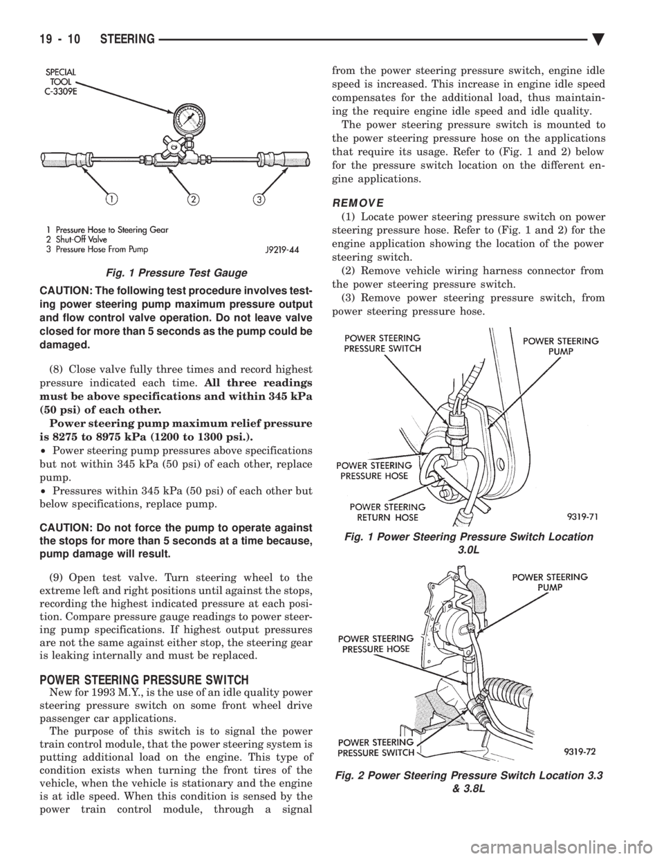
that require its usage. Refer to (Fig. 1 and 2) below
for the pressure switch location on the different en-
gine applications.
REMOVE
(1) Locate power steering pressure switch on power
steering pressure hose. Refer to (Fig. 1 and 2) for the
engine application showing the location of the power
steering switch. (2) Remove vehicle wiring harness connector from
the power steering pressure switch. (3) Remove power steering pressure switch, from
power steering pressure hose.
Fig. 1 Power Steering Pressure Switch Location 3.0L
Fig. 2 Power Steering Pressure Switch Location 3.3 & 3.8L
Fig. 1 Pressure Test Gauge
19 - 10 STEERING Ä
Page 1945 of 2438
bolts and nut on locating stud (Fig. 2). The right rear
crossmember stud is a pilot that correctly locates
the crossmember. Tighten down this bolt first,
then torque all 4 crossmember fasteners to 122
N Im (90 ft. lbs.).
CAUTION: Proper torque on the crossmember to
frame rail mounting bolts is very important.
(3) Torque the 4 bolts (Fig. 3) attaching the steering
gear assembly to front crossmember, to 68 N Im (50 ft.
lbs.). To ensure proper alignment of the steering
gear tighten left front bolt first. (4) Attach the engine damper strut from the engine
to the crossmember (if so equipped). (5) Attach the fluid tubes (Fig. 3) from the power
steering pump to the fittings on the steering gear.
Torque the fluid pressure line to steering gear tube nut
to 31 N Im (275 in. lbs.).
(6) Mount the outer tie rod ends to the steering
knuckles. Install the tie rod end to steering knuckle
attaching nuts. Torque the tie rod end to steering
knuckle nuts to 52 N Im (38 ft. lbs.). Install cotter pin
in tie rod end. (7) Install the front tire and wheel assemblies on
vehicle. Install the wheel lug nuts and torque to 129
N Im (95 ft. lbs.).
(8) Lower vehicle.
CAUTION: Do not use automatic transmission fluid. (9) Fill power steering pump fluid reservoir to the
(Full-Cold) proper level. (10) Start the engine and let run for a few seconds.
Then turn the engine off.
(11) Add fluid if necessary.
(12) Raise front wheels of vehicle off the ground.
(13) Start engine and turn steering wheel several
times from stop to stop to bleed air from fluid in
system. Stop engine, check fluid level, and inspect
system for leaks. Fill pump reservoir to correct
level with Mopar t, Power Steering Fluid, or
equivalent. See Checking Fluid Level.
(14) Lower front wheels of vehicle back on the
ground. (15) Adjust toe (Refer to Group 2 Suspension).
OUTER TIE ROD
REMOVAL
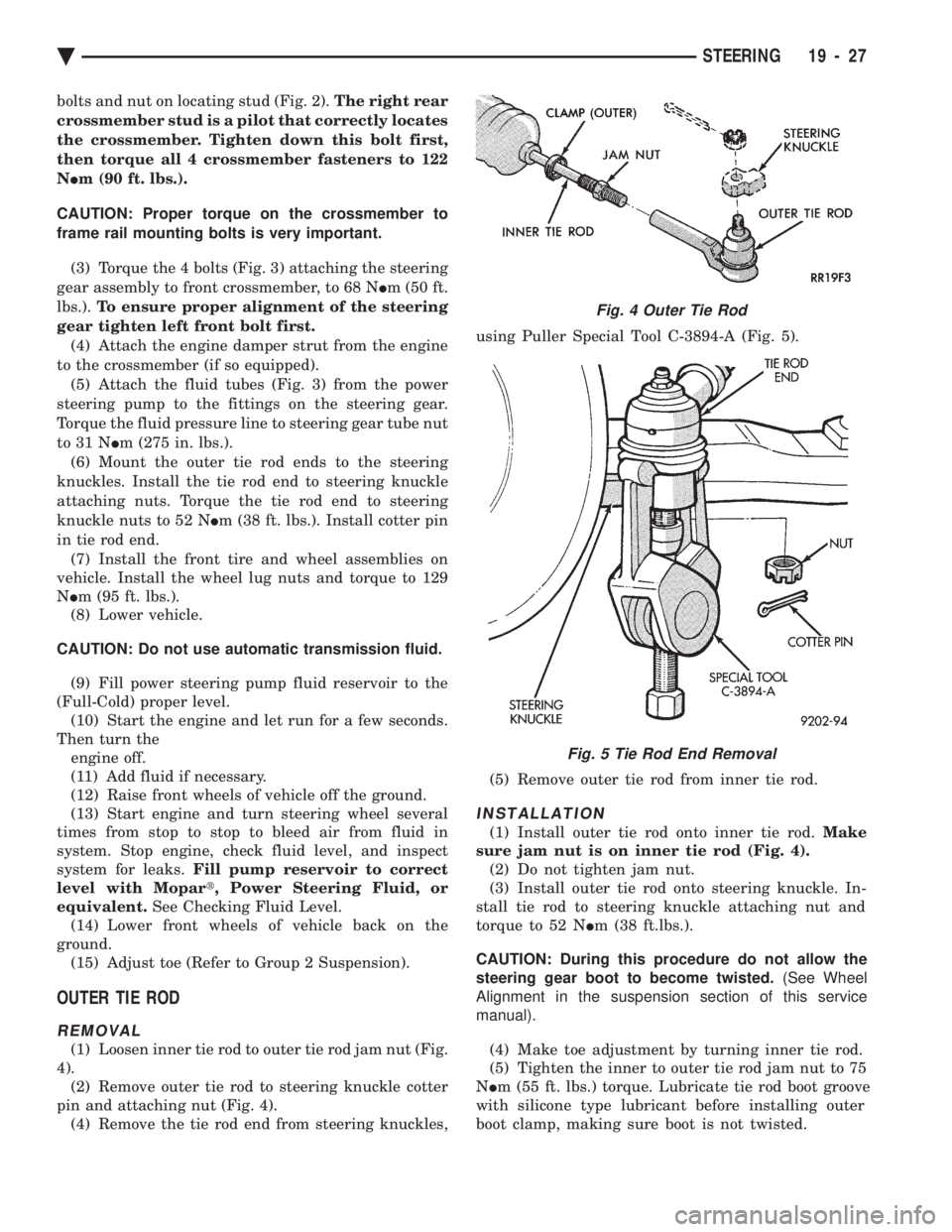
(1) Loosen inner tie rod to outer tie rod jam nut (Fig.
4). (2) Remove outer tie rod to steering knuckle cotter
pin and attaching nut (Fig. 4). (4) Remove the tie rod end from steering knuckles, using Puller Special Tool C-3894-A (Fig. 5).
(5) Remove outer tie rod from inner tie rod.
INSTALLATION
(1) Install outer tie rod onto inner tie rod. Make
sure jam nut is on inner tie rod (Fig. 4). (2) Do not tighten jam nut.
(3) Install outer tie rod onto steering knuckle. In-
stall tie rod to steering knuckle attaching nut and
torque to 52 N Im (38 ft.lbs.).
CAUTION: During this procedure do not allow the
steering gear boot to become twisted. (See Wheel
Alignment in the suspension section of this service
manual).
(4) Make toe adjustment by turning inner tie rod.
(5) Tighten the inner to outer tie rod jam nut to 75
N Im (55 ft. lbs.) torque. Lubricate tie rod boot groove
with silicone type lubricant before installing outer
boot clamp, making sure boot is not twisted.
Fig. 4 Outer Tie Rod
Fig. 5 Tie Rod End Removal
Ä STEERING 19 - 27
Page 2010 of 2438
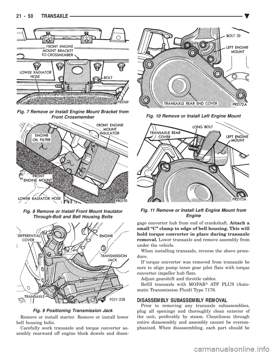
Remove or install starter. Remove or install lower
bell housing bolts. Carefully work transaxle and torque converter as-
sembly rearward off engine block dowels and disen- gage converter hub from end of crankshaft.
Attach a
small ``C'' clamp to edge of bell housing. This will
hold torque converter in place during transaxle
removal. Lower transaxle and remove assembly from
under the vehicle. When installing transaxle, reverse the above proce-
dure. If torque converter was removed from transaxle be
sure to align pump inner gear pilot flats with torque
converter impeller hub flats. Adjust gearshift and throttle cables.
Refill transaxle with MOPAR tATF PLUS (Auto-
matic Transmission Fluid) Type 7176.
DISASSEMBLY SUBASSEMBLY REMOVAL
Prior to removing any transaxle subassemblies,
plug all openings and thoroughly clean exterior of
the unit, preferably by steam. Cleanliness through
entire disassembly and assembly cannot be overem-
phasized. When disassembling, each part should be
Fig. 7 Remove or Install Engine Mount Bracket from Front Crossmember
Fig. 8 Remove or Install Front Mount InsulatorThrough-Bolt and Bell Housing Bolts
Fig. 9 Positioning Transmission Jack
Fig. 10 Remove or Install Left Engine Mount
Fig. 11 Remove or Install Left Engine Mount from Engine
21 - 50 TRANSAXLE Ä
Page 2149 of 2438
WHEELSÐTIRES
CONTENTS
page page
SPECIFICATIONS ........................ 8
TIRE SERVICE PROCEDURES .............. 1 WHEELS SERVICE PROCEDURES
........... 6
TIRE SERVICE PROCEDURES INDEX
page page
Cleaning of Tires .......................... 1
General Information ........................ 1
Pressure Gauges ......................... 2
Radial-Ply Tires ........................... 1
Repairing Leaks .......................... 3
Rotation ................................ 3 Spare TireÐCompact
...................... 1
Tire Inflation Pressures ..................... 2
Tire Noise or Vibration ..................... 3
Tire Wear Patterns ........................ 3
Tread Wear Indicators ...................... 3
GENERAL INFORMATION
Throughout this group, references may be made to a
particular vehicle by letter or number designation. A
chart showing the breakdown of these designations is
included in the Introduction Section. Tires are designed for the vehicle and provide the
best overall performance for normal operation. The
ride and handling characteristics match the vehicle's
requirements. With proper care they will give excellent
reliability traction, skid resistance and tread life. They
have load carrying capacity, when properly inflated, to
operate at loads up to the specified Maximum Vehicle
Capacity. Driving habits have more effect on tire life than any
other factor. Careful drivers will obtain, in most cases,
much greater mileage than severe or careless drivers. A
few of the driving habits which will shorten the life of
any tire are:
² Rapid acceleration and deceleration
² Severe application of brakes
² High-speed driving
² Taking turns at excessive speeds
² Striking curbs and other obstacles
Radial ply tires can be more susceptible to irregular
tread wear. It is very important to follow the tire
rotation interval shown in the section on Tire
Rotation to achieve a greater tread life potential.
RADIAL-PLY TIRES
Radial-ply tires improve handling, tread life, and
ride quality and decrease rolling resistance. Radial-ply tires must always be used in sets of four
and under no circumstances should they be used on
the front only. However, they may be mixed with temporary spare tires when necessary,
but reduced speeds are recommended. Radial-ply tires have the same load carrying capac-
ity as other types of tires of the same size. They also
use the same recommended inflation pressures.
SPARE TIREÐCOMPACT
The compact spare tire is designed for emergency
use only. The original tire should be repaired and re-
installed at the first opportunity. Refer to Owner's
Manual for complete details.
TIRE CHAINS
Tire snow chains may be used on certainmodels.
Refer to Owner's Manual for more information.
CLEANING OF TIRES
Remove protective coating on tires before delivery
of vehicle, otherwise it could cause deterioration of
tires. Remove protective coating by applying warm wa-
ter, letting it soak one minute, and then scrubbing
the coating away with a soft bristle brush. Steam cleaning may also be used for cleaning.
DO NOT use gasoline or wire brush for cleaning.
DO NOT use mineral oil or an oil-based solvent.
Ä WHEELSÐTIRES 22 - 1