1993 CHEVROLET PLYMOUTH ACCLAIM glove box
[x] Cancel search: glove boxPage 667 of 2438
EXTERIOR LAMP SYSTEMS INDEX
page page
Daytime Running LampÐCanada Only ........ 25
Headlamp Time Delay System .............. 26
Lamp Outage ModuleÐAA-Body ............. 25 Lamp Outage ModuleÐAll Except AA-Body
..... 25
Lamp Outage System ..................... 25
Removal (Fig. 4) ......................... 25
LAMP OUTAGE SYSTEM
Diagnostics and component relationships for AC,
AG, AJ or AY-Bodies can be found in the Body Di-
agnostic Procedures Manual, Electronic Vehicle In-
formation Center (EVIC) section. For circuit and component locations on AA-body,
refer to the Wiring Diagrams Manual.
LAMP OUTAGE MODULEÐALL EXCEPT AA-BODY
REMOVAL
(1) Remove battery negative cable.
(2) Remove the glove box assembly. Refer to Group
8E, Instrument Panel. (3) Disconnect the wire connector from the lamp
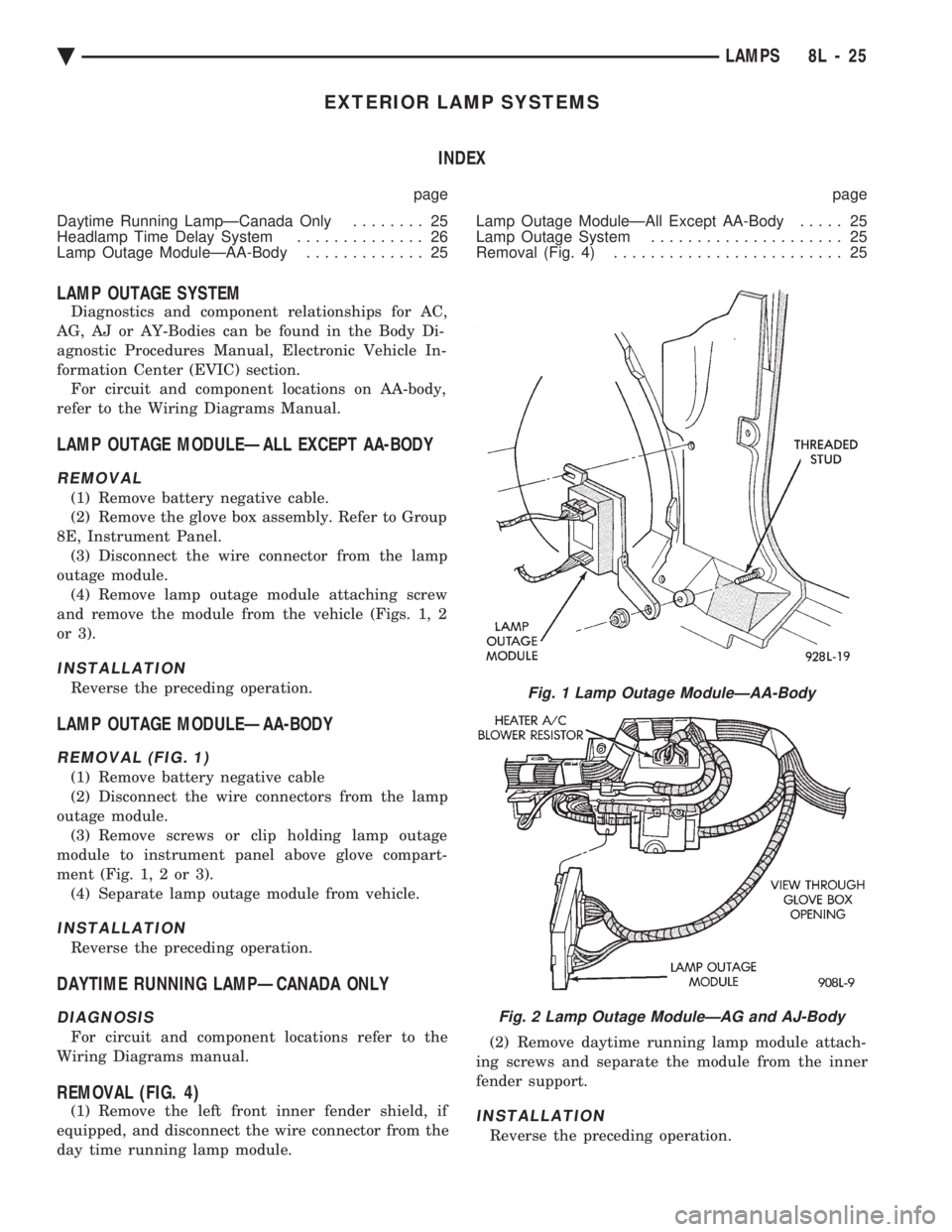
outage module. (4) Remove lamp outage module attaching screw
and remove the module from the vehicle (Figs. 1, 2
or 3).
INSTALLATION
Reverse the preceding operation.
LAMP OUTAGE MODULEÐAA-BODY
REMOVAL (FIG. 1)
(1) Remove battery negative cable
(2) Disconnect the wire connectors from the lamp
outage module. (3) Remove screws or clip holding lamp outage
module to instrument panel above glove compart-
ment (Fig. 1, 2 or 3). (4) Separate lamp outage module from vehicle.
INSTALLATION
Reverse the preceding operation.
DAYTIME RUNNING LAMPÐCANADA ONLY
DIAGNOSIS
For circuit and component locations refer to the
Wiring Diagrams manual.
REMOVAL (FIG. 4)
(1) Remove the left front inner fender shield, if
equipped, and disconnect the wire connector from the
day time running lamp module. (2) Remove daytime running lamp module attach-
ing screws and separate the module from the inner
fender support.INSTALLATION
Reverse the preceding operation.
Fig. 1 Lamp Outage ModuleÐAA-Body
Fig. 2 Lamp Outage ModuleÐAG and AJ-Body
Ä LAMPS 8L - 25
Page 675 of 2438
ILLUMINATED ENTRY SYSTEM INDEX
page page
Body Controller ComputerÐAC, AG, AJ and AY-Body ............................. 34
Diagnostic ProceduresÐAA-Body ............ 33 Diagnostic ProceduresÐAC, AG, AJ and AY-Body . 33
General Information ....................... 33
Illuminated Entry ModuleÐAA-Body ........... 34
GENERAL INFORMATION
AA-BODY
The Illuminated Entry System (on AA Body) actu-
ates the interior courtesy and/or dome lamps (except
for the illuminated ignition switch) by lifting either
front door exterior handle. Lamp illumination is terminated 35 seconds ( 68
seconds later when battery voltage is normal), or by
turning the ignition switch to the run position,
whichever occurs first. When testing the system, all
vehicle doors must be closed to prevent the door jam
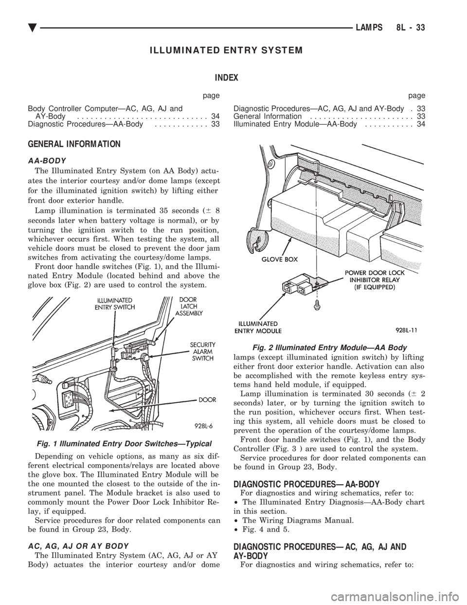
switches from activating the courtesy/dome lamps. Front door handle switches (Fig. 1), and the Illumi-
nated Entry Module (located behind and above the
glove box (Fig. 2) are used to control the system.
Depending on vehicle options, as many as six dif-
ferent electrical components/relays are located above
the glove box. The Illuminated Entry Module will be
the one mounted the closest to the outside of the in-
strument panel. The Module bracket is also used to
commonly mount the Power Door Lock Inhibitor Re-
lay, if equipped. Service procedures for door related components can
be found in Group 23, Body.
AC, AG, AJ OR AY BODY
The Illuminated Entry System (AC, AG, AJ or AY
Body) actuates the interior courtesy and/or dome lamps (except illuminated ignition switch) by lifting
either front door exterior handle. Activation can also
be accomplished with the remote keyless entry sys-
tems hand held module, if equipped. Lamp illumination is terminated 30 seconds ( 62
seconds) later, or by turning the ignition switch to
the run position, whichever occurs first. When test-
ing this system, all vehicle doors must be closed to
prevent the operation of the courtesy/dome lamps. Front door handle switches (Fig. 1), and the Body
Controller (Fig . 3 ) are used to control the system.
Service procedures for door related components can
be found in Group 23, Body.
DIAGNOSTIC PROCEDURESÐAA-BODY
For diagnostics and wiring schematics, refer to:
² The Illuminated Entry DiagnosisÐAA-Body chart
in this section.
² The Wiring Diagrams Manual.
² Fig. 4 and 5.
DIAGNOSTIC PROCEDURESÐAC, AG, AJ AND
AY-BODY
For diagnostics and wiring schematics, refer to:
Fig. 1 Illuminated Entry Door SwitchesÐTypical
Fig. 2 Illuminated Entry ModuleÐAA Body
Ä LAMPS 8L - 33
Page 676 of 2438
² The Illuminated Entry DiagnosisÐAC, AG, AJ
and AY-BODY chart in this section.
² The Illuminated Entry System section of the ap-
propriate Body Diagnostic Procedures Manual.
² The Wiring Diagrams Manual.
ILLUMINATED ENTRY MODULEÐAA-BODY
REMOVAL
(1) Disconnect the battery negative cable.
(2) Remove the glove box to gain access to the
module (Fig. 2). Refer to Group 8E, Instrument Panel
and Gauges. (3) Working through the glove box opening, discon-
nect the wiring connector at the module. (4) Remove the module bracket mounting screw.
(5) Remove the module bracket from the vehicle.
INSTALLATION
Reverse the preceding operation.
BODY CONTROLLER COMPUTERÐAC, AG, AJ and
AY-BODY
REMOVAL
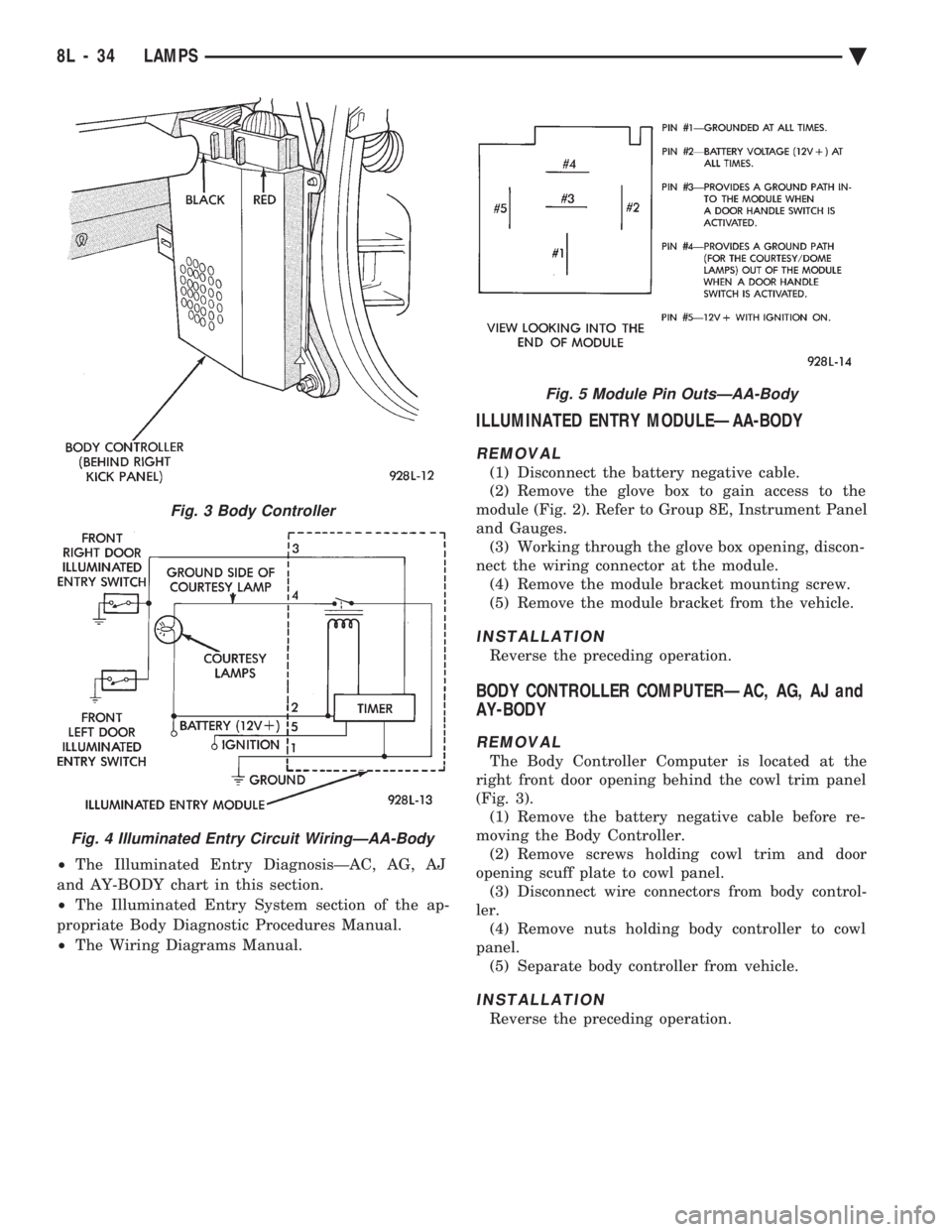
The Body Controller Computer is located at the
right front door opening behind the cowl trim panel
(Fig. 3). (1) Remove the battery negative cable before re-
moving the Body Controller. (2) Remove screws holding cowl trim and door
opening scuff plate to cowl panel. (3) Disconnect wire connectors from body control-
ler. (4) Remove nuts holding body controller to cowl
panel. (5) Separate body controller from vehicle.
INSTALLATION
Reverse the preceding operation.
Fig. 3 Body Controller
Fig. 4 Illuminated Entry Circuit WiringÐAA-Body
Fig. 5 Module Pin OutsÐAA-Body
8L - 34 LAMPS Ä
Page 700 of 2438
(1) Be sure that the module has a battery feed
from the 20 Amp breaker in cavity 1 of the black
connector. Also affected would be the optical horn
and the stop lamps. (2) Be sure that the module has an ignition feed
from 5 Amp fuse in cavity 8 of the black connector.
Also affected would be the body computer, instru-
ment cluster and message center. (3) Be sure that the module has a ground from the
right side cowl behind the body computer to the cav-
ity 5 of the black connector. (4) Be sure that you are supplying a good ground
to the programming wire. (5) If the above circuits are good, replace the Re-
ceiver Module. CONDITION: Doors can be locked or unlocked with
the Keyless Entry transmitter. But the doors will not
lock. The Vehicle Theft Alarm system will not arm,
when using only the power door LOCK switch in the
driver's door. (1) Be sure you have not left key in the ignition
column lock cylinder. (2) If step 1 is OK, check the Key in Lock switch
circuit in the steering column for a short to ground. (3) In this problem the body computer controls the
LOCK function. Be sure that it is providing a battery
voltage output to the door lock relay. The door lock
relay controls the door lock motors. CONDITION: Doors will lock but Vehicle Theft
System will not arm when using the transmitter. (1) The Keyless Entry Receiver Module controls
the door lock signal to the door lock relay. The door
lock relay controls the door lock motors. Check for
battery voltage at cavity 10 of the Theft Alarm mod-
ule from the Receiver module. (2) If voltage is OK, replace Receiver module.
CONDITION: All doors except driver's door will
lock with the transmitter. (1) Test the driver's door output of the Receiver
Module for a ground. (2) If there is no ground at the pin, replace the Re-
ceiver module. (3) If there is a ground at the output, replace the
door lock motor. CONDITION: Only driver's door will lock with the
transmitter.
² Repair ground circuit to unlock relay
² Replace unlock relay
CONDITION: Doors do not lock with the transmit-
ter, but still get horn CHIRP that indicates that they
did lock. Replace Receiver module. CONDITION: Doors will lock with the transmitter
but there is no horn CHIRP. (1) Press horn button, listen horn sound.
(2) If the horn sounded, change horn relay. (3) Still no CHIRP, check continuity between the
horn relay and the receiver output pin. Repair as
necessary. (4) Still no horn CHIRP, replace the receiver mod-
ule. (5) If using a DRB II, refer to Body Diagnostic Pro-
cedures.
REMOTE KEYLESS MODULE REPLACEMENT
(1) Remove lower right instrument panel silencer.
(2) Remove glove box assembly.
(3) Remove three screws attaching the mounting
bracket to instrument panel. (4) Lower bracket and module assembly, to discon-
nect wire connector. (5) Remove two screws attaching the Remote Key-
less entry Module to bracket. (6) Remove two screws attaching the security mod-
ule to bracket. (7) To installation reverse above procedures.
LAMP OUTAGE MODULE REPLACEMENT
(1) Remove lower right instrument panel silencer.
(2) Remove glove box and ash receiver module.
(3) Remove three screws attaching the mounting
bracket to instrument panel. (4) Lower bracket and module assembly, to discon-
nect wire connectors. (5) Remove two screws attaching the Lamp Outage
Module to bracket. (6) Remove two screws attaching the security mod-
ule to bracket. (7) To installation reverse above procedures.
DOOR LOCK INHIBIT
The power door lock inhibit system prevents the
doors from being locked using the power door locks
when either of two conditions occur: (1) The key is in the ignition switch and any of the
doors are open. The ignition switch does not have to
be ON. (2) The key is in the ignition switch and the head-
lamp are on.
AC, AG, AJ AND AY BODIES
With the ignition switch in the ON or OFF position
and the driver's door open the Body Controller will
ignore the command to lock the power door locks.
Once the key is removed, or the driver's door is
closed, the Body Controller will allow the power door
locks to lock. Refer to Body Diagnostic Procedure
Manual for further testing procedures.
8P - 6 POWER LOCKS Ä
Page 702 of 2438
AA BODY
Uses a power door lock inhibit relay. The relay is
located above the glove box compartment.
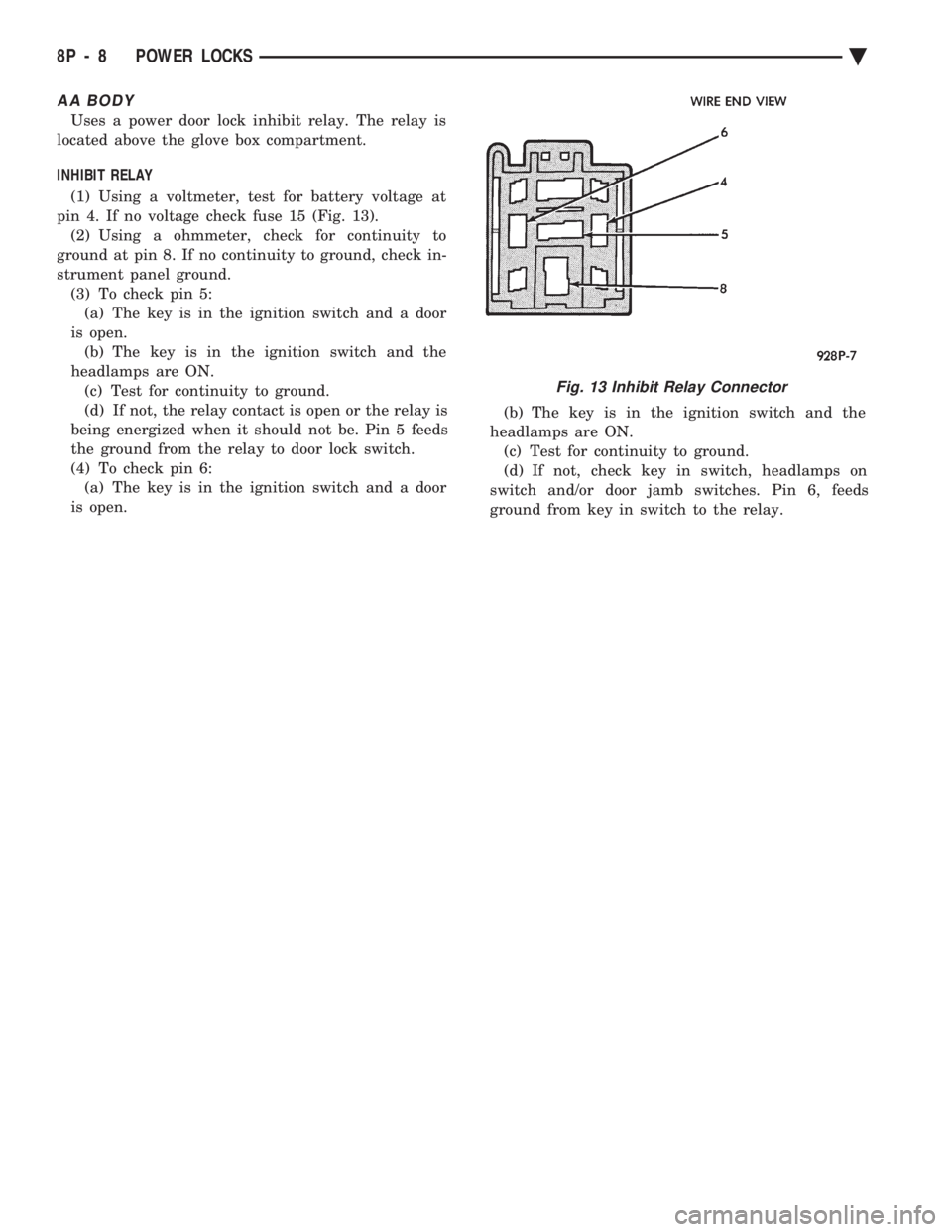
INHIBIT RELAY
(1) Using a voltmeter, test for battery voltage at
pin 4. If no voltage check fuse 15 (Fig. 13). (2) Using a ohmmeter, check for continuity to
ground at pin 8. If no continuity to ground, check in-
strument panel ground. (3) To check pin 5:(a) The key is in the ignition switch and a door
is open. (b) The key is in the ignition switch and the
headlamps are ON. (c) Test for continuity to ground.
(d) If not, the relay contact is open or the relay is
being energized when it should not be. Pin 5 feeds
the ground from the relay to door lock switch.
(4) To check pin 6: (a) The key is in the ignition switch and a door
is open. (b) The key is in the ignition switch and the
headlamps are ON. (c) Test for continuity to ground.
(d) If not, check key in switch, headlamps on
switch and/or door jamb switches. Pin 6, feeds
ground from key in switch to the relay.
Fig. 13 Inhibit Relay Connector
8P - 8 POWER LOCKS Ä
Page 704 of 2438

(3) Activate the power door locks in both the
LOCK and UNLOCK directions. The horn will sound
after each activation. (4) Rotate the key in each of the door lock cylin-
ders to the unlock position. The horn will sound as
the switch closes, and again when it opens. There
must b e a 1 second delay between changing switch
states, or the horn will not sound.
² Press the LOCK button,horn will sound.
² Press the UNLOCK button, horn will sound.
(5) Cycle the key to the ignition RUN position. A
single horn pulse will indicate proper operation of
the ignition input. This will also take the module out
of the diagnostics mode. For any of these tests, if the
switch does not remain open or closed for at least 1
second, the horn will only sound once. The lack of a horn pulse, during any operation, in-
dicates a switch failure. Check for continuity at the
switch, if this is good, check for an open or shorted
wire between the switch and alarm module. Also,
check if a new powertrain control module has been
installed recently. Vehicle Theft Security System will
not function until 20 engine cranks. Whenever a Vehicle Theft Security System mal-
function occurs, first verify that the wire harness is
properly connected to all connectors before starting
normal diagnosis and repair procedures. Refer to Ve-
hicle Theft Security System Diagnosis Chart (Fig. 3).VEHICLE THEFT SECURITY SYSTEM MODULE
REPLACEMENT
If the Vehicle Theft Security System module is be-
ing removed and no replacement module is being in-
stalled, the module wiring must be disconnected
while the engine is running. Failure to do so will
cause a no-start condition (Fig. 3 and 4). (1) Remove lower right instrument panel silencer.
(2) Remove glove box assembly.
(3) Remove three attaching screws mounting the
bracket to instrument panel. (4) Lower bracket and module assembly, to discon-
nect wire connectors. (5) Remove the Remote keyless module so to have
access to the Security Module two screws attaching
module to bracket. (6) For installation reverse above procedures.
SECURITY SYSTEM HOOD SWITCH REPLACEMENT
(1) Remove screw from left inner fender (Fig. 5).
(2) Disconnect wiring.
(3) Remove switch.
(4) For installation reverse above procedures.
SECURITY SYSTEM DOOR SWITCH REPLACEMENT
(1) Remove door trim panel and water shield. Re-
fer to Group 23, Body.
Fig. 1 Vehicle Theft Security System Components
8Q - 2 VEHICLE THEFT SECURITY SYSTEM Ä
Page 749 of 2438

CONDITION: NO TONE WHEN HEADLAMPS ARE ON AND DRIVER'S DOOR IS OPEN, ANDIGNITION IS OFF
PROCEDURE
(1) Check left door jamb switch for good ground
when driver's door is open. This may be checked at
terminal 1 of 25-way body controller connector. (2) Check for battery feed at terminal 16 of 25-way
body controller connector. (3) Check headlamp switch.
CONDITION: NO TONE WHEN KEY IS LEFT INIGNITION AND DRIVER'S DOOR IS OPEN
PROCEDURE
(1) Check left door jamb switch for good ground
when driver's door is open. This may be checked at
terminal 1 of 25-way body controller connector. (2) Check for battery feed at terminal 16 of 25-way
body controller connector. (3) Check key-in switch.
CONDITION: CHIMES CONTINUE WHENHEADLAMPS ARE TURNED OFF AND/OR KEYIS REMOVED FROM IGNITION
PROCEDURE
Check wiring for a grounded condition between
headlamp switch, key-in switch, and body controller.
SERVICE PROCEDURES
CHIME MODULE REPLACEMENT AA and AP
BODIES
(1) Open glove box door and disconnect check strap.
(2) Disconnect glove box light switch.
(3) Remove screws from glove box assembly and
remove. (4) Remove two screws from chime module mount-
ing bracket (Figs. 9 and 10). (5) Disconnect chime module wiring and remove
module. (6) For installation reverse above procedures.
BODY CONTROLLER REPLACEMENT
Refer to Group 8E, Instrument Panel and Gauges.
SEAT BELT BUCKLE REPLACEMENT
Refer to Group 23, Body of this service manual.
HEADLAMP SWITCH REPLACEMENT
Refer to Group 8E, Instrument Panel and Gauges.
KEY-IN SWITCH REPLACEMENT
The Key-in switch is built into the ignition switch as-
sembly. Should the Key-in switch require service, the
ignition switch assembly must be replaced. Refer to
Group 8D Ignition System of this service manual (Fig.
11).
Fig. 9 Chime Module LocationÐAA Body
Fig. 10 Chime Module Location
Fig. 11 Halo Lamp and Key-In Warning Switch Continuity
Ä CHIME WARNING/REMINDER SYSTEM 8U - 5
Page 932 of 2438
Wiring Diagram
Name Sheet Number
Fan Control Relay ...........................33
Radiator Fan Motor ..........................33
Fog Lamps ............................. .55, 56
Fog Lamp Relay .............................48
Fog Lamp Switch .............................48
Front End Lighting ........................ .55, 56
Front Left Side Marker Lamp ....................56
Front Right Side Marker Lamp ...................55
Left Aero Hi-Low Beam Headlamp .................56
Left Fog Lamp .............................56
Left Park & Turn Signal Lamp ...................56
Right Aero Hi-Low Beam Headlamp ................55
Right Fog Lamp ............................55
Right Park & Turn Signal Lamp ..................55
Fuel Injection Ignition System (2.5L) .......12, 13, 14, 15, 16
Automatic Shutdown Relay ......................14
Distributor ................................15
Engine Coolant Sensor ........................15
EVAP/Purge Solenoid .........................13
Exhaust Gas Recirculation Diagnostic Solenoid .........13
Heated Oxygen Sensor ........................12
Idle Air Control Motor .........................12
Ignition Coil ...............................14
Injector ..................................16
MAP Sensor ...............................13
Powertrain Control Module ............12, 13, 14, 15, 16
Throttle Position (Sensor) ......................12
Vehicle Speed Senosr .........................15
Fuel Injection Ignition System Flex Fuel (2.5L Engine) ................ .17, 18, 19, 20, 21, 22
Auto Shutdown Relay ........................20
Distributor ...............................22
Engine Coolant Sensor ........................21
EVAP/Purge Solenoid .........................19
Fuel Sensor ...............................17
Heated Oxygen Sensor ........................18
Idle Air Control Motor ........................18
Ignition Coil ...............................20
Injectors .................................17
MAP Sensor ..............................19
Powertrain Control Module (PCM) . . . .17, 18, 19, 20, 21, 22
Throttle Position (Sensor) ......................18
Vehicle Speed Sensor ........................21
Fuel Injection Ignition System (3.0L) ............. .23, 24, 25, 26, 27, 28, 29, 30, 31
Automatic Shutdown Relay .....................28
Distributor ...............................27
Engine Coolant Sensor ........................27
Exhaust Gas Recirculation Diagnostic Solenoid .........24
EVAP/Purge Solenoid .........................23
Heated Oxygen Sensor ........................24
Idle Air Control Motor ........................30
Injectors .................................26
Ignition Coil ...............................29
MAP Sensor ..............................30
Power Steering Pressure Switch ..................25Wiring Diagram
Name Sheet Number
Powertrain Control Module (PCM) .............. .23, 24, 25, 27, 28, 29, 30, 31
Throttle Position (Sensor) ......................24
Vehicle Speed Sensor ........................28
Fuel Pump Motor .............................69
Fuel Pump Relay .............................70
Fuel Tank Electrical Systems ...................69, 70
Fuel Pump Motor ...........................69
Fuel Pump Relays ...........................70
Fuel Tank Level Gauge Sending Unit ...............69
Fuse Application Chart .....................1,2,3,4
Fuses Fuse 1 ..............................4,80,84
Fuse 2 .............4,5,39,40,53,74,80,84,87,89
Fuse 3 ..............................1,95,99
Fuse 4 ..............................1,95,99
Fuse 5 ...............1,49,51,68,71,72,84,87,89
Fuse 6 ..............................2,65,89
Fuse 7 ..............................3,11,59
Fuse 8 ......................3,11,44,45,47,77
Fuse 9 .........................3,11,68,71,72
Fuse 11 ...............3,9,11,16,22,37,47,60,84
Fuse 12 ...............................1,61
Fuse 14 ...............................2,48
Fuse 15 .......................2,45,47,48,106
Fuse 16 ..........................2,44,45,59
Fuse 18 .............................4,11,64
Fuse 19 .............................4,11,61
Fuse 20 ..........................4,11,87,89
Fuseblock Module & Relay Blank ..................107
Glove Box Lamp and Switch ......................54
Hazard Flasher ..............................61
Headlamp Dimmer Switch .....................1,50
Headlamp, Key-in, Seat Belt Chimes .................45
Headlamp Optical Horn Dimmer Switch .............1,50
Headlamp Switch ...........................1,49
Headlamp and Fog Lamp Switch ..............48, 49, 50
Fog Lamp Relay ............................48
Fog Lamp Switch ...........................48
Headlamp Switch ...........................49
Optical Horn & Headlamp Dimmer Switch ............50
Headlamp Switch Controlled Interior Lighting .........51, 52
A/C Lamps ...............................52
Ash Receiver Lamp ..........................52
Cigar Lighter Lamp ..........................52
Heater Lamp ..............................52
Radio Lamp ...............................52
Heated Oxygen Sensor ................... .12, 18, 24
Heated Rear Window ..........................84
Heated Rear Window .........................84
Switch ..................................84
Timer ...................................84
Heater System ...............................68
Bi-level Control Switch ........................68
Blower Motor ..............................68
Blower Slide Control .........................68
Heater Control Switch ........................68
8W - 182 WIRING DIAGRAMS AA-BODY Ä