1993 CHEVROLET PLYMOUTH ACCLAIM glove box
[x] Cancel search: glove boxPage 533 of 2438
(4) Remove panel top cover by pushing forward
and prying up, using a straight edge to assist in the
removal. (5) Disconnect bulkhead connector at brace under
instrument panel at left side. (6) Remove glovebox/ash receiver module and right
instrument panel silencer. (7) Remove center panel support brace and air bag
diagnostic module assembly. (8) Disconnect wiring to airbag module.
(9) Remove upper and lower cluster bezels.
(10) Remove steering column cover.
(11) Remove steering column mounting nuts and
lower steering column. (12) Unhook shift indicator cable eyelet from steer-
ing column actuator. (13) Unlatch lock tab in shift indicator column in-
sert and squeeze legs together to remove from steer-
ing column. (14) Remove cluster assembly while guiding trans-
mission range indicator guide tube through access
hole in the base panel. (15) Remove instrument panel steering column
opening support/hood release handle assembly. (16) Remove two steering column upper studs and
loosen side cowl tie-down bolts. (17) Remove steering column tilt lever.
(18) Remove upper and lower lock housing shroud.
(19) Remove lower fixed shroud.
(20) Remove upper fixed shroud (snaps in place).
(21) Disconnect airbag pigtail, ignition switch and
halo light/key buzzer switch wiring. (22) Disconnect Multi-function switch by loosening
connector jack screw and pulling connector from
switch. (23) Disconnect airbag pigtail from wiring trough
housing by pulling two push fasteners. (24) Remove wiring trough from steering column.
(25) Remove defroster ducts.
(26) Remove five screws along fence line and roll
panel down, attach a hook to hold in position. (27) Open hood and remove plenum grill.
(28) Disconnect washer bottle, resistor block and
under hood lamp wiring. Washer bottle must be re-
moved to gain access. (29) Remove grommet and pull plenum wiring into
vehicle through plenum panel. (30) Disconnect right demister hose from instru-
ment panel. (31) Disconnect antenna cable.
(32) Disconnect right and left 25 way body wiring
connectors. (33) Disconnect A/C heater control cables, wiring
connectors and vacuum harness. (34) Remove right side panel ground wire.
(35) Disconnect body controller wiring.
(36) Remove instrument panel assembly from vehi-
cle. (37) For installation reverse above procedures.
INTERIOR LAMP REPLACEMENT
The reading, overhead console and door lamps op-
erate when the doors are open or headlamp switch is
placed in courtesy position. Front overhead lamps re-
fer to Group 8C, Overhead Console.
TRUNK LAMP
The lamp has easily accessible without removing
components.
DOOR LAMP
Pry along the forward edge of the lens and pivot
lens out of the door trim panel. Remove lamp. To re-
move lamp housing, remove door trim panel. Refer to
Group 23, Body. Disconnect all wiring. Remove
screws, if so equipped securing lamp housing to trim
panel, and replace housing.
CÐPILLAR READING/COURTESY LAMP
Pry along the rearward edge of the lamp and pivot
lamp out from quarter trim panel. Disconnect wiring
and remove lamp cover. Replace lamp. The lamp operates when the doors are open or the
headlamp switch is turned to the courtesy mode. The
lamp will function as a reading lamp when the doors
are closed and the button switch on the lamp is de-
pressed.
ROOF RAIL READING
Pry along the bottom edge of the lens and pivot
lens out. Replace lamp. To remove the lamp, remove
the screw which retains the coat hook. Remove the
garnish molding. Disconnect the wiring harness. Re-
move the two clips which retain the lamp to the
molding. Replace lamp. The lamp operates like the
C-pillar reading/courtesy lamp.
Ä INSTRUMENT PANEL AND GAUGES 8E - 41
Page 546 of 2438

INSTALLATION (1) Latch switch linkage in the up position.
(2) Insert dimmer shaft into dimmer knob while
aligning switch in to switch pod assembly. (3) Install switch attaching screws.
(4) Unlatch linkage and install onto push buttons.
(5) Operate all switch modes for correct operation.
(6) Install turn signal switch.
(7) Reconnect wiring for turn signal switch, mak-
ing sure wire is properly clipped into position. (8) Place together the inner and outer bezels. In-
stall five inner switch pod panel screws and three
screws from underneath the switch pod. (9) Install turn signal lever by pushing straight
into switch assembly. (10) Install switch pod assembly.
LOWER STEERING COLUMN COVER REMOVAL
(1) Remove screws along top edge of cover.
(2) Remove screw at each lower corner of cover. (3) Remove cover from underneath over column
cover. (4) For installation reverse above procedures.
GLOVEBOX MODULE REMOVAL
(1) Disconnect battery negative cable and isolate
or remove fuse #26 prior to removing switch or wires
may short to ground. (2) Remove cowl side trim panel.
(3) Remove screws at right end of glovebox and
lower corners. (4) Open glovebox, remove light and disconnect
wiring. (5) Remove five screws along top of glovebox frame
and screw at each lower corner. (6) Remove glovebox assembly.
(7) For installation reverse above procedures.
CONCEALED HEADLAMP MODULE REMOVAL
(1) Remove left under panel silencer.
(2) Slide module off bayonet bracket while disen-
gaging spring retainer. (3) Disconnect wiring terminal.
(4) For installation reverse above procedures.
HOOD RELEASE REMOVE
(1) Remove lower column cover.
(2) Remove screws on fuse block and move aside.
(3) Remove screws on hood release assembly to re-
move. (4) For installation reverse above procedures.
AIR CONDITIONING CONTROL REMOVE
(1) Remove center stack bezel.
(2) Remove two control mounting screws (Fig. 28
and 29).
(3) Slide control rearward, disconnect cable, vac-
uum harness, and electrical wiring. With automatic
temperature control, disconnect wiring connector; be-
ing careful not to break off locking tab. (4) For installation reverse above procedures.
Fig. 26 Switch Pod Assembly
Fig. 27 Headlamp Multi-Function Switch
Fig. 28 A/C Control
8E - 54 INSTRUMENT PANEL AND GAUGES Ä
Page 547 of 2438
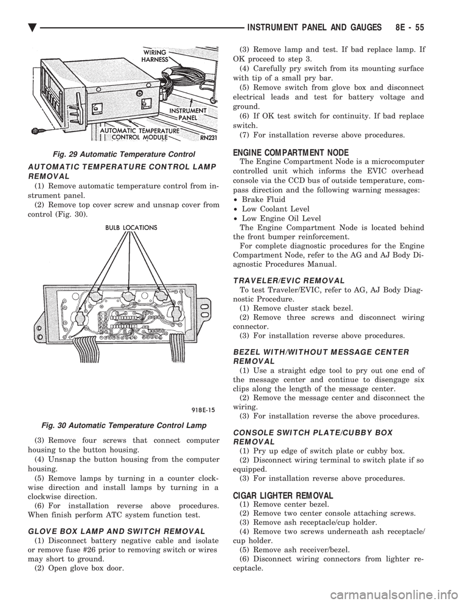
AUTOMATIC TEMPERATURE CONTROL LAMP REMOVAL
(1) Remove automatic temperature control from in-
strument panel. (2) Remove top cover screw and unsnap cover from
control (Fig. 30).
(3) Remove four screws that connect computer
housing to the button housing. (4) Unsnap the button housing from the computer
housing. (5) Remove lamps by turning in a counter clock-
wise direction and install lamps by turning in a
clockwise direction. (6) For installation reverse above procedures.
When finish perform ATC system function test.
GLOVE BOX LAMP AND SWITCH REMOVAL
(1) Disconnect battery negative cable and isolate
or remove fuse #26 prior to removing switch or wires
may short to ground. (2) Open glove box door. (3) Remove lamp and test. If bad replace lamp. If
OK proceed to step 3. (4) Carefully pry switch from its mounting surface
with tip of a small pry bar. (5) Remove switch from glove box and disconnect
electrical leads and test for battery voltage and
ground. (6) If OK test switch for continuity. If bad replace
switch. (7) For installation reverse above procedures.
ENGINE COMPARTMENT NODE
The Engine Compartment Node is a microcomputer
controlled unit which informs the EVIC overhead
console via the CCD bus of outside temperature, com-
pass direction and the following warning messages:
² Brake Fluid
² Low Coolant Level
² Low Engine Oil Level
The Engine Compartment Node is located behind
the front bumper reinforcement. For complete diagnostic procedures for the Engine
Compartment Node, refer to the AG and AJ Body Di-
agnostic Procedures Manual.
TRAVELER/EVIC REMOVAL
To test Traveler/EVIC, refer to AG, AJ Body Diag-
nostic Procedure. (1) Remove cluster stack bezel.
(2) Remove three screws and disconnect wiring
connector. (3) For installation reverse above procedures.
BEZEL WITH/WITHOUT MESSAGE CENTERREMOVAL
(1) Use a straight edge tool to pry out one end of
the message center and continue to disengage six
clips along the length of the message center. (2) Remove the message center and disconnect the
wiring. (3) For installation reverse the above procedures.
CONSOLE SWITCH PLATE/CUBBY BOXREMOVAL
(1) Pry up edge of switch plate or cubby box.
(2) Disconnect wiring terminal to switch plate if so
equipped. (3) For installation reverse above procedures.
CIGAR LIGHTER REMOVAL
(1) Remove center bezel.
(2) Remove two center console attaching screws.
(3) Remove ash receptacle/cup holder.
(4) Remove two screws underneath ash receptacle/
cup holder. (5) Remove ash receiver/bezel.
(6) Disconnect wiring connectors from lighter re-
ceptacle.
Fig. 29 Automatic Temperature Control
Fig. 30 Automatic Temperature Control Lamp
Ä INSTRUMENT PANEL AND GAUGES 8E - 55
Page 549 of 2438
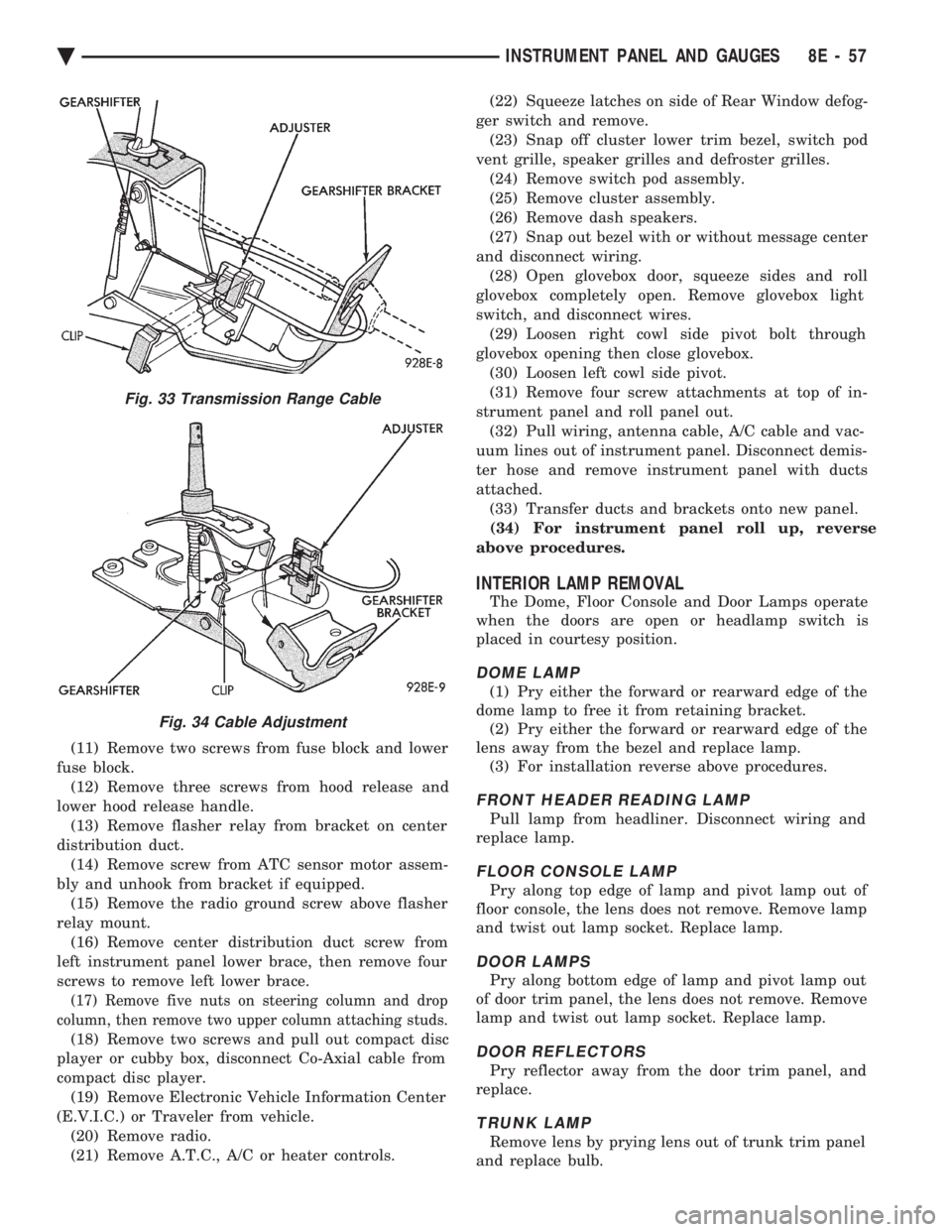
(11) Remove two screws from fuse block and lower
fuse block. (12) Remove three screws from hood release and
lower hood release handle. (13) Remove flasher relay from bracket on center
distribution duct. (14) Remove screw from ATC sensor motor assem-
bly and unhook from bracket if equipped. (15) Remove the radio ground screw above flasher
relay mount. (16) Remove center distribution duct screw from
left instrument panel lower brace, then remove four
screws to remove left lower brace.
(17) Remove five nuts on steering column and drop
column, then remove two upper column attaching studs.
(18) Remove two screws and pull out compact disc
player or cubby box, disconnect Co-Axial cable from
compact disc player. (19) Remove Electronic Vehicle Information Center
(E.V.I.C.) or Traveler from vehicle. (20) Remove radio.
(21) Remove A.T.C., A/C or heater controls. (22) Squeeze latches on side of Rear Window defog-
ger switch and remove. (23) Snap off cluster lower trim bezel, switch pod
vent grille, speaker grilles and defroster grilles. (24) Remove switch pod assembly.
(25) Remove cluster assembly.
(26) Remove dash speakers.
(27) Snap out bezel with or without message center
and disconnect wiring. (28) Open glovebox door, squeeze sides and roll
glovebox completely open. Remove glovebox light
switch, and disconnect wires. (29) Loosen right cowl side pivot bolt through
glovebox opening then close glovebox. (30) Loosen left cowl side pivot.
(31) Remove four screw attachments at top of in-
strument panel and roll panel out. (32) Pull wiring, antenna cable, A/C cable and vac-
uum lines out of instrument panel. Disconnect demis-
ter hose and remove instrument panel with ducts
attached. (33) Transfer ducts and brackets onto new panel.
(34) For instrument panel roll up, reverse
above procedures.
INTERIOR LAMP REMOVAL
The Dome, Floor Console and Door Lamps operate
when the doors are open or headlamp switch is
placed in courtesy position.
DOME LAMP
(1) Pry either the forward or rearward edge of the
dome lamp to free it from retaining bracket. (2) Pry either the forward or rearward edge of the
lens away from the bezel and replace lamp. (3) For installation reverse above procedures.
FRONT HEADER READING LAMP
Pull lamp from headliner. Disconnect wiring and
replace lamp.
FLOOR CONSOLE LAMP
Pry along top edge of lamp and pivot lamp out of
floor console, the lens does not remove. Remove lamp
and twist out lamp socket. Replace lamp.
DOOR LAMPS
Pry along bottom edge of lamp and pivot lamp out
of door trim panel, the lens does not remove. Remove
lamp and twist out lamp socket. Replace lamp.
DOOR REFLECTORS
Pry reflector away from the door trim panel, and
replace.
TRUNK LAMP
Remove lens by prying lens out of trunk trim panel
and replace bulb.
Fig. 33 Transmission Range Cable
Fig. 34 Cable Adjustment
Ä INSTRUMENT PANEL AND GAUGES 8E - 57
Page 561 of 2438
HEATER CONTROL LAMP REPLACEMENT
(1) Remove heater control. Refer to A/C Heater
Control for removal. (2) Pull control far enough to gain access to the
lamp socket. (3) Replace lamp. To remove lamp rotate socket
counter clockwise. To install rotate clockwise. (4) For installation reverse above procedures.
A/C CONTROL LAMP REPLACEMENT
(1) Remove heater control. Refer to A/C Heater
Control for removal. (2) Pry temperature and blower switch knobs off
with flat blade tool. To protect cosmetic face place
cardboard or similar material on the face plate while
prying. (3) Remove face plate by lifting on the six tabs.
Three on top and three on bottom of the face plate. (4) Replace lamp.
(5) For installation reverse above procedures.
HEATER CONTROL BLOWER SWITCHREPLACEMENT
(1) Remove heater control. Refer to A/C Heater
Control for removal. (2) Pry temperature and blower switch knobs off
with flat blade tool. To protect cosmetic face place
cardboard or similar material on the face plate while
prying. (3) Remove face plate by lifting on the six tabs.
Three on top and three on bottom of the face plate. (4) Pry blower switch off with flat blade tool. To
protect cosmetic face, place cardboard or similar ma-
terial on the face plate while prying. (5) To replace, line up blower switch terminals and
press firmly until the it bottoms out on the housing. (6) For installation reverse above procedures.
A/C CONTROL BLOWER SWITCHREPLACEMENT
(1) Remove heater control. Refer to A/C Heater
Control for removal. (2) Position the temperature knob at the maximum
heat position to gain screw access. (3) Remove two screws holding the blower switch
located on top of the control. (4) Pry the blower switch off with a flat blade tool.
(5) To replace, line up blower switch terminals and
press firmly until the it bottoms out on the housing. (6) For installation reverse above procedures.
GLOVE BOX MODULE REPLACEMENT
(1) Disconnect battery negative cable and isolate
or remove fuse #13 prior to removing switch or wires
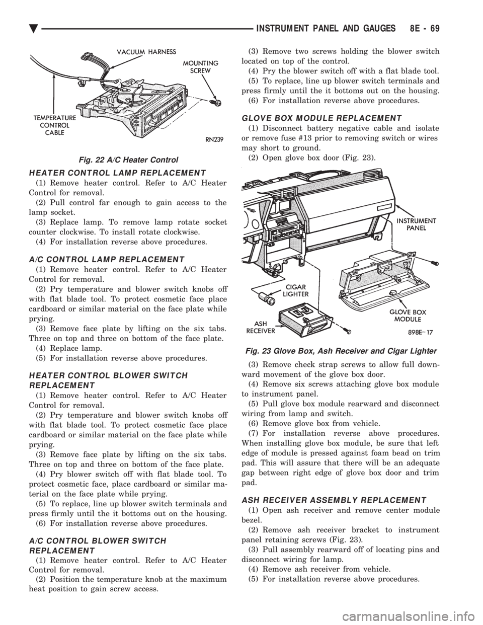
may short to ground. (2) Open glove box door (Fig. 23).
(3) Remove check strap screws to allow full down-
ward movement of the glove box door. (4) Remove six screws attaching glove box module
to instrument panel. (5) Pull glove box module rearward and disconnect
wiring from lamp and switch. (6) Remove glove box from vehicle.
(7) For installation reverse above procedures.
When installing glove box module, be sure that left
edge of module is pressed against foam bead on trim
pad. This will assure that there will be an adequate
gap between right edge of glove box door and trim
pad.
ASH RECEIVER ASSEMBLY REPLACEMENT
(1) Open ash receiver and remove center module
bezel. (2) Remove ash receiver bracket to instrument
panel retaining screws (Fig. 23). (3) Pull assembly rearward off of locating pins and
disconnect wiring for lamp. (4) Remove ash receiver from vehicle.
(5) For installation reverse above procedures.
Fig. 22 A/C Heater Control
Fig. 23 Glove Box, Ash Receiver and Cigar Lighter
Ä INSTRUMENT PANEL AND GAUGES 8E - 69
Page 562 of 2438

CIGAR LIGHTER REPLACEMENT
(1) Remove center bezel assembly (Fig. 23).
(2) Remove center module lower cover or open for-
ward console lid. (3) Unscrew lighter receptacle shell from recepta-
cle and remove from base instrument panel. (4) Disconnect wiring connectors from lighter re-
ceptacle and remove from vehicle. (5) For installation reverse above procedures.
REAR WINDOW DEFOGGER AND/OR FOG LAMP SWITCH REPLACEMENT
(1) Remove center module bezel assembly (Fig. 20).
(2) Remove two switch bezel screws (Fig. 24).
(3) Pull switches and bezel rearward and discon-
nect wiring connector. (4) Remove two switch retaining screws.
(5) Remove switch from bezel.
(6) For installation reverse above procedures.
INTERMITTENT WIPE MODULE REPLACEMENT
(1) Remove lower steering column cover.
(2) Slide intermittent wipe module off of bracket
located on steering column reinforcement (Fig. 25). (3) Disconnect wiring connector from module and
remove module from vehicle. (4) For installation reverse above procedures.
GLOVE BOX LAMP AND SWITCHREPLACEMENT
(1) Disconnect battery and/or pull fuse # 13 before
starting removal procedure. (2) Open glove box door (Fig. 26).
(3) Carefully pry lamp from its mounting surface
with tip of a small screwdriver. (4) Pull lamp from box and disconnect electrical
leads. (5) Remove lamp.
(6) For installation reverse above procedures.
CONSOLETTE ASSEMBLY REPLACEMENT
(1) Remove shifter handle.
(2) Unsnap transmission range indicator bezel or
shift boot bezel from consolette, disconnect wiring
and remove bezel assembly (Fig. 27). (3) Remove two screws from side of armrest.
(4) Remove four caps which cover attaching
screws. (5) Remove four attaching screws.
(6) Lift consolette up and over shift mechanism to
remove. (7) For installation reverse above procedures.
Fig. 24 Rear Window Defogger and Fog Lamp Switch
Fig. 25 Intermittent Wipe Module
Fig. 26 Glove Box Lamp and Switch
8E - 70 INSTRUMENT PANEL AND GAUGES Ä
Page 564 of 2438
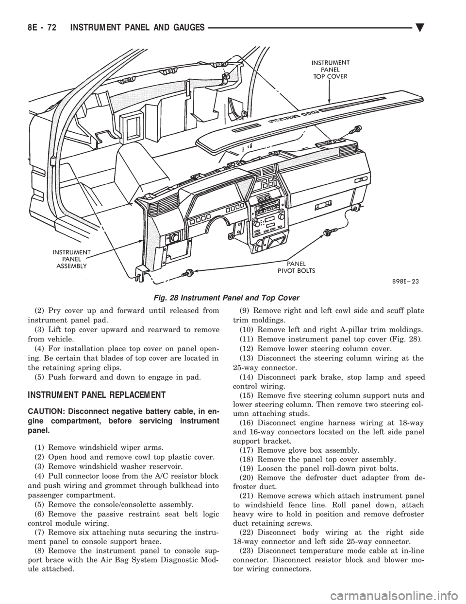
(2) Pry cover up and forward until released from
instrument panel pad. (3) Lift top cover upward and rearward to remove
from vehicle. (4) For installation place top cover on panel open-
ing. Be certain that blades of top cover are located in
the retaining spring clips. (5) Push forward and down to engage in pad.
INSTRUMENT PANEL REPLACEMENT
CAUTION: Disconnect negative battery cable, in en-
gine compartment, before servicing instrument
panel.
(1) Remove windshield wiper arms.
(2) Open hood and remove cowl top plastic cover.
(3) Remove windshield washer reservoir.
(4) Pull connector loose from the A/C resistor block
and push wiring and grommet through bulkhead into
passenger compartment. (5) Remove the console/consolette assembly.
(6) Remove the passive restraint seat belt logic
control module wiring. (7) Remove six attaching nuts securing the instru-
ment panel to console support brace. (8) Remove the instrument panel to console sup-
port brace with the Air Bag System Diagnostic Mod-
ule attached. (9) Remove right and left cowl side and scuff plate
trim moldings. (10) Remove left and right A-pillar trim moldings.
(11) Remove instrument panel top cover (Fig. 28).
(12) Remove lower steering column cover.
(13) Disconnect the steering column wiring at the
25-way connector. (14) Disconnect park brake, stop lamp and speed
control wiring. (15) Remove five steering column support nuts and
lower steering column. Then remove two steering col-
umn attaching studs. (16) Disconnect engine harness wiring at 18-way
and 16-way connectors located on the left side panel
support bracket. (17) Remove glove box assembly.
(18) Remove the panel top cover assembly.
(19) Loosen the panel roll-down pivot bolts.
(20) Remove the defroster duct adapter from de-
froster duct. (21) Remove screws which attach instrument panel
to windshield fence line. Roll panel down, attach
heavy wire to hold in position and remove defroster
duct retaining screws. (22) Disconnect body wiring at the right side
18-way connector and left side 25-way connector. (23) Disconnect temperature mode cable at in-line
connector. Disconnect resistor block and blower mo-
tor wiring connectors.
Fig. 28 Instrument Panel and Top Cover
8E - 72 INSTRUMENT PANEL AND GAUGES Ä
Page 595 of 2438

² If no short to ground at connector, check speaker
resistance at amplifier connector for an reading of
three to five ohms.
² If resistance is OK, refer to Radio Diagnosis. If ra-
dio checks OK, replace amplifier.
² If resistance is less than three ohms check
speaker. Check across the speaker connector if less
than three ohms replace speaker. If resistance is OK
repair wires
CONDITION: MECHANICAL NOISE DISTORTION
² Check trim for loose parts and speaker attach-
ments for buzzes
² Remove speaker still connected and listen for dis-
tortion. Distortion replace speaker.
CONDITION: ONE SPEAKER NON-OPERATIVE
² Remove output signal connector from amplifier
and check for three to five ohms resistance to the
non-operative speaker. Refer to Fig. 34 for the appro-
priate pin numbers.
² If resistance is less than three ohms, test speaker
for resistance.
² If OK repair wire. If not replace speaker.
CONDITION: ALL SPEAKERS NON-OPERATIVE
²Check radio for being ON, are the display lights
on
² Radio not ON, refer to Radio Diagnosis
² Check Amplifier Connectors and wires for proper
connection
² Check pin 9 and pin 27 for battery voltage
² If voltage OK replace amplifier ²
If pin 27 has battery voltage and pin 9 has 0 volt-
age. Refer to Power Antenna Diagnosis and test volt-
age at antenna relay.
² If pin 9 has battery voltage and pin 27 has 0 volt-
age. Check pin 27 for short to ground.
² If shorted to ground repair wire
² If no short to ground check fuse cavity number 16
for blown fuse.
² If fuse blows again replace amplifier
RELAY/CHOKEÐINFINITY SPEAKER
If the audio system is lacking bass, check for con-
tinuity across the relay and choke connectors. If no
continuity, replace relay/choke assembly (Fig. 35).
LOCATION
(1) AA and AP Bodies, attached to the reinforce-
ment above glove box. (2) AG Body, attached to the dimmer module bay-
onet bracket on the bulkhead behind the glove box.
Fig. 35 Relay/Choke Assembly
Ä AUDIO SYSTEM 8F - 29