1993 CHEVROLET PLYMOUTH ACCLAIM gas type
[x] Cancel search: gas typePage 1634 of 2438
shaped and provides the same spring tension as
longer springs. Valve spring retainers, locks and
seals are conventional.INTAKE MANIFOLD: The aluminum alloy man-
ifold is a cross type with long runners to improve in-
ertia. The runners, attaching below at the cylinder
head, also attach above and support an air plenum.
The air plenum chamber absorbs air pulsations cre-
ated during the suction phase of each cylinder. EXHAUST MANIFOLDS: Both manifolds are a
log style made of ductile cast iron. Exhaust gasses,
collected from the front cylinder bank, leave the
front manifold through an end outlet and are fed
through an upper crossover tube to the rear mani-
fold. The collected exhaust from both manifolds are
combined, and exit to the exhaust pipe through an
articulated joint. ENGINE LUBRICATION: System is a full flow
filtration, pressure feed type. The oil pump is
mounted in the chaincase cover. The pump inner ro-
tor is driven by the crankshaft. The engine oil pan
contains a baffle plate to control oil level fluctuation
during engine operation.ENGINE MOUNTS
REMOVAL AND INSTALLATION
RIGHT SIDE MOUNT
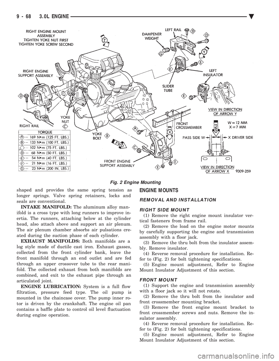
(1) Remove the right engine mount insulator ver-
tical fasteners from frame rail. (2) Remove the load on the engine motor mounts
by carefully supporting the engine and transmission
assembly with a floor jack. (3) Remove the thru bolt from the insulator assem-
bly. Remove insulator. (4) Reverse removal procedure for installation. Re-
fer to (Fig. 2) for bolt tightening specifications. (5) Engine mount adjustment, Refer to Engine
Mount Insulator Adjustment of this section.
FRONT MOUNT
(1) Support the engine and transmission assembly
with a floor jack so it will not rotate. (2) Remove the thru bolt from the insulator and
front crossmember mounting bracket. (3) Remove the front engine mount bracket to
front crossmember screws and nuts. Remove the in-
sulator assembly. (4) Reverse removal procedure for installation. Re-
fer to (Fig. 2) for bolt tightening specifications. (5) Engine mount adjustment, Refer to Engine
Mount Insulator Adjustment of this section.
Fig. 2 Engine Mounting
9 - 68 3.0L ENGINE Ä
Page 1665 of 2438
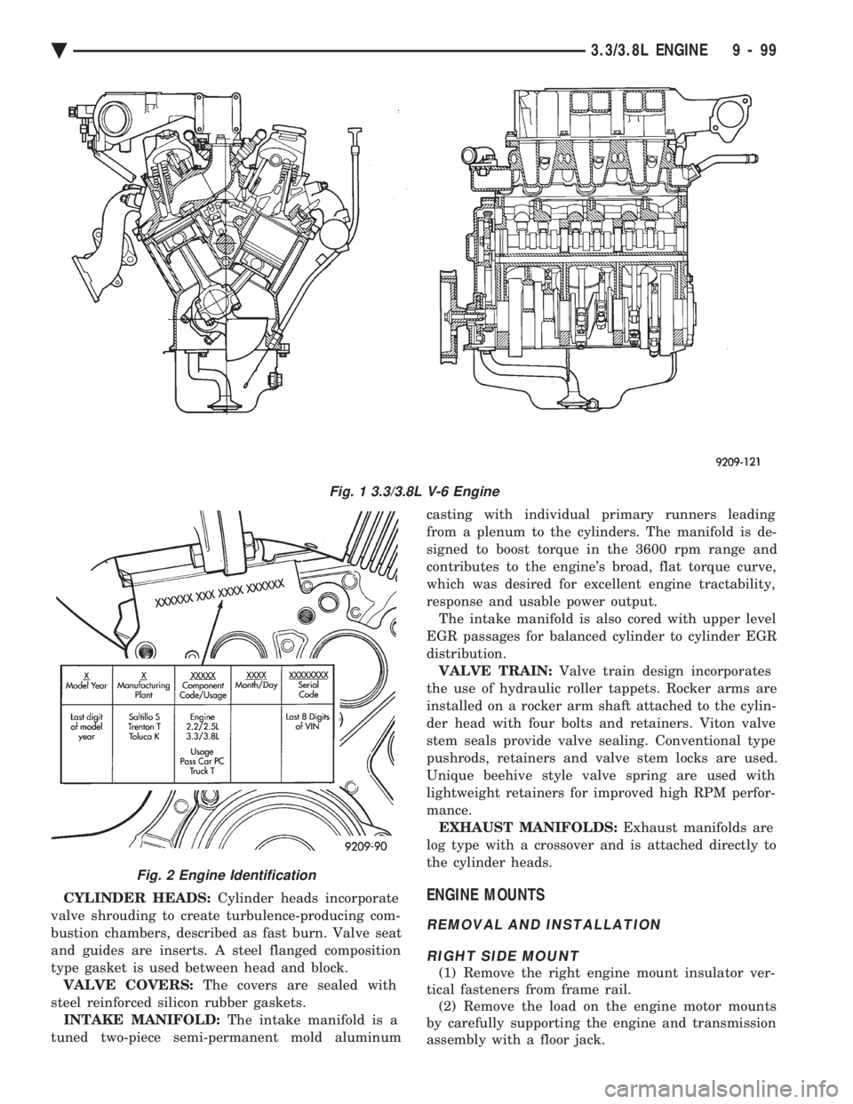
CYLINDER HEADS: Cylinder heads incorporate
valve shrouding to create turbulence-producing com-
bustion chambers, described as fast burn. Valve seat
and guides are inserts. A steel flanged composition
type gasket is used between head and block. VALVE COVERS: The covers are sealed with
steel reinforced silicon rubber gaskets. INTAKE MANIFOLD: The intake manifold is a
tuned two-piece semi-permanent mold aluminum casting with individual primary runners leading
from a plenum to the cylinders. The manifold is de-
signed to boost torque in the 3600 rpm range and
contributes to the engine's broad, flat torque curve,
which was desired for excellent engine tractability,
response and usable power output. The intake manifold is also cored with upper level
EGR passages for balanced cylinder to cylinder EGR
distribution. VALVE TRAIN: Valve train design incorporates
the use of hydraulic roller tappets. Rocker arms are
installed on a rocker arm shaft attached to the cylin-
der head with four bolts and retainers. Viton valve
stem seals provide valve sealing. Conventional type
pushrods, retainers and valve stem locks are used.
Unique beehive style valve spring are used with
lightweight retainers for improved high RPM perfor-
mance. EXHAUST MANIFOLDS: Exhaust manifolds are
log type with a crossover and is attached directly to
the cylinder heads.ENGINE MOUNTS
REMOVAL AND INSTALLATION
RIGHT SIDE MOUNT
(1) Remove the right engine mount insulator ver-
tical fasteners from frame rail. (2) Remove the load on the engine motor mounts
by carefully supporting the engine and transmission
assembly with a floor jack.
Fig. 1 3.3/3.8L V-6 Engine
Fig. 2 Engine Identification
Ä 3.3/3.8L ENGINE 9 - 99
Page 1688 of 2438
ENGINE LUBRICATION SYSTEM
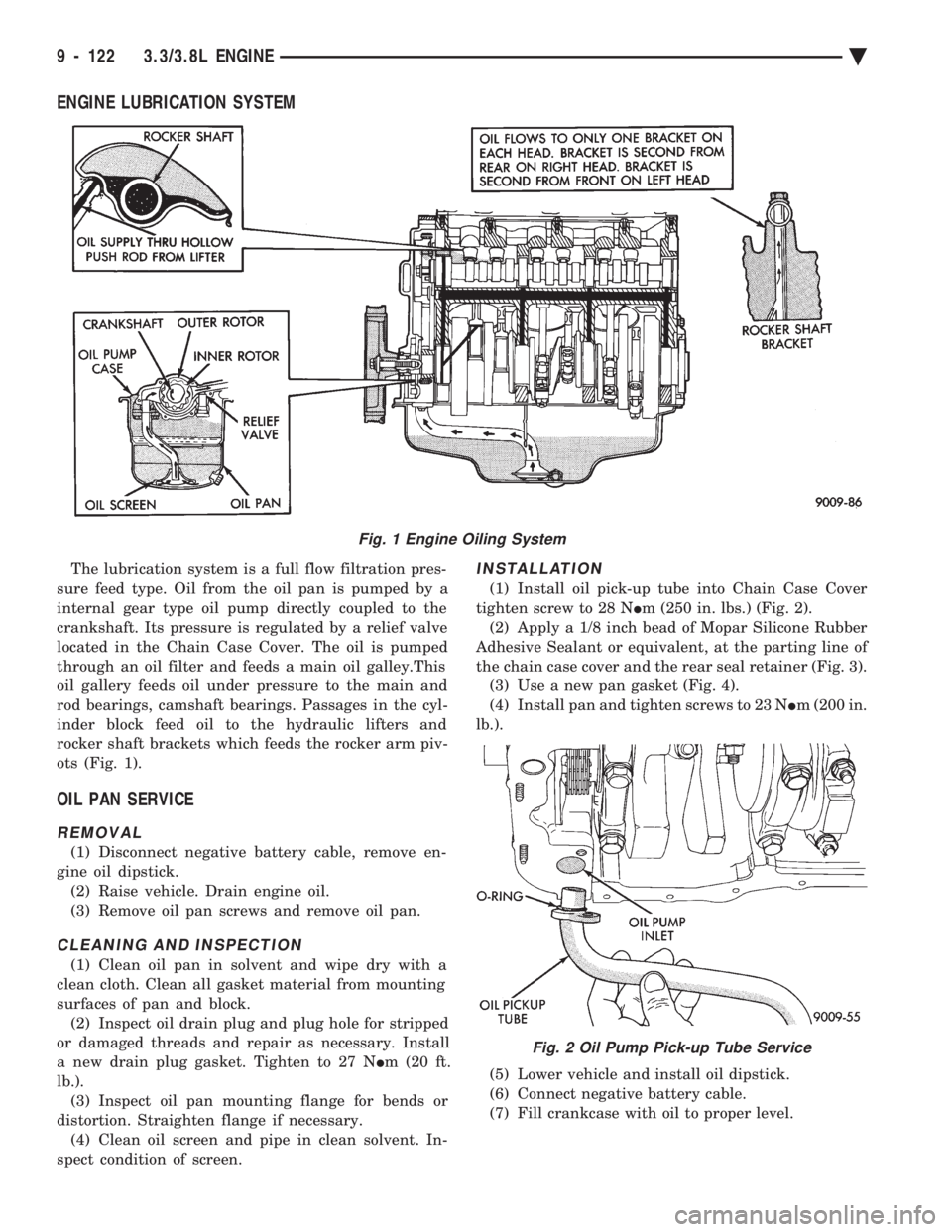
The lubrication system is a full flow filtration pres-
sure feed type. Oil from the oil pan is pumped by a
internal gear type oil pump directly coupled to the
crankshaft. Its pressure is regulated by a relief valve
located in the Chain Case Cover. The oil is pumped
through an oil filter and feeds a main oil galley.This
oil gallery feeds oil under pressure to the main and
rod bearings, camshaft bearings. Passages in the cyl-
inder block feed oil to the hydraulic lifters and
rocker shaft brackets which feeds the rocker arm piv-
ots (Fig. 1).
OIL PAN SERVICE
REMOVAL
(1) Disconnect negative battery cable, remove en-
gine oil dipstick. (2) Raise vehicle. Drain engine oil.
(3) Remove oil pan screws and remove oil pan.
CLEANING AND INSPECTION
(1) Clean oil pan in solvent and wipe dry with a
clean cloth. Clean all gasket material from mounting
surfaces of pan and block. (2) Inspect oil drain plug and plug hole for stripped
or damaged threads and repair as necessary. Install
a new drain plug gasket. Tighten to 27 N Im (20 ft.
lb.). (3) Inspect oil pan mounting flange for bends or
distortion. Straighten flange if necessary. (4) Clean oil screen and pipe in clean solvent. In-
spect condition of screen.
INSTALLATION
(1) Install oil pick-up tube into Chain Case Cover
tighten screw to 28 N Im (250 in. lbs.) (Fig. 2).
(2) Apply a 1/8 inch bead of Mopar Silicone Rubber
Adhesive Sealant or equivalent, at the parting line of
the chain case cover and the rear seal retainer (Fig. 3). (3) Use a new pan gasket (Fig. 4).
(4) Install pan and tighten screws to 23 N Im (200 in.
lb.).
(5) Lower vehicle and install oil dipstick.
(6) Connect negative battery cable.
(7) Fill crankcase with oil to proper level.
Fig. 1 Engine Oiling System
Fig. 2 Oil Pump Pick-up Tube Service
9 - 122 3.3/3.8L ENGINE Ä
Page 1709 of 2438
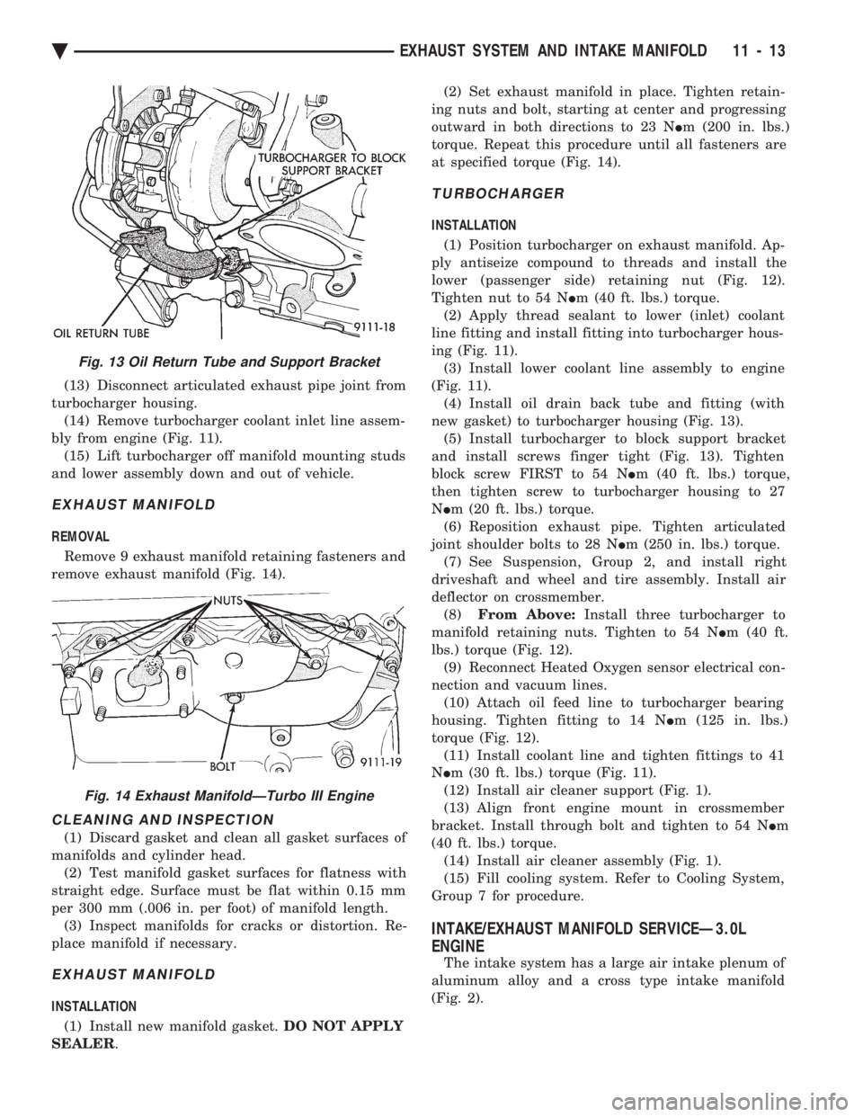
(13) Disconnect articulated exhaust pipe joint from
turbocharger housing. (14) Remove turbocharger coolant inlet line assem-
bly from engine (Fig. 11). (15) Lift turbocharger off manifold mounting studs
and lower assembly down and out of vehicle.
EXHAUST MANIFOLD
REMOVAL
Remove 9 exhaust manifold retaining fasteners and
remove exhaust manifold (Fig. 14).
CLEANING AND INSPECTION
(1) Discard gasket and clean all gasket surfaces of
manifolds and cylinder head. (2) Test manifold gasket surfaces for flatness with
straight edge. Surface must be flat within 0.15 mm
per 300 mm (.006 in. per foot) of manifold length. (3) Inspect manifolds for cracks or distortion. Re-
place manifold if necessary.
EXHAUST MANIFOLD
INSTALLATION
(1) Install new manifold gasket. DO NOT APPLY
SEALER . (2) Set exhaust manifold in place. Tighten retain-
ing nuts and bolt, starting at center and progressing
outward in both directions to 23 N Im (200 in. lbs.)
torque. Repeat this procedure until all fasteners are
at specified torque (Fig. 14).
TURBOCHARGER
INSTALLATION
(1) Position turbocharger on exhaust manifold. Ap-
ply antiseize compound to threads and install the
lower (passenger side) retaining nut (Fig. 12).
Tighten nut to 54 N Im (40 ft. lbs.) torque.
(2) Apply thread sealant to lower (inlet) coolant
line fitting and install fitting into turbocharger hous-
ing (Fig. 11). (3) Install lower coolant line assembly to engine
(Fig. 11). (4) Install oil drain back tube and fitting (with
new gasket) to turbocharger housing (Fig. 13). (5) Install turbocharger to block support bracket
and install screws finger tight (Fig. 13). Tighten
block screw FIRST to 54 N Im (40 ft. lbs.) torque,
then tighten screw to turbocharger housing to 27
N Im (20 ft. lbs.) torque.
(6) Reposition exhaust pipe. Tighten articulated
joint shoulder bolts to 28 N Im (250 in. lbs.) torque.
(7) See Suspension, Group 2, and install right
driveshaft and wheel and tire assembly. Install air
deflector on crossmember. (8) From Above: Install three turbocharger to
manifold retaining nuts. Tighten to 54 N Im (40 ft.
lbs.) torque (Fig. 12). (9) Reconnect Heated Oxygen sensor electrical con-
nection and vacuum lines. (10) Attach oil feed line to turbocharger bearing
housing. Tighten fitting to 14 N Im (125 in. lbs.)
torque (Fig. 12). (11) Install coolant line and tighten fittings to 41
N Im (30 ft. lbs.) torque (Fig. 11).
(12) Install air cleaner support (Fig. 1).
(13) Align front engine mount in crossmember
bracket. Install through bolt and tighten to 54 N Im
(40 ft. lbs.) torque. (14) Install air cleaner assembly (Fig. 1).
(15) Fill cooling system. Refer to Cooling System,
Group 7 for procedure.
INTAKE/EXHAUST MANIFOLD SERVICEÐ3.0L
ENGINE
The intake system has a large air intake plenum of
aluminum alloy and a cross type intake manifold
(Fig. 2).
Fig. 13 Oil Return Tube and Support Bracket
Fig. 14 Exhaust ManifoldÐTurbo III Engine
Ä EXHAUST SYSTEM AND INTAKE MANIFOLD 11 - 13
Page 1742 of 2438
with a minimum octane of 87 may be used. However,
the use of lower octane gasoline will result in re-
duced performance.
FLEXIBLE FUEL AA-BODY VEHICLES
These vehicles will operate on either unleaded gas-
oline with a minimum posted octane of 87 or M85
fuel. M85 fuel is a mixture of 85 percent methanol
and 15 percent unleaded gasoline. The vehicle also
will operate on mixture of M85 and unleaded gaso-
line with a minimum posted octane of 87. Do not
use 100 percent methanol in these vehicles.
THE FOLLOWING IS APPLICABLE TO ALL VEHICLES
Light spark knock at low engine speeds is not
harmful to your engine. However, continued heavy
spark knock at high speeds can cause damage and
should be reported to your dealer immediately. En-
gine damage resulting from operating with a heavy
spark knock may not be covered by the new vehicle
warranty. In addition to using unleaded gasoline with the
proper octane rating, gasolines that contain deter-
gents, corrosion and stability additives are recom-
mended. Using gasolines that have these additives
will help improve fuel economy, reduce emissions,
and maintain vehicle performance. Generally, pre-
mium unleaded gasolines contain more additive than
regular unleaded. Poor quality gasoline can cause problems such as
hard starting, stalling, and stumble. If you experi-
ence these problems, try another brand of gasoline
before considering service for the vehicle.
GASOLINE/OXYGENATE BLENDS
Some fuel suppliers blend gasoline with materials
that contain oxygen such as alcohol, MTBE (Methyl
Tertiary Butyl Ether) and ETBE (Ethyl Tertiary Bu-
tyl Ether). The type and amount of oxygenate used
in the blend is important. The following are generally used in gasoline
blends: Ethanol - (Ethyl or Grain Alcohol) properly blended, is used as a mixture of 10 percent ethanol
and 90 percent gasoline. Gasoline blended with eth-
anol may be used in your vehicle. Methanol - (Methyl or Wood Alcohol) is used in a
variety of concentrations when blended with un-
leaded gasoline. You may find fuels containing 3 per-
cent or more methanol along with other alcohols
called cosolvents. Do not use gasolines containing Methanol.
Use of methanol/gasoline blends may result in
starting and driveability problems and damage criti-
cal fuel system components. Problems that are the result of using methanol/gas-
oline blends are not the responsibility of Chrysler
Motors and may not be covered by the new vehicle
warranty. MTBE/ETBE - Gasoline and MTBE (Methyl Ter-
tiary Butyl Ether) blends are a mixture of unleaded
gasoline blended and up to 15 percent MTBE. Gaso-
line and ETBE (Ethyl Tertiary Butly Ether) are
blends of gasoline and up to 17 percent ETBE. Gas-
oline blended with MTBE or ETBE may be used in
your vehicle. Clean Air Gasoline
Many gasolines are now being blended that con-
tribute to cleaner air, especially in those areas of the
country where pollution levels are high. These new
blends provide a cleaner burning fuel and some are
referred to as reformulated gasoline. In areas of the country where carbon monoxide lev-
els are high, gasolines are being treated with oxy-
genated materials such as ETBE, MTBE and
ethanol. The use of gasoline blended with these ma-
terials also contributes to cleaner air. Chrysler Corporation supports these efforts toward
cleaner air and recommends that you use these gas-
olines as they become available. Materials Added to Fuel
Indiscriminate use of fuel system cleaning agents
should be avoided. Many of these materials intended
for gum and varnish removal may contain active sol-
vents of similar ingredients that can be harmful to
fuel system gasket and diaphragm materials.
14 - 2 FUEL SYSTEMS Ä
Page 1750 of 2438
REMOVAL
(1) Perform the Fuel System Pressure Release pro-
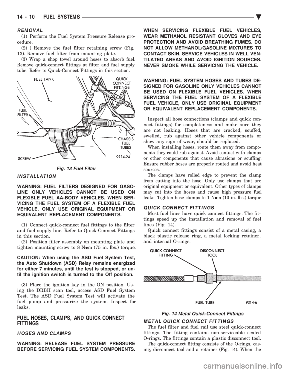
cedure. (2) ) Remove the fuel filter retaining screw (Fig.
13). Remove fuel filter from mounting plate.
(3) Wrap a shop towel around hoses to absorb fuel.
Remove quick-connect fittings at filter and fuel supply
tube. Refer to Quick-Connect Fittings in this section.
INSTALLATION
WARNING: FUEL FILTERS DESIGNED FOR GASO-
LINE ONLY VEHICLES CANNOT BE USED ON
FLEXIBLE FUEL AA-BODY VEHICLES. WHEN SER-
VICING THE FUEL SYSTEM OF A FLEXIBLE FUEL
VEHICLE, ONLY USE ORIGINAL EQUIPMENT OR
EQUIVALENT REPLACEMENT COMPONENTS.
(1) Connect quick-connect fuel fittings to the filter
and fuel supply line. Refer to Quick-Connect Fittings
in this section. (2) Position filter assembly on mounting plate and
tighten mounting screw to 8 N Im (75 in. lbs.) torque.
CAUTION: When using the ASD Fuel System Test,
the Auto Shutdown (ASD) Relay remains energized
for either 7 minutes, until the test is stopped, or un-
til the ignition switch is turned to the Off position.
(3) Place the ignition key in the ON position. Us-
ing the DRBII scan tool, access ASD Fuel System
Test. The ASD Fuel System Test will activate the
fuel pump and pressurize the system. Inspect for
leaks.
FUEL HOSES, CLAMPS, AND QUICK CONNECT
FITTINGS
HOSES AND CLAMPS
WARNING: RELEASE FUEL SYSTEM PRESSURE
BEFORE SERVICING FUEL SYSTEM COMPONENTS. WHEN SERVICING FLEXIBLE FUEL VEHICLES,
WEAR METHANOL RESISTANT GLOVES AND EYE
PROTECTION AND AVOID BREATHING FUMES. DO
NOT ALLOW METHANOL/GASOLINE MIXTURES TO
CONTACT SKIN. SERVICE VEHICLES IN WELL VEN-
TILATED AREAS AND AVOID IGNITION SOURCES.
NEVER SMOKE WHILE SERVICING THE VEHICLE.
WARNING: FUEL SYSTEM HOSES AND TUBES DE-
SIGNED FOR GASOLINE ONLY VEHICLES CANNOT
BE USED ON FLEXIBLE FUEL VEHICLES. WHEN
SERVICING THE FUEL SYSTEM OF A FLEXIBLE
FUEL VEHICLE, ONLY USE ORIGINAL EQUIPMENT
OR EQUIVALENT REPLACEMENT COMPONENTS.
Inspect all hose connections (clamps and quick con-
nect fittings) for completeness and make sure they
are not leaking. Hoses that are cracked, scuffed,
swelled, rub against other vehicle components or
show any sign of wear, should be replaced.
When installing hoses, route them away from compo-
nents they could rub against. Avoid contact with clamps
or other components that cause abrasions or scuffing.
Ensure rubber hoses are properly routed and avoid heat
sources. The clamps have rolled edge to prevent the clamp
from cutting into the hose. Only use clamps that are
original equipment or equivalent. Other types of clamps
may cut into the hoses and cause high pressure fuel
leaks. Tighten hose clamps to 1 N Im (10 in. lbs.) torque.
QUICK CONNECT FITTINGS
Most fuel lines have quick connect fittings. The fit-
tings speed up the installation and removal of fuel
lines (Fig. 14). Quick connect fittings consist of a metal casing, a
black plastic release ring, a metal locking retainer,
and internal O-rings.
METAL QUICK CONNECT FITTINGS
The fuel filter and fuel rail use steel quick-connect
fittings. The fitting contains non-serviceable sealed
O-rings. The fittings contain a plastic disconnect tool.
The quick-connect fitting consists of the O-rings, cas-
ing, disconnect tool and a retainer (Fig. 14). When the
Fig. 13 Fuel Filter
Fig. 14 Metal Quick-Connect Fittings
14 - 10 FUEL SYSTEMS Ä
Page 1751 of 2438
fuel tube enters the fitting, the retainer locks the shoul-
der of the nipple in place and the O-rings seal the tube.
CAUTION: Quick-connect fittings are not serviced
separately. Do not attempt to repair damaged quick-
connect fittings or fuel tubes. Replace the complete
fuel tube/quick-connect fitting assembly.
When installing fuel tubes, route them in the holders
along the frame rail, fuel tank and the rear of the en-
gine.
REMOVAL
WARNING: RELEASE FUEL SYSTEM PRESSURE
BEFORE SERVICING FUEL SYSTEM COMPONENTS.
WHEN SERVICING FLEXIBLE FUEL VEHICLES,
WEAR METHANOL RESISTANT GLOVES AND EYE
PROTECTION AND AVOID BREATHING FUMES. DO
NOT ALLOW METHANOL/GASOLINE MIXTURES TO
CONTACT SKIN. SERVICE VEHICLES IN WELL VEN-
TILATED AREAS AND AVOID IGNITION SOURCES.
NEVER SMOKE WHILE SERVICING THE VEHICLE.
(1) Disconnect negative cable from the battery.
(2) Perform the Fuel Pressure Release Procedure.
Refer to the Fuel Pressure Release Procedure in this
section. (3) Remove any loose dirt from quick connect fit-
tings.
WARNING: WRAP SHOP TOWELS AROUND HOSES
TO CATCH ANY FUEL SPILLAGE.
(4) Push the quick connect fitting toward the fuel
tube while depressing the built-in release tool. Then
slightly twist the fitting and pull it off the fuel tube
(Fig. 14). (5) Cover the fitting to prevent contamination.
TUBE/FITTING SERVICE
WARNING: RELEASE FUEL SYSTEM PRESSURE
BEFORE SERVICING FUEL SYSTEM COMPONENTS.
WHEN SERVICING FLEXIBLE FUEL VEHICLES,
WEAR METHANOL RESISTANT GLOVES AND EYE
PROTECTION AND AVOID BREATHING FUMES. DO
NOT ALLOW METHANOL/GASOLINE MIXTURES TO
CONTACT SKIN. SERVICE VEHICLES IN WELL VEN-
TILATED AREAS AND AVOID IGNITION SOURCES.
NEVER SMOKE WHILE SERVICING THE VEHICLE.
If a quick connect fitting needs service, the follow-
ing procedure must be followed: (1) Disconnect the battery negative battery cable.
(2) Perform the Fuel System Pressure Release Pro-
cedure.
WARNING: WRAP SHOP TOWELS AROUND HOSES
TO CATCH ANY FUEL SPILLAGE. (3) Remove the quick connect fitting from the fuel
tube by pushing in on the plastic ring located on the
end of the fitting. Gently pull the fitting from the
fuel tube. (4) Cut off the crimp ferrules at each end of the
hose, taking care not to damage the quick connect
fitting or the fuel tube. (5) Discard the ferrules and hose.
WARNING: FUEL SYSTEM HOSES AND TUBES DE-
SIGNED FOR GASOLINE ONLY VEHICLES CANNOT
BE USED ON FLEXIBLE FUEL VEHICLES. WHEN
SERVICING THE FUEL SYSTEM OF A FLEXIBLE
FUEL VEHICLE, ONLY USE ORIGINAL EQUIPMENT
OR EQUIVALENT REPLACEMENT COMPONENTS.
(6) Replace the hose using original equipment or
equivalent hose. (7) Attach the replacement hose to the quick con-
nect fitting and fuel tube using the correct hose
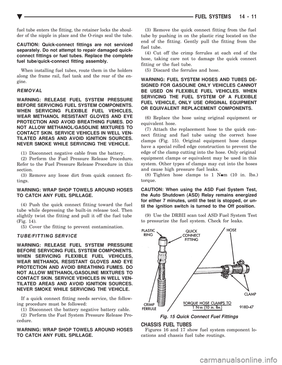
clamps (Fig. 15). Original equipment hose clamps
have a special rolled edge construction to prevent the
edge of the clamp cutting into the hose. Only original
equipment clamps or equivalent may be used in this
system. Other types of clamps may cut into the hoses
and cause high pressure fuel leaks. (8) Tighten hose clamps to 1 N Im (10 in. lbs.)
torque.
CAUTION: When using the ASD Fuel System Test,
the Auto Shutdown (ASD) Relay remains energized
for either 7 minutes, until the test is stopped, or un-
til the ignition switch is turned to the Off position.
(9) Use the DRBII scan tool ASD Fuel System Test
to pressurize the fuel system. Check for leaks.
CHASSIS FUEL TUBES
Figures 16 and 17 show fuel system component lo-
cations and chassis fuel tube routings.
Fig. 15 Quick Connect Fuel Fittings
Ä FUEL SYSTEMS 14 - 11
Page 1788 of 2438
2.2L/2.5L SINGLE POINT FUEL INJECTIONÐSERVICE PROCEDURES INDEX
page page
Canister Purge Solenoid ................... 53
Electric Exhaust Gas Recirculation Transducer (EET) Service ............................... 53
Fuel Fitting ............................. 50
Fuel Injector ............................ 51
Fuel Lines and Hoses ..................... 48
Fuel Pressure Regulator ................... 51 Fuel System Pressure Release Procedure
...... 48
Heated Oxygen Sensor (O
2Sensor) .......... 54
Idle Air Control Motor ..................... 53
Manifold Absolute Pressure Sensor ........... 53
PCM Service ............................ 54
Throttle Body ............................ 48
Throttle Position Sensor ................... 52
FUEL LINES AND HOSES
Perform the Fuel System Pressure Relief Procedure
before servicing the fuel system. The procedure must
be done to bleed fuel pressure from the system before
removing clamps or hoses. Use care when removing fuel hoses to prevent dam-
age to hose or hose nipple. Always use new hose
clamps, of the correct type, during reassembly. Tighten
hose clamps to 1 N Im (10 in. lbs.) torque. Do not use
aviation style clamps on this system or hose
damage may result.
FUEL SYSTEM PRESSURE RELEASE PROCEDURE
CAUTION: Before servicing the fuel pump, fuel lines,
fuel filter, throttle body, or fuel injector, release fuel
system pressure.
(1) Loosen fuel filler cap to release fuel tank pres-
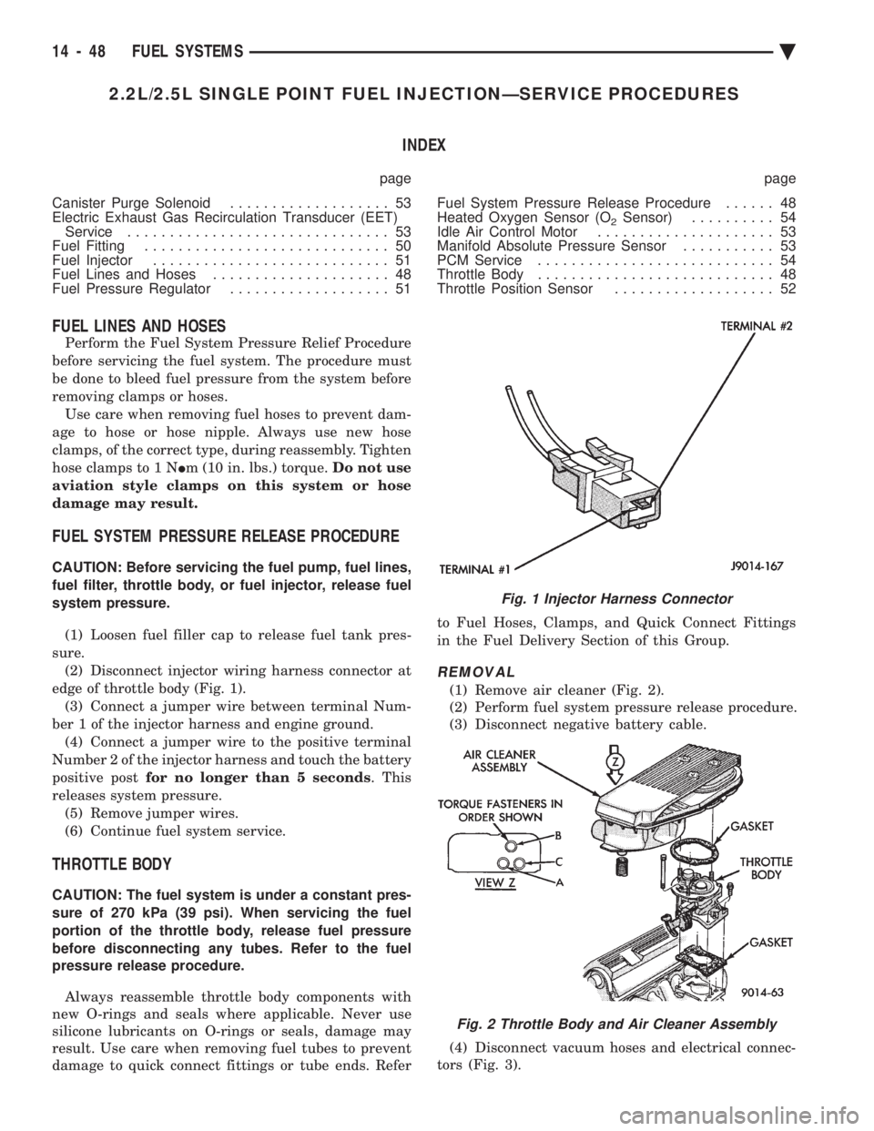
sure. (2) Disconnect injector wiring harness connector at
edge of throttle body (Fig. 1). (3) Connect a jumper wire between terminal Num-
ber 1 of the injector harness and engine ground. (4) Connect a jumper wire to the positive terminal
Number 2 of the injector harness and touch the battery
positive post for no longer than 5 seconds . This
releases system pressure. (5) Remove jumper wires.
(6) Continue fuel system service.
THROTTLE BODY
CAUTION: The fuel system is under a constant pres-
sure of 270 kPa (39 psi). When servicing the fuel
portion of the throttle body, release fuel pressure
before disconnecting any tubes. Refer to the fuel
pressure release procedure.
Always reassemble throttle body components with
new O-rings and seals where applicable. Never use
silicone lubricants on O-rings or seals, damage may
result. Use care when removing fuel tubes to prevent
damage to quick connect fittings or tube ends. Refer to Fuel Hoses, Clamps, and Quick Connect Fittings
in the Fuel Delivery Section of this Group.
REMOVAL
(1) Remove air cleaner (Fig. 2).
(2) Perform fuel system pressure release procedure.
(3) Disconnect negative battery cable.
(4) Disconnect vacuum hoses and electrical connec-
tors (Fig. 3).
Fig. 1 Injector Harness Connector
Fig. 2 Throttle Body and Air Cleaner Assembly
14 - 48 FUEL SYSTEMS Ä