1993 CHEVROLET PLYMOUTH ACCLAIM ignition
[x] Cancel search: ignitionPage 1600 of 2438
CAMSHAFT AND CRANKSHAFT TIMING
PROCEDURE
INSTALLATION
(1) Remove air cleaner fresh air duct.
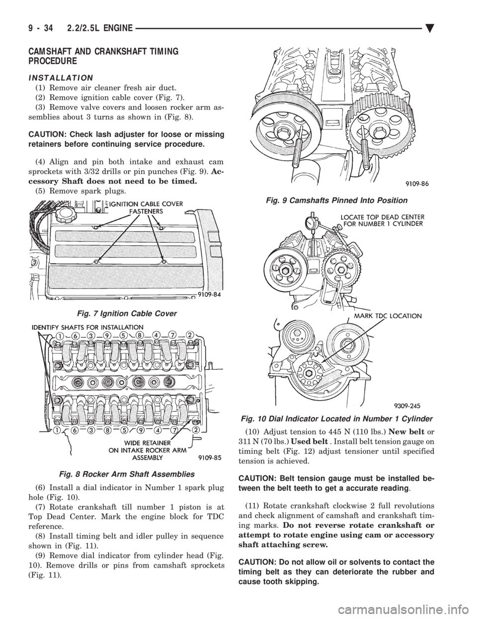
(2) Remove ignition cable cover (Fig. 7).
(3) Remove valve covers and loosen rocker arm as-
semblies about 3 turns as shown in (Fig. 8).
CAUTION: Check lash adjuster for loose or missing
retainers before continuing service procedure.
(4) Align and pin both intake and exhaust cam
sprockets with 3/32 drills or pin punches (Fig. 9). Ac-
cessory Shaft does not need to be timed. (5) Remove spark plugs.
(6) Install a dial indicator in Number 1 spark plug
hole (Fig. 10). (7) Rotate crankshaft till number 1 piston is at
Top Dead Center. Mark the engine block for TDC
reference. (8) Install timing belt and idler pulley in sequence
shown in (Fig. 11). (9) Remove dial indicator from cylinder head (Fig.
10). Remove drills or pins from camshaft sprockets
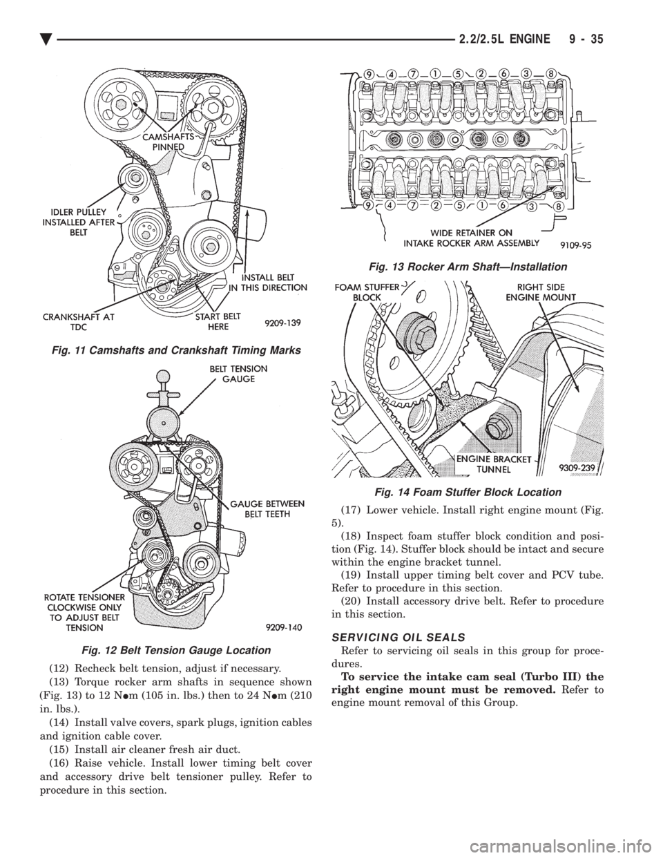
(Fig. 11). (10) Adjust tension to 445 N (110 lbs.)
New beltor
311 N (70 lbs.) Used belt. Install belt tension gauge on
timing belt (Fig. 12) adjust tensioner until specified
tension is achieved.
CAUTION: Belt tension gauge must be installed be-
tween the belt teeth to get a accurate reading .
(11) Rotate crankshaft clockwise 2 full revolutions
and check alignment of camshaft and crankshaft tim-
ing marks. Do not reverse rotate crankshaft or
attempt to rotate engine using cam or accessory
shaft attaching screw.
CAUTION: Do not allow oil or solvents to contact the
timing belt as they can deteriorate the rubber and
cause tooth skipping.
Fig. 7 Ignition Cable Cover
Fig. 8 Rocker Arm Shaft Assemblies
Fig. 9 Camshafts Pinned Into Position
Fig. 10 Dial Indicator Located in Number 1 Cylinder
9 - 34 2.2/2.5L ENGINE Ä
Page 1601 of 2438
(12) Recheck belt tension, adjust if necessary.
(13) Torque rocker arm shafts in sequence shown
(Fig. 13) to 12 N Im (105 in. lbs.) then to 24 N Im (210
in. lbs.). (14) Install valve covers, spark plugs, ignition cables
and ignition cable cover. (15) Install air cleaner fresh air duct.
(16) Raise vehicle. Install lower timing belt cover
and accessory drive belt tensioner pulley. Refer to
procedure in this section. (17) Lower vehicle. Install right engine mount (Fig.
5). (18) Inspect foam stuffer block condition and posi-
tion (Fig. 14). Stuffer block should be intact and secure
within the engine bracket tunnel. (19) Install upper timing belt cover and PCV tube.
Refer to procedure in this section. (20) Install accessory drive belt. Refer to procedure
in this section.
SERVICING OIL SEALS
Refer to servicing oil seals in this group for proce-
dures. To service the intake cam seal (Turbo III) the
right engine mount must be removed. Refer to
engine mount removal of this Group.
Fig. 13 Rocker Arm ShaftÐInstallation
Fig. 14 Foam Stuffer Block Location
Fig. 11 Camshafts and Crankshaft Timing Marks
Fig. 12 Belt Tension Gauge Location
Ä 2.2/2.5L ENGINE 9 - 35
Page 1673 of 2438
length of the spring to be tested is 33.34mm (1-5/16
inches). Turn table of Tool C-647 until surface is in line
with the 33.34mm (1-5/16 inch) mark on the threaded
stud and the zero mark on the front. Place spring over
stud on the table and lift compressing lever to set tone
device. Pull on torque wrench until ping is heard. Take
reading on torque wrench at this instant. Multiply this
reading by two. This will give the spring load at test
length. Fractional measurements are indicated on the
table for finer adjustments. Refer to specifications to
obtain specified height and allowable tensions. Discard
the springs that do not meet specifications.
VALVE INSTALLATION
(1) Coat valve stems with clean engine oil and insert
them in cylinder head. (2) Check valve tip to spring seat dimension A after
grinding the valve seats or faces. Grind valve tip to give
49.541 to 51.271 mm (1.950 to 2.018 inch.) over spring
seat when installed in the head (Fig. 17). Check valve
tip for scoring, if necessary, the tip chamfer should be
reground to prevent seal damage when the valve is
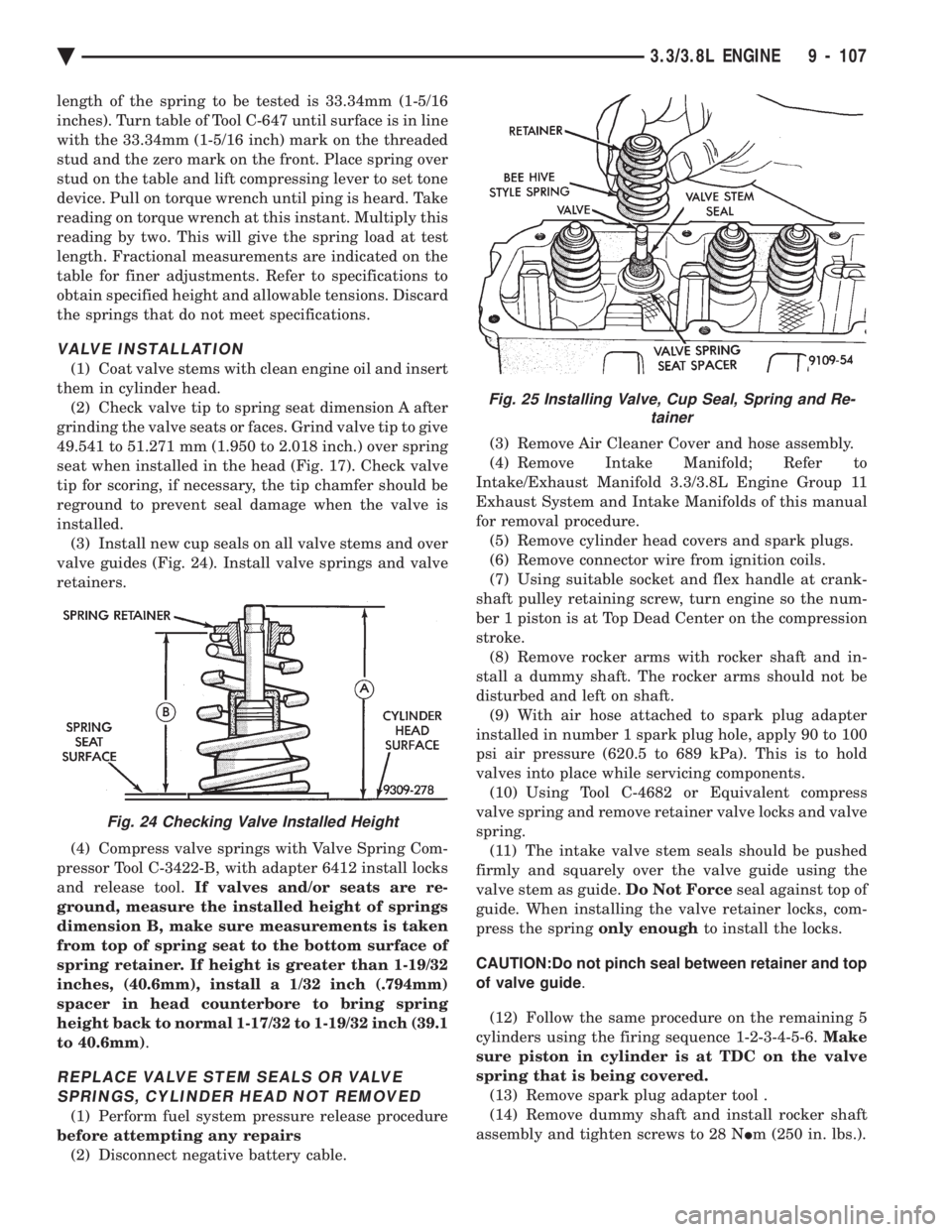
installed. (3) Install new cup seals on all valve stems and over
valve guides (Fig. 24). Install valve springs and valve
retainers.
(4) Compress valve springs with Valve Spring Com-
pressor Tool C-3422-B, with adapter 6412 install locks
and release tool. If valves and/or seats are re-
ground, measure the installed height of springs
dimension B, make sure measurements is taken
from top of spring seat to the bottom surface of
spring retainer. If height is greater than 1-19/32
inches, (40.6mm), install a 1/32 inch (.794mm)
spacer in head counterbore to bring spring
height back to normal 1-17/32 to 1-19/32 inch (39.1
to 40.6mm) .
REPLACE VALVE STEM SEALS OR VALVE
SPRINGS, CYLINDER HEAD NOT REMOVED
(1) Perform fuel system pressure release procedure
before attempting any repairs (2) Disconnect negative battery cable. (3) Remove Air Cleaner Cover and hose assembly.
(4) Remove Intake Manifold; Refer to
Intake/Exhaust Manifold 3.3/3.8L Engine Group 11
Exhaust System and Intake Manifolds of this manual
for removal procedure. (5) Remove cylinder head covers and spark plugs.
(6) Remove connector wire from ignition coils.
(7) Using suitable socket and flex handle at crank-
shaft pulley retaining screw, turn engine so the num-
ber 1 piston is at Top Dead Center on the compression
stroke. (8) Remove rocker arms with rocker shaft and in-
stall a dummy shaft. The rocker arms should not be
disturbed and left on shaft. (9) With air hose attached to spark plug adapter
installed in number 1 spark plug hole, apply 90 to 100
psi air pressure (620.5 to 689 kPa). This is to hold
valves into place while servicing components. (10) Using Tool C-4682 or Equivalent compress
valve spring and remove retainer valve locks and valve
spring. (11) The intake valve stem seals should be pushed
firmly and squarely over the valve guide using the
valve stem as guide. Do Not Forceseal against top of
guide. When installing the valve retainer locks, com-
press the spring only enoughto install the locks.
CAUTION:Do not pinch seal between retainer and top
of valve guide .
(12) Follow the same procedure on the remaining 5
cylinders using the firing sequence 1-2-3-4-5-6. Make
sure piston in cylinder is at TDC on the valve
spring that is being covered. (13) Remove spark plug adapter tool .
(14) Remove dummy shaft and install rocker shaft
assembly and tighten screws to 28 N Im (250 in. lbs.).
Fig. 24 Checking Valve Installed Height
Fig. 25 Installing Valve, Cup Seal, Spring and Re-
tainer
Ä 3.3/3.8L ENGINE 9 - 107
Page 1674 of 2438
(15) Install rocker arm covers tighten screws to 14
N Im (120 in. lbs.) and connector to ignition coils.
(16) Install Intake Manifold; Refer to Intake Mani-
fold Installation 3.3/3.8L Engine, Group 11 Exhaust
System and Intake Manifold.
HYDRAULIC TAPPETS
The valve train includes roller tappet assemblies,
aligning yokes and yoke retainer. Roller tappet alignment is maintained by machined
flats on tappet body being fitted in pairs into six
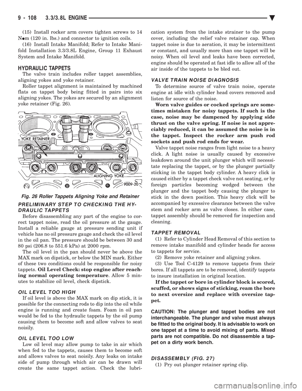
aligning yokes. The yokes are secured by an alignment
yoke retainer (Fig. 26).
PRELIMINARY STEP TO CHECKING THE HY- DRAULIC TAPPETS
Before disassembling any part of the engine to cor-
rect tappet noise, read the oil pressure at the gauge.
Install a reliable gauge at pressure sending unit if
vehicle has no oil pressure gauge and check the oil level
in the oil pan. The pressure should be between 30 and
80 psi (206.8 to 551.6 kPa) at 2000 rpm. The oil level in the pan should never be above the
MAX mark on dipstick, or below the MIN mark. Either
of these two conditions could be responsible for noisy
tappets. Oil Level Check: stop engine after reach-
ing normal operating temperature . Allow 5 min-
utes to stabilize oil level, check dipstick.
OIL LEVEL TOO HIGH
If oil level is above the MAX mark on dip stick, it is
possible for the connecting rods to dip into the oil while
engine is running and create foam. Foam in oil pan
would be fed to the hydraulic tappets by the oil pump
causing them to become soft and allow valves to seat
noisily.
OIL LEVEL TOO LOW
Low oil level may allow pump to take in air which
when fed to the tappets, causes them to become soft
and allows valves to seat noisily. Any leaks on intake
side of pump through which air can be drawn will
create the same tappet action. Check the lubri- cation system from the intake strainer to the pump
cover, including the relief valve retainer cap. When
tappet noise is due to aeration, it may be intermittent
or constant, and usually more than one tappet will be
noisy. When oil level and leaks have been corrected,
engine should be operated at fast idle to allow all of the
air inside of the tappets to be bled out.
VALVE TRAIN NOISE DIAGNOSIS
To determine source of valve train noise, operate
engine at idle with cylinder head covers removed and
listen for source of the noise. Worn valve guides or cocked springs are some-
times mistaken for noisy tappets. If such is the
case, noise may be dampened by applying side
thrust on the valve spring. If noise is not appre-
ciably reduced, it can be assumed the noise is in
the tappet. Inspect the rocker arm push rod
sockets and push rod ends for wear. Valve tappet noise ranges from light noise to a heavy
click. A light noise is usually caused by excessive
leakdown around the unit plunger which will necessi-
tate replacing the tappet, or by the plunger partially
sticking in the tappet body cylinder. A heavy click is
caused either by a tappet check valve not seating, or by
foreign particles becoming wedged between the
plunger and the tappet body causing the plunger to
stick in the down position. This heavy click will be
accompanied by excessive clearance between the valve
stem and rocker arm as valve closes. In either case,
tappet assembly should be removed for inspection and
cleaning.
TAPPET REMOVAL
(1) Refer to Cylinder Head Removal of this section to
remove intake manifold and cylinder heads for access
to tappets for service. (2) Remove yoke retainer and aligning yokes.
(3) Use Tool C-4129 to remove tappets from their
bores. If all tappets are to be removed, identify tappets
to insure installation in original location. If the tappet or bore in cylinder block is scored,
scuffed, or shows signs of sticking, ream the bore
to next oversize and replace with oversize tap-
pet.
CAUTION: The plunger and tappet bodies are not
interchangeable. The plunger and valve must always
be fitted to the original body. It is advisable to work on
one tappet at a time to avoid mixing of parts. Mixed
parts are not compatible. Do not disassemble a tap-
pet on a dirty work bench.
DISASSEMBLY (FIG. 27)
(1) Pry out plunger retainer spring clip.
Fig. 26 Roller Tappets Aligning Yoke and Retainer
9 - 108 3.3/3.8L ENGINE Ä
Page 1677 of 2438
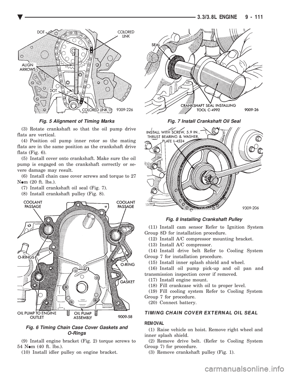
(3) Rotate crankshaft so that the oil pump drive
flats are vertical. (4) Position oil pump inner rotor so the mating
flats are in the same position as the crankshaft drive
flats (Fig. 6). (5) Install cover onto crankshaft. Make sure the oil
pump is engaged on the crankshaft correctly or se-
vere damage may result. (6) Install chain case cover screws and torque to 27
N Im (20 ft. lbs.).
(7) Install crankshaft oil seal (Fig. 7).
(8) Install crankshaft pulley (Fig. 8).
(9) Install engine bracket (Fig. 2) torque screws to
54 N Im (40 ft. lbs.).
(10) Install idler pulley on engine bracket. (11) Install cam sensor Refer to Ignition System
Group 8D for installation procedure. (12) Install A/C compressor mounting bracket.
(13) Install A/C compressor.
(14) Install drive belt Refer to Cooling System
Group 7 for installation procedure. (15) Install inner splash shield and wheel.
(16) Install oil pump pick-up and oil pan and
transmission inspection cover if removed. (17) Install engine mount.
(18) Fill crankcase with oil to proper level.
(19) Fill cooling system Refer to Cooling System
Group 7 for procedure. (20) Connect battery.
TIMING CHAIN COVER EXTERNAL OIL SEAL
REMOVAL
(1) Raise vehicle on hoist. Remove right wheel and
inner splash shield. (2) Remove drive belt. (Refer to Cooling System
Group 7) for procedure. (3) Remove crankshaft pulley (Fig. 1).
Fig. 5 Alignment of Timing Marks
Fig. 6 Timing Chain Case Cover Gaskets and O-Rings
Fig. 7 Install Crankshaft Oil Seal
Fig. 8 Installing Crankshaft Pulley
Ä 3.3/3.8L ENGINE 9 - 111
Page 1703 of 2438
CLEANING AND INSPECTION
(1) Discard gaskets and clean all gasket surfaces
on both manifolds and on cylinder head. (2) Test gasket surfaces of manifolds for flatness
with a straight edge. Surfaces must be flat within
0.15mm per 300mm (.006 in. per foot) of manifold
length. (3) Inspect manifolds for cracks and distortion.
INSTALLATION
(1) Install a new intake and exhaust manifold gas-
ket. Coat steel gasket lightly with Gasket Sealer on
manifold side. Do notcoat composition gasket with
(any) sealer. (2) Set exhaust manifold in place. Tighten retain-
ing nuts starting at center and progressing outward
in both directions to 23 N Im (200 in. lbs.) torque. Re-
peat this procedure until all nuts are at specified
torque. (3) Set intake manifold in place.
(4) Raise vehicle and tighten retaining screws
starting at center and progressing outward in both
directions to 23 N Im (200 in. lbs.) torque (Fig. 3). Re-
peat this procedure until all screws are at specified
torque. (5) Reverse removal procedures 1-9 for installation.
(6) With the DRBII Scan Tool use ASD Fuel Sys-
tem Test to pressurize system to check for leaks.
CAUTION: When using the ASD Fuel System Test,
the Auto Shutdown (ASD) relay will remain ener-
gized for 7 minutes or until the ignition switch is
turned to the OFF position, or Stop All Test is se-
lected.
INTAKE AND EXHAUST MANIFOLDSÐFLEXIBLE
FUEL ENGINE
INTAKE MANIFOLD
The manifold is die-cast aluminum with upper ple-
num and 4 tubes lower runners. These attach to the
cylinder head, with each runner leading directly to a
cylinder. The manifold is also machined for fuel rail attach-
ment and injector installation. The throttle body is
installed on the upper plenum of the manifold.
EXHAUST MANIFOLD
All high strength iron casting that intermesh with
the intake manifold. For standard engines a four
branch design collects and directs exhaust gases to
the conical (articulated joint connection) outlet.
INTAKE/EXHAUST MANIFOLDS
SERVICEÐFLEXIBLE FUEL ENGINES
Intake and exhaust manifolds use a one piece gas-
ket. Service procedures requiring removal and instal-
lation of either must include both manifolds.
SERVICE PRECAUTIONS
Methanol is more toxic than gasoline. Always re-
lease fuel system pressure before servicing fuel sys-
tem components and wear methanol resistant gloves
and eye protection. Avoid breathing methanol vapors or ingesting
methanol. Headaches, dizziness and even uncon-
sciousness could result from breathing these vapors.
Serious injury, blindness and even death could result
from ingesting methanol. Methanol vapors are extremely flammable and can
travel along the ground. Service vehicles in well ven-
tilated areas and avoid ignition sources. Never
smoke while servicing the vehicle. Do not allow methanol to contact skin. Prolonged
contact with methanol can cause dry skin or an al-
lergic skin reaction. Also, prolonged contact could re-
sult in absorption through the skin.
FUEL SYSTEM PRESSURE RELEASE PROCEDURE
WARNING: RELEASE FUEL SYSTEM PRESSURE
BEFORE SERVICING FUEL SYSTEM COMPONENTS.
WEAR METHANOL RESISTANT GLOVES AND EYE
PROTECTION WHILE SERVICING THE FUEL SYS-
TEM.
(a) Disconnect negative cable from battery.
(b) Remove fuel filler cap.
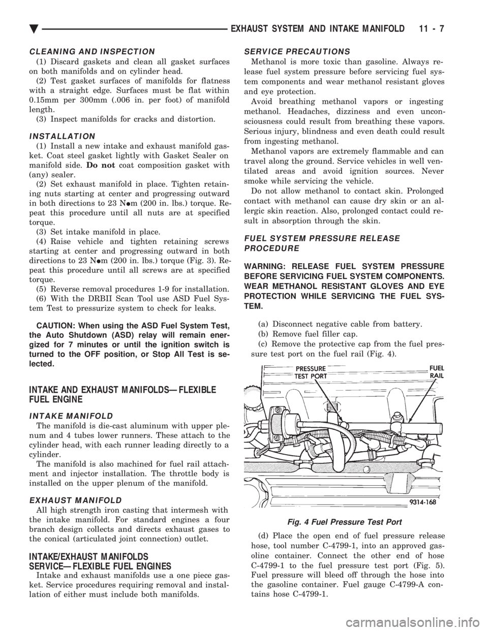
(c) Remove the protective cap from the fuel pres-
sure test port on the fuel rail (Fig. 4).
(d) Place the open end of fuel pressure release
hose, tool number C-4799-1, into an approved gas-
oline container. Connect the other end of hose
C-4799-1 to the fuel pressure test port (Fig. 5).
Fuel pressure will bleed off through the hose into
the gasoline container. Fuel gauge C-4799-A con-
tains hose C-4799-1.
Fig. 4 Fuel Pressure Test Port
Ä EXHAUST SYSTEM AND INTAKE MANIFOLD 11 - 7
Page 1705 of 2438
EXHAUST MANIFOLD
REMOVAL (1) Disconnect exhaust pipe from manifold articu-
late joint. (2) Disconnect the heated oxygen sensor electrical
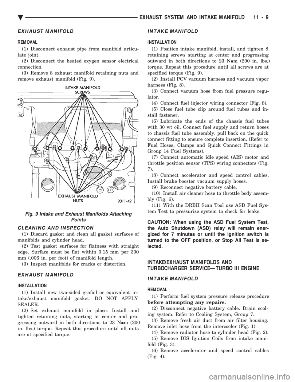
connection. (3) Remove 8 exhaust manifold retaining nuts and
remove exhaust manifold (Fig. 9).
CLEANING AND INSPECTION
(1) Discard gasket and clean all gasket surfaces of
manifolds and cylinder head. (2) Test gasket surfaces for flatness with straight
edge. Surface must be flat within 0.15 mm per 300
mm (.006 in. per foot) of manifold length. (3) Inspect manifolds for cracks or distortion.
EXHAUST MANIFOLD
INSTALLATION
(1) Install new two-sided grafoil or equivalent in-
take/exhaust manifold gasket. DO NOT APPLY
SEALER. (2) Set exhaust manifold in place. Install and
tighten retaining nuts, starting at center and pro-
gressing outward in both directions to 23 N Im (200
in. lbs.) torque. Repeat this procedure until all nuts
are at specified torque.
INTAKE MANIFOLD
INSTALLATION
(1) Position intake manifold, install, and tighten 8
retaining screws starting at center and progressing
outward in both directions to 23 N Im (200 in. lbs.)
torque. Repeat this procedure until all screws are at
specified torque (Fig. 9). (2) Install PCV vacuum harness and vacuum vapor
harness (Fig. 8). (3) Connect vacuum hose from fuel pressure regu-
lator. (4) Connect fuel injector wiring connector (Fig. 8).
(5) Close fuel tube clip around fuel tubes and in-
stall fastener. (6) Lubricate the ends of the chassis fuel tubes
with 30 wt oil. Connect fuel supply and return hoses
to chassis fuel tube assembly. pull back on the quick
connect fitting to ensure complete insertion. (Refer to
Fuel Hoses, Clamps and Quick Connect Fittings in
Group 14 Fuel Systems). (7) Connect automatic idle speed (AIS) motor and
throttle position sensor (TPS) wiring connectors (Fig.
7). (8) Connect accelerator and speed control cables.
Install brake booster vacuum supply hoses. (9) Reconnect negative battery cable.
(10) Install air cleaner hose to throttle body assem-
bly (Fig. 6). (11) With the DRBII Scan Tool use ASD Fuel Sys-
tem Test to pressurize system to check for leaks.
CAUTION: When using the ASD Fuel System Test,
the Auto Shutdown (ASD) relay will remain ener-
gized for 7 minutes or until the ignition switch is
turned to the OFF position, or Stop All Test is se-
lected.
INTAKE/EXHAUST MANIFOLDS AND
TURBOCHARGER SERVICEÐTURBO III ENGINE
INTAKE MANIFOLD
REMOVAL
(1) Perform fuel system pressure release procedure
before attempting any repairs. (2) Disconnect negative battery cable. Drain cool-
ing system. Refer to Cooling System, Group 7. (3) Remove fresh air duct from air filter housing.
Remove inlet hose from the intercooler (Fig. 1). (4) Remove radiator hose to cylinder head (Fig. 2).
(5) Remove DIS Ignition Coils from intake mani-
fold (Fig. 3). (6) Remove accelerator and speed control cables
(Fig. 4).
Fig. 9 Intake and Exhaust Manifolds Attaching Points
Ä EXHAUST SYSTEM AND INTAKE MANIFOLD 11 - 9
Page 1706 of 2438
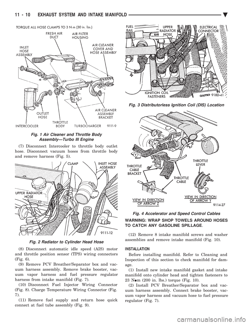
(7) Disconnect Intercooler to throttle body outlet
hose. Disconnect vacuum hoses from throttle body
and remove harness (Fig. 5).
(8) Disconnect automatic idle speed (AIS) motor
and throttle position sensor (TPS) wiring connectors
(Fig. 6). (9) Remove PCV Breather/Separator box and vac-
uum harness assembly. Remove brake booster, vac-
uum vapor harness and fuel pressure regulator
harness from intake manifold (Fig. 7). (10) Disconnect Fuel Injector Wiring Connector
(Fig. 8). Charge Temperature Wiring Connector (Fig.
7). (11) Remove fuel supply and return hose quick
connect at fuel tube assembly (Fig. 9). WARNING: WRAP SHOP TOWELS AROUND HOSES
TO CATCH ANY GASOLINE SPILLAGE
.
(12) Remove 8 intake manifold screws and washer
assemblies and remove intake manifold (Fig. 10).
INSTALLATION
Before installing manifold. Refer to Cleaning and
Inspection of this section to check manifold for dam-
age. (1) Install new intake manifold gasket and intake
manifold onto cylinder head and tighten fasteners to
23 N Im (200 in. lbs.) torque (Fig. 10).
(2) Install PCV Breather/Separator box and vac-
uum harness assembly. Connect brake booster, vac-
uum vapor harness and vacuum hose to fuel pressure
regulator (Fig. 7).
Fig. 1 Air Cleaner and Throttle Body AssemblyÐTurbo III Engine
Fig. 2 Radiator to Cylinder Head Hose
Fig. 3 Distributorless Ignition Coil (DIS) Location
Fig. 4 Accelerator and Speed Control Cables
11 - 10 EXHAUST SYSTEM AND INTAKE MANIFOLD Ä