1993 CHEVROLET PLYMOUTH ACCLAIM ignition
[x] Cancel search: ignitionPage 567 of 2438

AUDIO SYSTEM
CONTENTS
page page
ANTENNAS ............................ 20
COMPACT DISC PLAYER ................. 30 RADIOS
................................ 1
SPEAKERS ............................ 24
RADIOS INDEX
page page
Audio Diagnostic Test Procedures ............. 1
Description .............................. 1
Interference Elimination ..................... 1
Radio Removal AP Body Replacement ........ 19 Radio RemovalÐAA Body
.................. 18
Radio RemovalÐAC and AY Bodies .......... 18
Radio RemovalÐAG and AJ Bodies .......... 18
DESCRIPTION
For operation of the factory installed standard and
optional radios and the optional compact disc player,
refer to the Sound Systems Operating Instructions
Manual supplied with the vehicle. All vehicles are equipped with an Ignition-Off
Draw Connector which, is used when the vehicles are
originally shipped from the factory. This connector
which, is located near the battery, helps to prevent
battery discharge during storage. For specific connec-
tor type and location, refer to Group 8W, Wiring Di-
agrams. This connector is included in the radio memory cir-
cuitry and should be checked if the memory of time
or radio station programming is inoperative.
INTERFERENCE ELIMINATION
Some components are used on vehicles equipped
with a radio capacitor, to suppress radio frequency
interference/static. Capacitors are mounted in various locations, on the
generator either internal or external, internal to the
instrument cluster, and internal to the windshield
wiper motor. Ground straps are mounted from radio chassis to
instrument panel support structure, engine to cowl,
across engine mount on right hand side. On vehicles
with air conditioning there is a strap from evapora-
tor valve to cowl. These ground straps should be se-
curely tightened to assure good metal to metal
contact. Ground straps conduct very small high fre-
quency electrical signals to ground and require clean
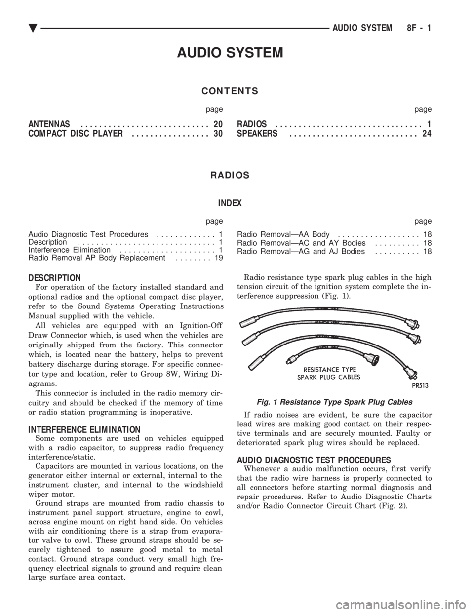
large surface area contact. Radio resistance type spark plug cables in the high
tension circuit of the ignition system complete the in-
terference suppression (Fig. 1).
If radio noises are evident, be sure the capacitor
lead wires are making good contact on their respec-
tive terminals and are securely mounted. Faulty or
deteriorated spark plug wires should be replaced.
AUDIO DIAGNOSTIC TEST PROCEDURES
Whenever a audio malfunction occurs, first verify
that the radio wire harness is properly connected to
all connectors before starting normal diagnosis and
repair procedures. Refer to Audio Diagnostic Charts
and/or Radio Connector Circuit Chart (Fig. 2).
Fig. 1 Resistance Type Spark Plug Cables
Ä AUDIO SYSTEM 8F - 1
Page 587 of 2438

INSTALLATION
(1) Install antenna body and cable from under-
neath fender (Fig. 12). (2) Install gasket, adapter, and cap nut. Tighten
cap nut to 14 N Im (125 in. lbs.) with Antenna Nut
Wrench C-4816. (3) Install antenna mast into antenna body until
sleeve bottoms on antenna body (Fig. 11). (4) Route cable to radio if necessary.
BENCH TEST FOR ANTENNA MALFUNCTION
It is also possible to check short or open circuits
with an ohmmeter or continuity light once the an-
tenna has been removed from the vehicle. (1) Continuity should be present between the tip of
the mast and radio end pin (Fig. 13 and 14).
(2) No continuity should be observed or a very high
resistance of several megohms between the ground
shell of the connector and radio end pin.
(3) Continuity should be observed between the ground
shell of the connector and the mounting hardware.
Wiggle cable over its entire length to reveal inter-
mittent short or open circuits during step 1, 2 and 3.
POWER ANTENNA
OPERATION
The power operated radio antenna (Fig. 15) is a
telescoping type antenna, extended and retracted by a
reversible electric motor. The Automatic Power Antenna is controlled by a
combination of an external relay and limit switches
built into the antenna motor housing. The antenna is
actuated when radio is switched ON and the ignition
switch in ON or ACCESSORY position. The antenna
mast should extend. When the ignition switch or radio
is turned OFF the antenna mast should fully retract
and declutch.
Many antenna problems may be avoided by frequent
cleaning of the antenna mast telescoping sections. Clean
the antenna mast sections with a clean soft cloth.
Before an antenna is removed, the antenna perfor-
mance should be tested to decide if it is a reception
problem or an operational problem. Whenever an operational malfunction occurs, first
verify that the radio antenna wire harness is properly
connected. Check all connectors before starting normal
diagnosis and repair procedures. Refer to Power An-
tenna Electrical Diagnosis Chart (Fig. 16).
Fig. 12 Antenna Mounting
Fig. 11 Removing or Tightening Antenna Cap Nut
Fig. 13 Antenna Bench Test Points
Fig. 14 Antenna Bench Test PointsÐTwo Part
Ä AUDIO SYSTEM 8F - 21
Page 589 of 2438

(8) Upon establishing that the fault is in the an-
tenna assembly, it may be traced to one or more of
the following conditions: (a) Broken lead-in wire or shielding.
(b) Grounded lead-in wire or mast assembly.
(c) Moisture in support tube or lead-in assembly.
(d) Poor connection at antenna lead-in assembly
or shielding ground.
REMOVAL
(1) Disconnect battery negative cable.
(2) Remove the right front fender splash shield fas-
teners and pull shield away from the wheel housing.
(3) Disconnect motor leads at the connector (Fig. 15).
(4) Disconnect lead-in cable by twisting at connec-
tor (Fig. 17).
(5) Remove one screw attaching antenna to an-
tenna brace (Fig. 18). (6) Remove cap nut on fender surface with An-
tenna Nut Wench C-4816 (Fig. 11). (7) Remove antenna from under fender.
INSTALLATION
(1) Position antenna under fender and through
fender adapter. (2) Replace and tighten cap nut to 14 N Im (125 in.
lbs.) torque with Antenna Nut Wench C-4816.
(3) Position antenna on antenna brace and install at-
taching screw. Tighten to 4 N Im (40 in. lbs.) torque.
(4) Connect antenna lead at twist connector.
(5) Connect motor leads at connector.
(6) Position right front fender splash shield and in-
stall attaching fasteners. (7) Connect negative battery cable and test opera-
tion of antenna.
POWER ANTENNA MAST
REMOVAL
(1) Remove cap nut using Antenna Nut Wrench
C-4816. (2) Install temporary nut provided with the re-
placement mast. (3) Turn ignition key to ACCESSORY position and
turn on radio. (4) While the mast is moving up pull upward to re-
move mast and drive rod from the mast tube.
INSTALLATION
(1) Insert new drive rod into mast tube with drive
teeth toward antenna motor (Fig. 19).
(2) Turn off radio and guide mast into tube. The
mast may not be fully lowered when first installed. (3) Replace the temporary nut with the original
cap nut and tighten to 14 N Im (125 in. lbs.) torque
using Antenna Nut Wench C-4816. (4) Turn radio on and off to extend and retract an-
tenna. Mast should be fully lowered after recycling.
Fig. 18 Power Antenna Mounting
Fig. 17 Power Antenna Twist Connector
Fig. 19 Power Antenna Mast
Ä AUDIO SYSTEM 8F - 23
Page 603 of 2438

VEHICLE SPEED CONTROL
CONTENTS
page page
CHECKING FOR FAULT CODE .............. 3
DIAGNOSIS PROCEDURES ................ 2
GENERAL INFORMATION .................. 1
INOPERATIVE SYSTEM ................... 3
POWERTRAIN CONTROL MODULE ELECTRICAL TEST ................................ 5
ROAD TEST ............................ 2
SERVO ELECTRICAL TESTS ............... 4
SERVO UNIT ............................ 9 SERVO VACUUM TEST
................... 9
STOP LAMP VEHICLE SPEED CONTROL SWITCH TEST ......................... 8
VACUUM SUPPLY TEST .................. 9
VEHICLE SPEED CONTROL SWITCH REMOVAL ........................... 10
VEHICLE SPEED CONTROL SWITCH TEST . . . 8
VEHICLE SPEED CONTROL ELECTRICAL TESTS ............................... 3
GENERAL INFORMATION
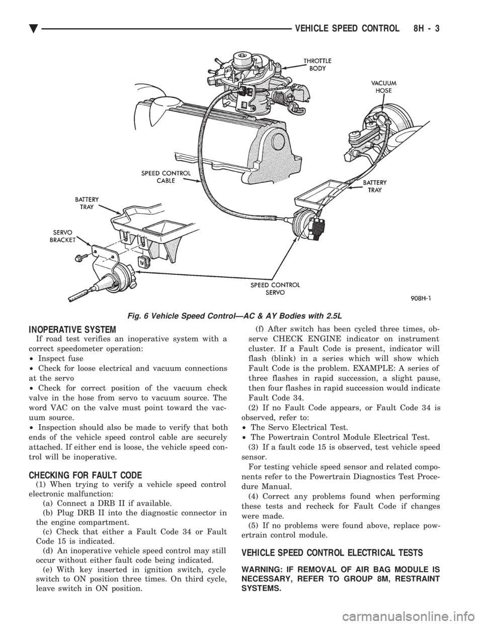
The vehicle speed control is electronically con-
trolled and vacuum operated. The electronic control
is integrated into the powertrain control module, lo-
cated next to battery. The controls are located on the
steering wheel and consist of the ON/OFF, RESUME/
ACCEL and SET/DECEL buttons (Fig. 1). For iden-
tification and location of the major components (Fig.
2 through 8).
The system is designed to operate at speeds above
35 mph (50 km/h).
WARNING: THE USE OF VEHICLE SPEED CON-
TROL IS NOT RECOMMENDED WHEN DRIVING
CONDITIONS DO NOT PERMIT MAINTAINING A
CONSTANT SPEED, SUCH AS IN HEAVY TRAFFIC
OR ON ROADS THAT ARE WINDING, ICY, SNOW
COVERED, OR SLIPPERY.
TO ACTIVATE: The ON/OFF button to the de-
pressed latched position, ON, the vehicle speed con-
trol function is now ready for use. TO DEACTIVATE:
A soft tap of the brake pedal,
normal brake application or depressing the clutch
pedal while the system is engaged will disengage ve-
hicle speed control without erasing memory. A sud-
den increase in engine rpm may be experienced if the
clutch pedal is depressed while the vehicle speed con-
trol is engaged. Pushing the ON/OFF button to the
unlatched position or turning off the ignition erases
the memory. TO SET SPEED: When the vehicle has reached
the desired speed push the SET/DECEL button to en-
gage system which will then automatically maintain
the desired speed. TO DECELERATE: When vehicle speed control is
engaged, holding the SET/DECEL button depressed
allows the vehicle to coast to a lower speed setting.
Fig. 1 Vehicle Speed Control Switch
Fig. 2 Vehicle Speed ControlÐ2.2L and 2.5L
Ä VEHICLE SPEED CONTROL 8H - 1
Page 605 of 2438

INOPERATIVE SYSTEM
If road test verifies an inoperative system with a
correct speedometer operation:
² Inspect fuse
² Check for loose electrical and vacuum connections
at the servo
² Check for correct position of the vacuum check
valve in the hose from servo to vacuum source. The
word VAC on the valve must point toward the vac-
uum source.
² Inspection should also be made to verify that both
ends of the vehicle speed control cable are securely
attached. If either end is loose, the vehicle speed con-
trol will be inoperative.
CHECKING FOR FAULT CODE
(1) When trying to verify a vehicle speed control
electronic malfunction: (a) Connect a DRB II if available.
(b) Plug DRB II into the diagnostic connector in
the engine compartment. (c) Check that either a Fault Code 34 or Fault
Code 15 is indicated. (d) An inoperative vehicle speed control may still
occur without either fault code being indicated. (e) With key inserted in ignition switch, cycle
switch to ON position three times. On third cycle,
leave switch in ON position. (f) After switch has been cycled three times, ob-
serve CHECK ENGINE indicator on instrument
cluster. If a Fault Code is present, indicator will
flash (blink) in a series which will show which
Fault Code is the problem. EXAMPLE: A series of
three flashes in rapid succession, a slight pause,
then four flashes in rapid succession would indicate
Fault Code 34.
(2) If no Fault Code appears, or Fault Code 34 is
observed, refer to:
² The Servo Electrical Test.
² The Powertrain Control Module Electrical Test.
(3) If a fault code 15 is observed, test vehicle speed
sensor. For testing vehicle speed sensor and related compo-
nents refer to the Powertrain Diagnostics Test Proce-
dure Manual. (4) Correct any problems found when performing
these tests and recheck for Fault Code if changes
were made. (5) If no problems were found above, replace pow-
ertrain control module.
VEHICLE SPEED CONTROL ELECTRICAL TESTS
WARNING: IF REMOVAL OF AIR BAG MODULE IS
NECESSARY, REFER TO GROUP 8M, RESTRAINT
SYSTEMS.
Fig. 6 Vehicle Speed ControlÐAC & AY Bodies with 2.5L
Ä VEHICLE SPEED CONTROL 8H - 3
Page 606 of 2438

Electronic vehicle speed control may be tested us-
ing two different methods. One involves use of a
DRB II. If this test method is desired, refer to the
Powertrain Diagnostic Test Procedures for charging
and vehicle speed control manual. The other test method uses a volt/ohm meter and is
described in the following tests. If any information is needed concerning wiring, re-
fer to Group 8W, Wiring Diagrams.
CAUTION: When test probing for voltage or conti-
nuity at electrical connectors, care must be taken
not to damage connector, terminals, or seals. If
these components are damaged, intermittent or
complete system failure may occur.
SERVO ELECTRICAL TESTS
WARNING: ON VEHICLES EQUIPPED WITH AIR-
BAG, SEE GROUP 8M, RESTRAINT SYSTEMS FOR
AIRBAG, STEERING WHEEL OR COLUMN RE-
MOVAL PROCEDURES.
(1) Turn ignition switch to the ON position. With
the vehicle speed control switch in the ON position,
set up a voltmeter to read battery voltage and con-
nect the negative lead to a good chassis ground. (2) Disconnect the four-way connector going to the
servo (Fig. 12). Test pin 2 of the main harness four-
way connector for battery voltage. If not OK go to
step 3. If voltage is OK go to step 4. (3) Perform the following tests.(a) Disconnect the six-way connector at the stop
lamp switch and test pin 1 of the main harness for
battery voltage. If voltage is OK perform the stop
lamp switch test. (b) If the stop lamp switch tests OK; repair wire
between the servo and the stop lamp switch. (c) If no voltage at pin 1 at the 6-way stop lamp
connector, remove the vehicle speed control switch
and disconnect the four-way connector. Test pin 1
of main harness for battery voltage. (d) If voltage is OK perform the vehicle speed
control switch test. (e) If vehicle speed control switch is OK, test
continuity across the clockspring. (f) If clockspring OK, repair as required, wire be-
tween stop lamp switch and clockspring. (g) If no voltage at pin 1 of the 4-way vehicle
speed control switch connector.
² Test for battery voltage between the ignition and
the fuse
² If voltage OK, check fuse
² If fuse OK, repair wire between fuse and clock-
spring
Fig. 7 Vehicle Speed ControlÐAC & AY Bodies with 3.0L
8H - 4 VEHICLE SPEED CONTROL Ä
Page 607 of 2438

(4) Connect a jumper wire between pin 2 of the
four-way servo connector of the main harness and
pin 2 of the vehicle speed control servo (Fig. 12). The
other three pins from the servo should show battery
voltage. If not, replace the servo. (5) Using an ohmmeter, connect one lead to a good
body ground and the other lead touch pin 1 in the
four-way servo connector of the main harness. The
meter should show continuity. If not, repair the
ground circuit as necessary.
POWERTRAIN CONTROL MODULE ELECTRICAL
TEST
WARNING: ON VEHICLES EQUIPPED WITH AIR-
BAG, SEE GROUP 8M, RESTRAINT SYSTEMS FOR
AIRBAG, STEERING WHEEL OR COLUMN RE-
MOVAL PROCEDURES.
(1) Unplug 60-way connector from the powertrain
control module, located next to the battery (Fig. 13). (2) Remove vehicle speed control switch. Refer to
Vehicle Speed Control Switch Removal. Disconnect
the 4-way connector. (3) Using an ohmmeter test continuity between pin
23 of powertrain control module and pin 4 of the ve-
hicle speed control switch harness. Refer to Fig. 14
for controller terminal locations. (a) If no continuity, repair wire circuit as neces-
sary. (b) Continuity OK, refer to Vehicle Speed Con-
trol Switch Test.
(4) Connect the 4-way connector to vehicle speed
control switch. (5) Connect negative lead of voltmeter to a good
body ground near the powertrain control module. (6) Turn ignition switch ON.
(7) Place vehicle speed control switch in the OFF
position. Touch the positive lead of the voltmeter to
pin 53, the voltmeter should read 0 volts. (8) Place vehicle speed control switch in the ON
position. Touch the positive lead of the voltmeter to
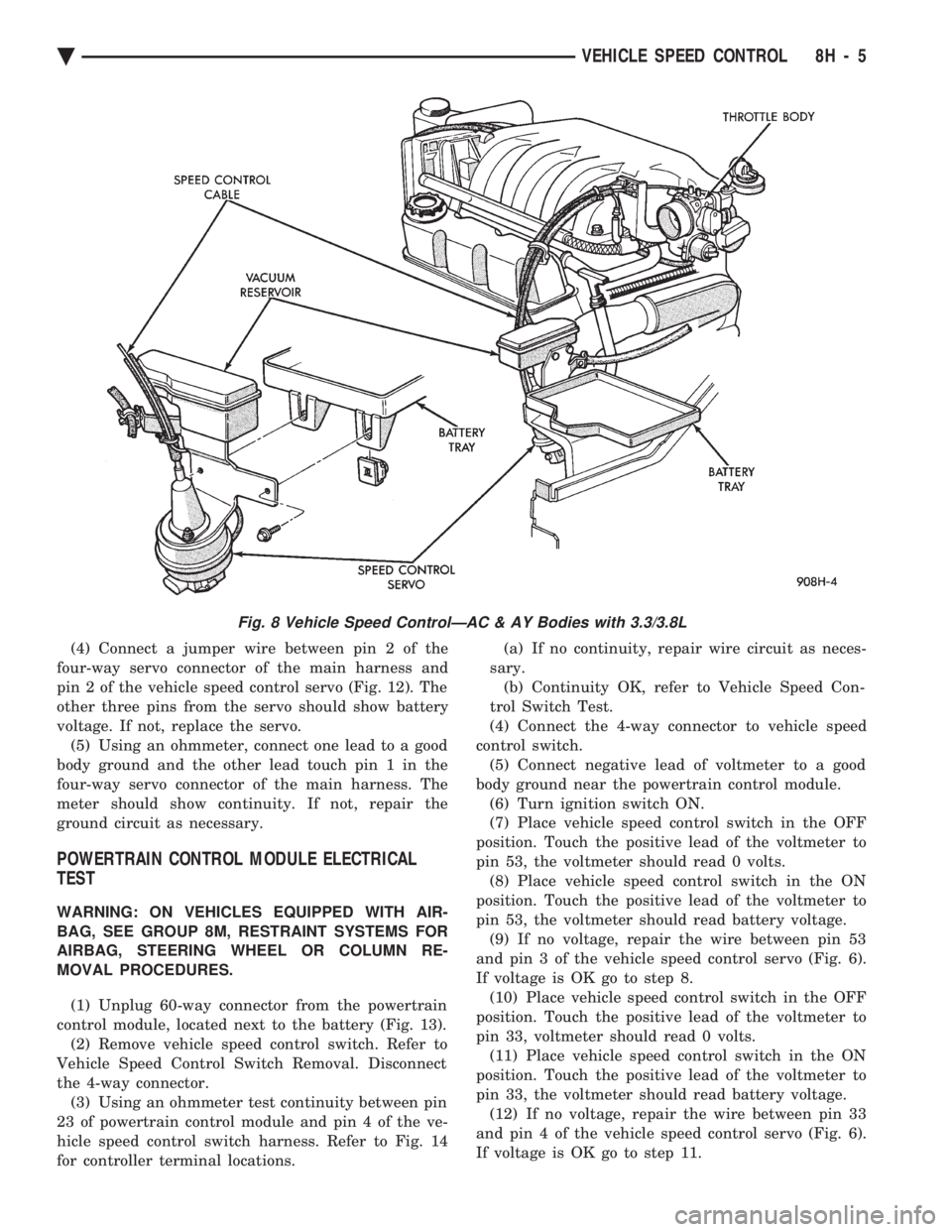
pin 53, the voltmeter should read battery voltage. (9) If no voltage, repair the wire between pin 53
and pin 3 of the vehicle speed control servo (Fig. 6).
If voltage is OK go to step 8. (10) Place vehicle speed control switch in the OFF
position. Touch the positive lead of the voltmeter to
pin 33, voltmeter should read 0 volts. (11) Place vehicle speed control switch in the ON
position. Touch the positive lead of the voltmeter to
pin 33, the voltmeter should read battery voltage. (12) If no voltage, repair the wire between pin 33
and pin 4 of the vehicle speed control servo (Fig. 6).
If voltage is OK go to step 11.
Fig. 8 Vehicle Speed ControlÐAC & AY Bodies with 3.3/3.8L
Ä VEHICLE SPEED CONTROL 8H - 5
Page 612 of 2438

(4) Disconnect electrical connector and vacuum
hose. (5) Pull cable away from servo to expose retaining
clip and remove clip attaching cable to servo.
INSTALLATION
(1) With throttle in full open position align hole in
vehicle speed control cable sleeve with hole in servo
pin and install retaining clip. (2) Connect vacuum hose to servo.
(3) Connect electrical connector.
(4) Position mounting bracket and install screws
attaching bracket and tighten to 12 N Im (105 in.
lbs.) torque. (5) Insert servo studs through holes in vehicle
speed control cable and mounting bracket. (6) Install nuts, tighten to 7 N Im (60 in. lbs.)
torque.
VEHICLE SPEED CONTROL SWITCH REMOVAL
The vehicle speed control switch is mounted in the
steering wheel and wired through the clock spring
device under the steering wheel hub (Fig.1).
WARNING: IF REMOVAL OF AIR BAG MODULE IS
NECESSARY, REFER TO GROUP 8M, RESTRAINT
SYSTEMS.
REMOVAL
(1) Turn off ignition.
(2) Remove two screws from back side of steering
wheel. (3) Rock switch away from air bag or horn pad
while lifting switch out of steering wheel. (4) Disconnect 4-way electrical connector.
INSTALLATION
(1) Turn off ignition.
(2) Connect 4-way electrical connector from clock
spring to switch. (3) Place switch in steering wheel, sliding the for-
ward edge of switch under air bag or horn pad. Line
up locating pins on switch with holes in steering
wheel frame. (4) Attach switch to wheel with two screws start-
ing with the screw at the left end of the switch.
8H - 10 VEHICLE SPEED CONTROL Ä