1993 CHEVROLET PLYMOUTH ACCLAIM ignition
[x] Cancel search: ignitionPage 501 of 2438

(3) When testing temperature, allow the engine to
run until the vehicle reaches a normal operating
temperature. Turn ignition OFF, and remove gauge
from cluster. (a) Testing oil pressure gauge, engine needs to
be running. (b) Measure and record the resistance between
sending unit pin and ground pin of the gauge in
question. Refer to Gauge Calibration. (c) It is important to have the same engine tem-
perature and engine speed when checking temper-
ature and oil pressure gauges position. The time
between gauge position reading and sending unit
measuring should be kept to a minimum. (d) If resistance and gauge position are not sim-
ilar, replace gauge. (e) If OK, test resistance from the sending unit
to the cluster connector. (f) If resistance reading is different, check
printed circuit board for contact to cluster connec-
tor. (g) If OK and contacts are not distorted, replace
printed circuit board. (h) If everything checks out OK, refer to sending
unit test.
(4) If fuel gauge does not meet specifications, refer
to Group 14, Fuel for the test procedure.
GAUGE CALIBRATION
(1) Remove the gauge.
(2) Check for ignition voltage and ground to the
gauge. (3) With the ignition key in the OFF position, re-
place gauge. Turn the ignition key to the ON posi-
tion. To test oil pressure gauge engine must be
running. When testing oil or temperature gauge the
engine should be at normal operating temperature.
Record the gauge position. (4) Remove gauge and record the resistance be-
tween the sending unit pin and the gauge ground
pin. When checking gauges, it is important to have
the same engine temperature and speed when noting
gauge position. The time between gauge reading and
measuring should be kept to a minimum. (5) The Gauge Resistance Chart (Fig. 24), is gen-
eral guidelines for checking the gauge position
against the sending unit resistance. Because of only a few specific points of gauge posi-
tion versus sending unit resistance, a good estimate
is need when the resistance falls between gradua-
tions. Even when the resistance corresponds to grad-
uations, the gauge has a tolerance of 64 ohms.
Volt gauge: The calibration dot on the volt gauge
corresponds to 13 volts between the gauge ignition
and ground pins. If voltage varies from this, estimate
proper gauge position with input voltage.
TACHOMETER REPLACEMENT
(1) Remove cluster, radio and rear window defog-
ger bezels and mask/lens assembly. (2) Remove screws attaching tachometer to cluster
housing. (3) Pull tachometer rearward to remove.
(4) For installation reverse above procedures.
TACHOMETER CIRCUIT TESTING
(1) Remove cluster, radio and rear window defog-
ger bezels and mask/lens assembly. (2) Check for battery voltage at cavity A of the in-
strument cluster black connector. (3) With the ignition in the ON position, check for
battery voltage at cavity C of the black connector
(Fig. 25).
Fig. 24 Gauge Resistance
Fig. 25 Printed Circuit Board 11-Way Connector
Ä INSTRUMENT PANEL AND GAUGES 8E - 9
Page 503 of 2438

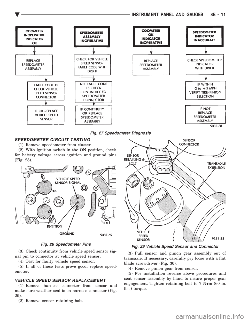
SPEEDOMETER CIRCUIT TESTING
(1) Remove speedometer from cluster.
(2) With ignition switch in the ON position, check
for battery voltage across ignition and ground pins
(Fig. 28).
(3) Check continuity from vehicle speed sensor sig-
nal pin to connector at vehicle speed sensor. (4) Test for faulty vehicle speed sensor.
(5) If all of these tests prove good, replace speed-
ometer.
VEHICLE SPEED SENSOR REPLACEMENT
(1) Remove harness connector from sensor and
make sure weather seal is on harness connector (Fig.
29). (2) Remove sensor retaining bolt. (3) Pull sensor and pinion gear assembly out of
transaxle. If necessary, carefully pry loose with a flat
blade screwdriver (Fig. 30). (4) Remove pinion gear from sensor.
(5) For installation reverse above procedures and
seat sensor assembly by hand to insure proper gear
engagement. Tighten retaining bolt to 7 N Im (60 in.
lbs.) torque.
Fig. 27 Speedometer Diagnosis
Fig. 28 Speedometer PinsFig. 29 Vehicle Speed Sensor and Connector
Ä INSTRUMENT PANEL AND GAUGES 8E - 11
Page 505 of 2438

(3) Remove lamp sockets as necessary by turning
them counterclockwise (Fig. 34 and 35).
PRINTED CIRCUIT BOARD REPLACEMENT
(1) Remove cluster assembly.
(2) Remove tachometer drive module, low fuel re-
lay and gauge alert module (Fig. 32). (3) Remove all cluster lamps.
(4) Remove mounting screws securing printed cir-
cuit board to cluster housing (Fig. 34). (5) For installation reverse above procedures.
ELECTRONIC CLUSTER
SELF DIAGNOSTIC SYSTEM
The electronic clusters (Fig. 36) have an internal
diagnostics routing to isolate problems within the
cluster or sending units. Using the cluster Self-Diagnostic Test will deter-
mine whether problem is within cluster or outside of
cluster (Fig. 37 and 38). Successful completion of the SELF DIAGNOSTIC
TEST indicates that the problem is in the connectors
or sensors outside of the module. Refer to Fig. 39 for
terminal listing.
CONDITION: CLUSTER DISPLAYS DO NOT ILLUMINATE AFTER VEHICLE IS STARTED
PROCEDURE
(1) Check fuses and verify battery and ignition
voltage at cluster connector. (2) Check ground from cluster connector to instru-
ment panel ground stud. (3) Check lamps, replace if necessary.
Fig. 34 Mechanical Cluster Lamp Location
Fig. 33 Gauge Alert Module
Ä INSTRUMENT PANEL AND GAUGES 8E - 13
Page 507 of 2438

CONDITION: SPEEDOMETER AND ODOMETER ARE INOPERATIVE OR OPERATESINTERMITTENTLY
PROCEDURE
Check for defective vehicle speed sensor wiring.
CONDITION: OIL GAUGE, FUEL GAUGE, TEMPERATURE GAUGE, OR VOLTAGE GAUGEINOPERATIVE
PROCEDURE
Check for defective sending unit or wiring: (a) Sending units and wiring can be checked by
grounding the connector leads, at the sending unit,
in the vehicle. (b) With the ignition in the ON position, a
grounded input will cause the oil, fuel, or temper-
ature gauge to read maximum.
CONDITION: CLUSTER DISPLAY DOES NOT DIM WHEN HEADLAMP SWITCH ISACTIVATED AND RHEOSTAT ROTATED
PROCEDURE
(1) Check fuses in headlamp circuit.
(2) Check for loose connections or defective wiring
from headlamp switch to the cluster. (3) Check for defective headlamp switch.
(4) The electronic instrument cluster requires both
a marker feed and illumination feed to operate cor-
rectly.
SWITCH AND PANEL COMPONENT SERVICE
HEADLAMP/FOG LAMP SWITCH REPLACEMENT
(1) Remove cluster bezel (Fig. 40).
(2) Remove three screws securing headlamp switch
mounting plate to base panel (Fig. 41). (3) Pull headlamp/fog lamp switch mounting plate
rearward. Disconnect wiring connectors from head-
lamp switch and fog lamp switch pigtail (Fig. 42). (4) Remove knob and stem by depressing button on
bottom of the switch (Fig. 43). (5) Snap-out escutcheon.
(6) Remove fog lamp switch from escutcheon.
(7) Remove nut that attaches headlamp switch to
mounting plate (Fig. 44). (8) For installation reverse above procedures.
FOG LAMP SWITCH TEST
(1) Remove the fog lamp switch from mounting lo-
cation. (2) Disconnect the wiring harness from the switch
pigtail. (3) Using a Ohmmeter, test for continuity between
the terminals of the switch pigtail (Fig. 45). (4) If not OK, replace switch.
LOWER STEERING COLUMN COVERREPLACEMENT
(1) Disconnect park brake release rod from park
brake. (2) Remove fuse box access door and remove screw
from lower column cover (Fig. 46). (3) Remove screws from lower cover, four across
the top and two on bottom. (4) Remove lower steering column cover.
(5) For installation reverse above procedures.
LEFT LOWER INSTRUMENT PANEL SILENCER REPLACEMENT
(1) Remove screws from front of silencer (Fig. 47).
(2) Remove push nut.
(3) Remove silencer.
(4) For installation reverse above procedures.
RIGHT LOWER INSTRUMENT PANEL SILENCER REPLACEMENT
(1) On floor shift vehicles, remove console assem-
bly and center brace bracket. (2) On column shift vehicles, remove center brace
bracket. (3) Remove screws from front of silencer (Fig. 47).
(4) Remove three push nuts from rear of silencer.
(5) Remove lower right silencer.
(6) For installation reverse above procedures.
GLOVE BOX ASSEMBLY REPLACEMENT
(1) Disconnect battery negative cable and isolate
or remove fuse #2 prior to removing switch or wires
may short to ground. (2) Open glove box door and disconnect check
strap. (3) Remove glove box light and switch by squeez-
ing retaining tabs from behind switch mount and
slide rearward. Disconnect wiring connectors. (4) Remove 11 screws from glove box assembly
(Fig. 48). (5) Remove glove box assembly.
Fig. 36 Electronic Cluster
Ä INSTRUMENT PANEL AND GAUGES 8E - 15
Page 515 of 2438

AC AND AY BODIES INDEX
page page
Electronic Cluster ........................ 34
Gauges ................................ 28
General Information ....................... 23
Interior Lamp Replacement ................. 41 Mechanical Cluster and Gauge Service
........ 24
Mechanical/Electronic Cluster Removal ........ 25
Switch and Panel Component Service ......... 37
GENERAL INFORMATION
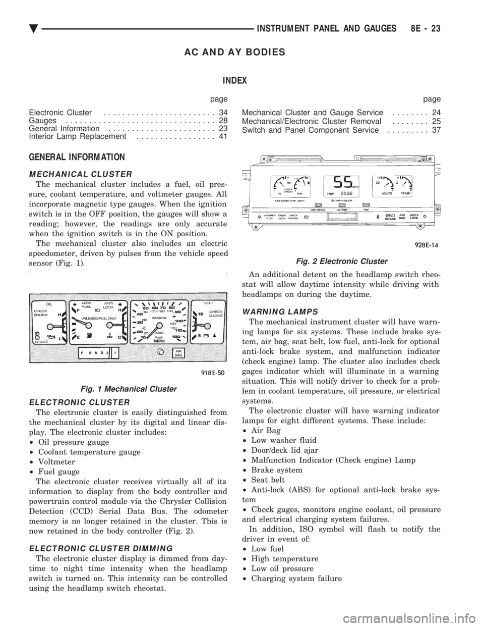
MECHANICAL CLUSTER
The mechanical cluster includes a fuel, oil pres-
sure, coolant temperature, and voltmeter gauges. All
incorporate magnetic type gauges. When the ignition
switch is in the OFF position, the gauges will show a
reading; however, the readings are only accurate
when the ignition switch is in the ON position. The mechanical cluster also includes an electric
speedometer, driven by pulses from the vehicle speed
sensor (Fig. 1).
ELECTRONIC CLUSTER
The electronic cluster is easily distinguished from
the mechanical cluster by its digital and linear dis-
play. The electronic cluster includes:
² Oil pressure gauge
² Coolant temperature gauge
² Voltmeter
² Fuel gauge
The electronic cluster receives virtually all of its
information to display from the body controller and
powertrain control module via the Chrysler Collision
Detection (CCD) Serial Data Bus. The odometer
memory is no longer retained in the cluster. This is
now retained in the body controller (Fig. 2).
ELECTRONIC CLUSTER DIMMING
The electronic cluster display is dimmed from day-
time to night time intensity when the headlamp
switch is turned on. This intensity can be controlled
using the headlamp switch rheostat. An additional detent on the headlamp switch rheo-
stat will allow daytime intensity while driving with
headlamps on during the daytime.
WARNING LAMPS
The mechanical instrument cluster will have warn-
ing lamps for six systems. These include brake sys-
tem, air bag, seat belt, low fuel, anti-lock for optional
anti-lock brake system, and malfunction indicator
(check engine) lamp. The cluster also includes check
gages indicator which will illuminate in a warning
situation. This will notify driver to check for a prob-
lem in coolant temperature, oil pressure, or electrical
systems. The electronic cluster will have warning indicator
lamps for eight different systems. These include:
² Air Bag
² Low washer fluid
² Door/deck lid ajar
² Malfunction Indicator (Check engine) Lamp
² Brake system
² Seat belt
² Anti-lock (ABS) for optional anti-lock brake sys-
tem
² Check gages, monitors engine coolant, oil pressure
and electrical charging system failures. In addition, ISO symbol will flash to notify the
driver in event of:
² Low fuel
² High temperature
² Low oil pressure
² Charging system failure
Fig. 1 Mechanical Cluster
Fig. 2 Electronic Cluster
Ä INSTRUMENT PANEL AND GAUGES 8E - 23
Page 516 of 2438

MESSAGE CENTER
The message center is a car graphic warning lamp
module. This conventional warning system and lo-
cated above the headlamp switch.
ELECTRONIC DIGITAL CLOCK
The electronic digital clock is in the radio. The
clock and radio each use the display panel built into
the radio. A digital readout indicates the time in
hours and minutes whenever the ignition switch is in
the ON or ACC position. When the ignition switch is in the OFF position, or
when the radio frequency is being displayed, time
keeping is accurately maintained. The procedure for setting the clock varies slightly
with each radio. The correct procedure is described
under the individual radio operating instructions re-
ferred to in the Owner's Manual supplied with the
vehicle.
AIR BAG WARNING SYSTEM
For testing of this system refer to Group 8M, Re-
straint Systems.
MECHANICAL CLUSTER AND GAUGE SERVICE
CAUTION: Disconnect negative battery cable, in en-
gine compartment, before servicing instrument
panel. When power is required for test purposes,
reconnect battery cable for the test only.
Disconnect negative battery cable after test and be-
fore continuing service procedures.
SENDING UNIT TEST
When a problem occurs with a cluster gauge, be-
fore disassembling the cluster to check the gauge,
check for a defective sending unit or wiring. (1) Sending units and wiring can be checked by
grounding the connector leads, at the sending unit,
in the vehicle. (2) With the ignition in the ON position; a
grounded input will cause the oil, fuel or tempera-
ture gauge to read at or above maximum.
CHECK GAUGES WARNING LAMP TESTS
The check gauges warning lamp is illuminated by
the low oil pressure sending unit switch or the body
controller when there is high temperature or charg-
ing system failure. To test the lamp, turn ignition key to the ON po-
sition without starting the vehicle. The low oil pres-
sure switch is grounded and the light will be on
indefinitely. If the lamp fails to light, pull the cluster and check
the following: (a) Continuity between ground and check gauge
pin J (Fig. 3). (b) Proper contact between the gauge pins and
wiring harness and printed circuit board pins. (c) If there is ground and proper pin contact, re-
place lamp. (d) If there is no continuity, check the low oil
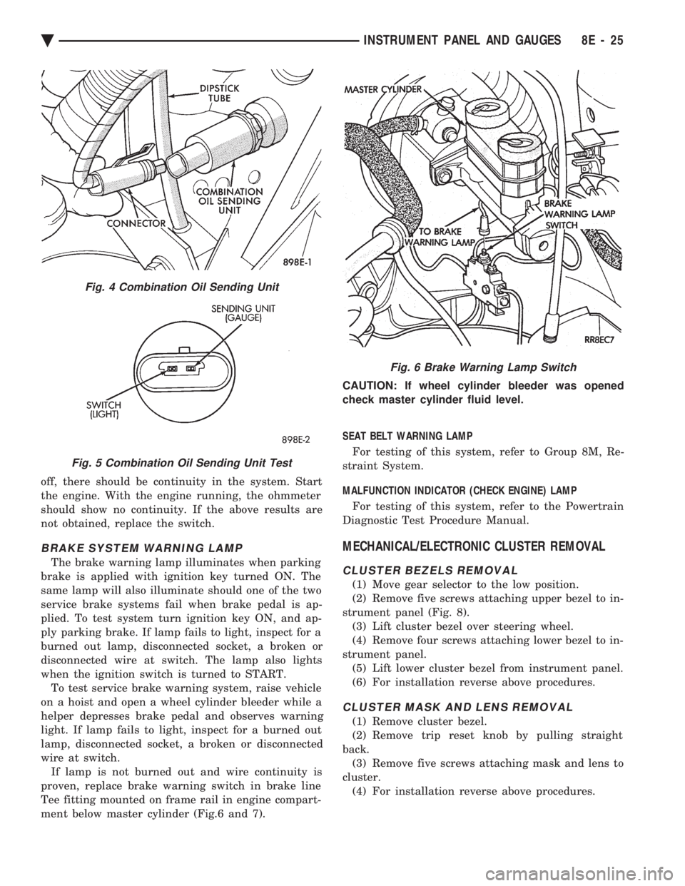
pressure sending unit switch (Fig. 4 and 5).
To test the switch disconnect the switch electrical
connector. Attach positive lead of an ohmmeter to
the switch terminal for the gray (GY) wire and the
negative lead to an engine ground. With the engine
Fig. 3 Mechanical Cluster Connectors
8E - 24 INSTRUMENT PANEL AND GAUGES Ä
Page 517 of 2438

off, there should be continuity in the system. Start
the engine. With the engine running, the ohmmeter
should show no continuity. If the above results are
not obtained, replace the switch.
BRAKE SYSTEM WARNING LAMP
The brake warning lamp illuminates when parking
brake is applied with ignition key turned ON. The
same lamp will also illuminate should one of the two
service brake systems fail when brake pedal is ap-
plied. To test system turn ignition key ON, and ap-
ply parking brake. If lamp fails to light, inspect for a
burned out lamp, disconnected socket, a broken or
disconnected wire at switch. The lamp also lights
when the ignition switch is turned to START. To test service brake warning system, raise vehicle
on a hoist and open a wheel cylinder bleeder while a
helper depresses brake pedal and observes warning
light. If lamp fails to light, inspect for a burned out
lamp, disconnected socket, a broken or disconnected
wire at switch. If lamp is not burned out and wire continuity is
proven, replace brake warning switch in brake line
Tee fitting mounted on frame rail in engine compart-
ment below master cylinder (Fig.6 and 7). CAUTION: If wheel cylinder bleeder was opened
check master cylinder fluid level.
SEAT BELT WARNING LAMP
For testing of this system, refer to Group 8M, Re-
straint System.
MALFUNCTION INDICATOR (CHECK ENGINE) LAMP
For testing of this system, refer to the Powertrain
Diagnostic Test Procedure Manual.
MECHANICAL/ELECTRONIC CLUSTER REMOVAL
CLUSTER BEZELS REMOVAL
(1) Move gear selector to the low position.
(2) Remove five screws attaching upper bezel to in-
strument panel (Fig. 8). (3) Lift cluster bezel over steering wheel.
(4) Remove four screws attaching lower bezel to in-
strument panel. (5) Lift lower cluster bezel from instrument panel.
(6) For installation reverse above procedures.
CLUSTER MASK AND LENS REMOVAL
(1) Remove cluster bezel.
(2) Remove trip reset knob by pulling straight
back. (3) Remove five screws attaching mask and lens to
cluster. (4) For installation reverse above procedures.
Fig. 4 Combination Oil Sending Unit
Fig. 5 Combination Oil Sending Unit Test
Fig. 6 Brake Warning Lamp Switch
Ä INSTRUMENT PANEL AND GAUGES 8E - 25
Page 520 of 2438

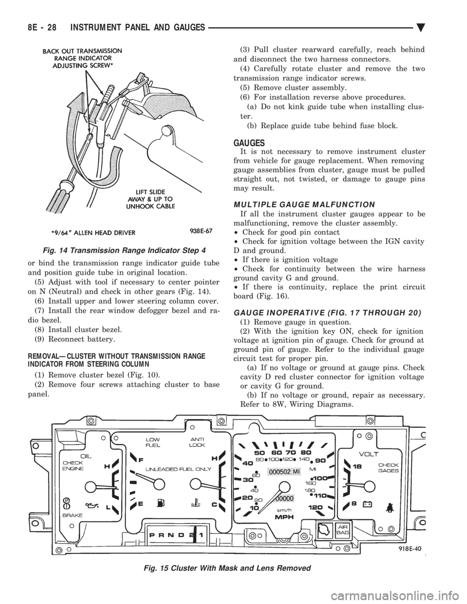
or bind the transmission range indicator guide tube
and position guide tube in original location.(5) Adjust with tool if necessary to center pointer
on N (Neutral) and check in other gears (Fig. 14). (6) Install upper and lower steering column cover.
(7) Install the rear window defogger bezel and ra-
dio bezel. (8) Install cluster bezel.
(9) Reconnect battery.
REMOVALÐCLUSTER WITHOUT TRANSMISSION RANGE
INDICATOR FROM STEERING COLUMN
(1) Remove cluster bezel (Fig. 10).
(2) Remove four screws attaching cluster to base
panel. (3) Pull cluster rearward carefully, reach behind
and disconnect the two harness connectors. (4) Carefully rotate cluster and remove the two
transmission range indicator screws. (5) Remove cluster assembly.
(6) For installation reverse above procedures. (a) Do not kink guide tube when installing clus-
ter. (b) Replace guide tube behind fuse block.
GAUGES
It is not necessary to remove instrument cluster
from vehicle for gauge replacement. When removing
gauge assemblies from cluster, gauge must be pulled
straight out, not twisted, or damage to gauge pins
may result.
MULTIPLE GAUGE MALFUNCTION
If all the instrument cluster gauges appear to be
malfunctioning, remove the cluster assembly.
² Check for good pin contact
² Check for ignition voltage between the IGN cavity
D and ground.
² If there is ignition voltage
² Check for continuity between the wire harness
ground cavity G and ground.
² If there is continuity, replace the print circuit
board (Fig. 16).
GAUGE INOPERATIVE (FIG. 17 THROUGH 20)
(1) Remove gauge in question.
(2) With the ignition key ON, check for ignition
voltage at ignition pin of gauge. Check for ground at
ground pin of gauge. Refer to the individual gauge
circuit test for proper pin. (a) If no voltage or ground at gauge pins. Check
cavity D red cluster connector for ignition voltage
or cavity G for ground. (b) If no voltage or ground, repair as necessary.
Refer to 8W, Wiring Diagrams.
Fig. 15 Cluster With Mask and Lens Removed
Fig. 14 Transmission Range Indicator Step 4
8E - 28 INSTRUMENT PANEL AND GAUGES Ä