1993 CHEVROLET PLYMOUTH ACCLAIM window
[x] Cancel search: windowPage 497 of 2438

MECHANICAL/ELECTRONIC CLUSTER REMOVAL
CLUSTER BEZEL REMOVAL
(1) On column shift vehicles, place column shifter
to neutral position. (2) On tilt steering column vehicles, adjust tilt
range to lowest position. (3) Pull cluster bezel rearward to disengage 11
clips (Fig. 10).
(4) Remove cluster bezel.
(5) For installation reverse above procedures.
CLUSTER MASK AND LENS REMOVAL
(1) Remove cluster, radio and rear window defog-
ger bezels (Fig. 10). (2) Remove four cluster to panel screws.
(3) Pull cluster assembly rearward. Vehicles with
column shift use care to not damage transmission
range indicator guide tube. (4) Remove four screws holding the cluster mask to
cluster housing (Fig. 11).
(5) Pull cluster mask and lens rearward to remove.
(6) For installation reverse above procedures.
CLUSTER ASSEMBLY
REMOVALÐCLUSTER WITH TRANSMISSION RANGE
INDICATOR FROM STEERING COLUMN
(1) Disconnect battery to assure no air bag system
fault codes are stored. (2) Remove cluster bezel (Fig. 10).
(3) On column shift vehicle: (Fig. 12 through 15).
(a) Remove lower steering column cover (Fig.
16). Release guide tube from behind fuse block.
Fig. 10 Cluster Bezel
Fig. 11 Cluster Mask and Lens
Fig. 12 Transmission Range Indicator Step 1
Fig. 13 Transmission Range Indicator Step 2
Ä INSTRUMENT PANEL AND GAUGES 8E - 5
Page 498 of 2438
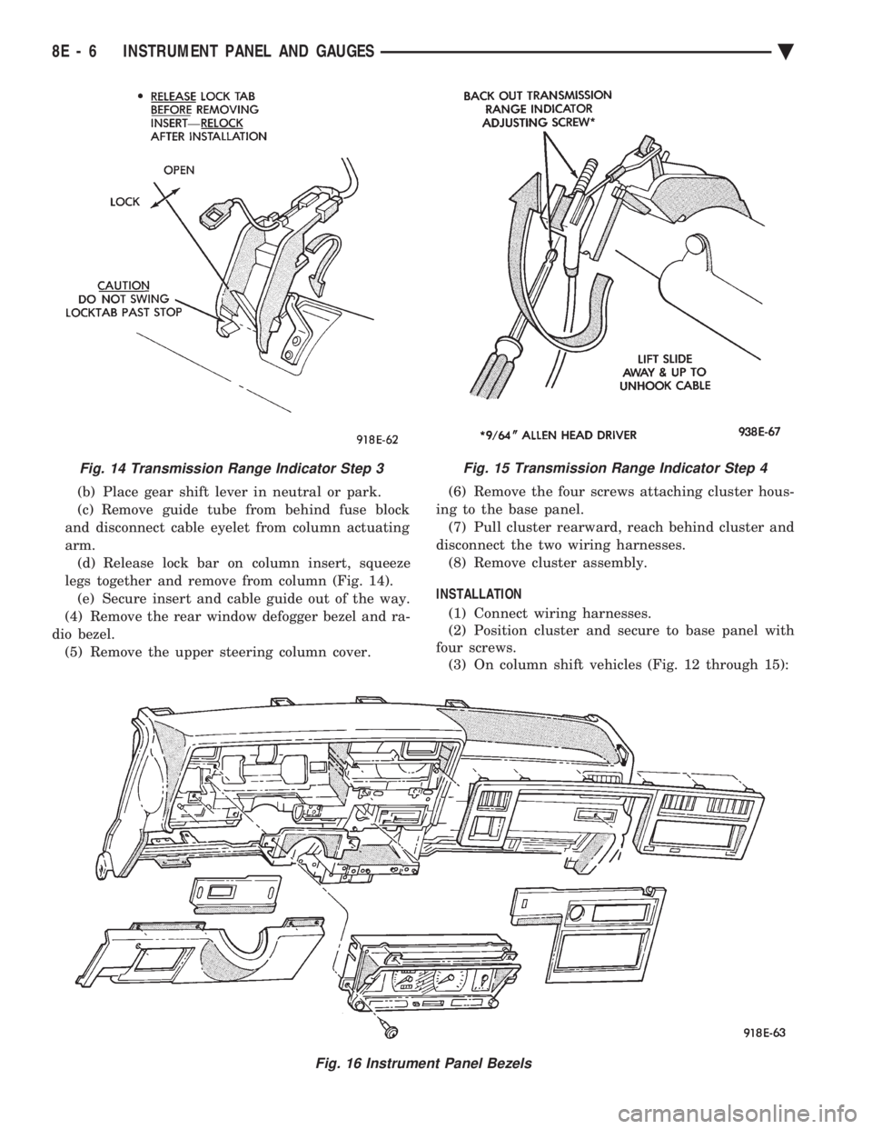
(b) Place gear shift lever in neutral or park.
(c) Remove guide tube from behind fuse block
and disconnect cable eyelet from column actuating
arm. (d) Release lock bar on column insert, squeeze
legs together and remove from column (Fig. 14). (e) Secure insert and cable guide out of the way.
(4) Remove the rear window defogger bezel and ra-
dio bezel. (5) Remove the upper steering column cover. (6) Remove the four screws attaching cluster hous-
ing to the base panel. (7) Pull cluster rearward, reach behind cluster and
disconnect the two wiring harnesses. (8) Remove cluster assembly.
INSTALLATION (1) Connect wiring harnesses.
(2) Position cluster and secure to base panel with
four screws. (3) On column shift vehicles (Fig. 12 through 15):
Fig. 15 Transmission Range Indicator Step 4
Fig. 16 Instrument Panel Bezels
Fig. 14 Transmission Range Indicator Step 3
8E - 6 INSTRUMENT PANEL AND GAUGES Ä
Page 499 of 2438

(a) Route transmission range indicator guide as-
sembly under left steering column wing and down
left side of column (Fig. 12). (b) Insert flange of column insert into column,
squeeze legs together with tabs under column
jacket and engage lock bar to secure insert (Fig.
14). (c) Hook cable eyelet to steering column actuator
check pointer, should indicate neutral. Do not kink
or bind transmission range indicator guide tube
and position guide tube in original location. (d) Adjust with tool if necessary to center pointer
on N (Neutral) and check in other gears (Fig. 15).
(4) Install upper and lower steering column cover.
(5) Install the rear window defogger bezel and ra-
dio bezel. (6) Install cluster bezel.
(7) Reconnect battery.
REMOVALÐCLUSTER WITHOUT TRANSMISSION RANGE
INDICATOR FROM STEERING COLUMN (1) Remove cluster bezel (Fig. 10).
(2) Remove four screws attaching cluster to base
panel. (3) Pull cluster rearward carefully, reach behind
and disconnect the two harness connectors. (4) Carefully rotate cluster and remove the two
transmission range indicator screws. (5) Remove cluster assembly.
(6) For installation reverse above procedures. (a) Do not kink guide tube when installing clus-
ter. (b) Replace guide tube behind fuse block.
GAUGES
It is not necessary to remove instrument clus-
ter assembly from vehicle for gauge replace-
ment. When removing gauge assemblies from cluster,
gauge must be pulled straight out, not twisted, or
damage to gauge pin may result.
MULTIPLE GAUGE MALFUNCTION
If the fuel, voltage and tachometer gauges appear
to be malfunctioning, remove the cluster assembly.
Check for good pin contact between the wire harness
and printed circuit board. If there is good contact,
check for ignition voltage at ignition cavity C of the
black connector. If there is ignition voltage, check for
continuity between the wire harness ground cavity H
of the black connector and ground. If there is conti-
nuity, replace printed circuit board. If the temperature, oil pressure and speedometer
gauges appear to be malfunctioning remove the clus-
ter assembly. Check for a good contact between the
wire harness and the printed circuit board. If there is
good contact, check for ignition voltage at cavity J of
the red connector. If there is voltage, check for con- tinuity at cavity H of the black connector. If there is
continuity, replace the printed circuit board.
If the temperature, fuel, voltage and speedometer
gauges appear to be malfunctioning, remove the clus-
ter assembly. Check for good pin contact between the
wire harness and the printed circuit board. If there is
good contact, check ignition voltage at cavity J of the
red connector. If there is voltage, check for continuity
at cavity H of the black connector. If there is conti-
nuity, replace the printed circuit board.
GAUGE INOPERATIVE (FIG. 17 THROUGH 23)
(1) Remove gauge in question.
Fig. 17 Fuel Gauge PinsÐWith Tachometer
Fig. 18 Fuel Gauge PinsÐWithout Tachometer
Ä INSTRUMENT PANEL AND GAUGES 8E - 7
Page 501 of 2438

(3) When testing temperature, allow the engine to
run until the vehicle reaches a normal operating
temperature. Turn ignition OFF, and remove gauge
from cluster. (a) Testing oil pressure gauge, engine needs to
be running. (b) Measure and record the resistance between
sending unit pin and ground pin of the gauge in
question. Refer to Gauge Calibration. (c) It is important to have the same engine tem-
perature and engine speed when checking temper-
ature and oil pressure gauges position. The time
between gauge position reading and sending unit
measuring should be kept to a minimum. (d) If resistance and gauge position are not sim-
ilar, replace gauge. (e) If OK, test resistance from the sending unit
to the cluster connector. (f) If resistance reading is different, check
printed circuit board for contact to cluster connec-
tor. (g) If OK and contacts are not distorted, replace
printed circuit board. (h) If everything checks out OK, refer to sending
unit test.
(4) If fuel gauge does not meet specifications, refer
to Group 14, Fuel for the test procedure.
GAUGE CALIBRATION
(1) Remove the gauge.
(2) Check for ignition voltage and ground to the
gauge. (3) With the ignition key in the OFF position, re-
place gauge. Turn the ignition key to the ON posi-
tion. To test oil pressure gauge engine must be
running. When testing oil or temperature gauge the
engine should be at normal operating temperature.
Record the gauge position. (4) Remove gauge and record the resistance be-
tween the sending unit pin and the gauge ground
pin. When checking gauges, it is important to have
the same engine temperature and speed when noting
gauge position. The time between gauge reading and
measuring should be kept to a minimum. (5) The Gauge Resistance Chart (Fig. 24), is gen-
eral guidelines for checking the gauge position
against the sending unit resistance. Because of only a few specific points of gauge posi-
tion versus sending unit resistance, a good estimate
is need when the resistance falls between gradua-
tions. Even when the resistance corresponds to grad-
uations, the gauge has a tolerance of 64 ohms.
Volt gauge: The calibration dot on the volt gauge
corresponds to 13 volts between the gauge ignition
and ground pins. If voltage varies from this, estimate
proper gauge position with input voltage.
TACHOMETER REPLACEMENT
(1) Remove cluster, radio and rear window defog-
ger bezels and mask/lens assembly. (2) Remove screws attaching tachometer to cluster
housing. (3) Pull tachometer rearward to remove.
(4) For installation reverse above procedures.
TACHOMETER CIRCUIT TESTING
(1) Remove cluster, radio and rear window defog-
ger bezels and mask/lens assembly. (2) Check for battery voltage at cavity A of the in-
strument cluster black connector. (3) With the ignition in the ON position, check for
battery voltage at cavity C of the black connector
(Fig. 25).
Fig. 24 Gauge Resistance
Fig. 25 Printed Circuit Board 11-Way Connector
Ä INSTRUMENT PANEL AND GAUGES 8E - 9
Page 502 of 2438
(4) Check cavity H of the black connector for con-
tinuity to ground. (5) Check for tachometer signal from the power-
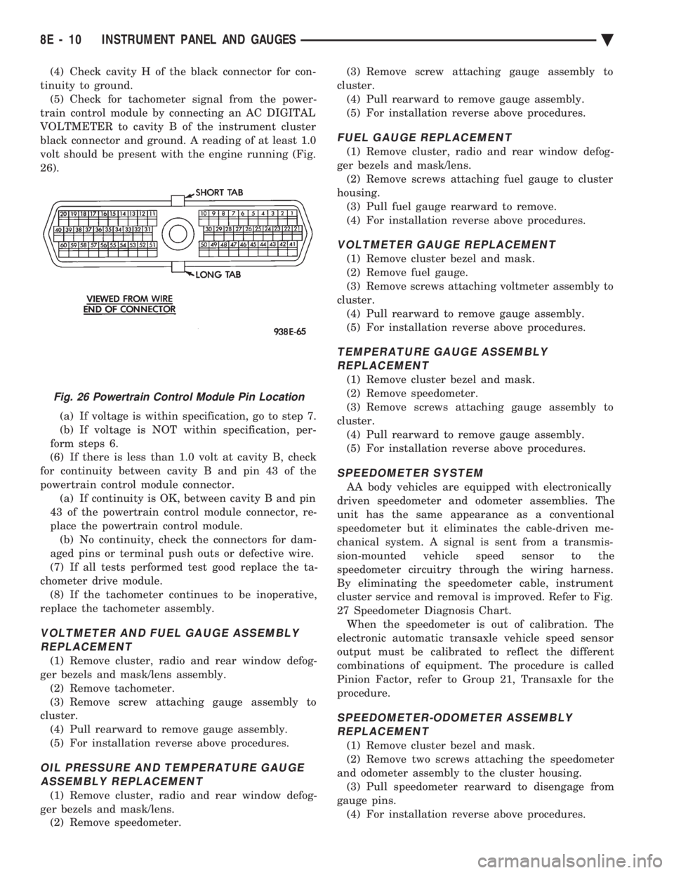
train control module by connecting an AC DIGITAL
VOLTMETER to cavity B of the instrument cluster
black connector and ground. A reading of at least 1.0
volt should be present with the engine running (Fig.
26).
(a) If voltage is within specification, go to step 7.
(b) If voltage is NOT within specification, per-
form steps 6.
(6) If there is less than 1.0 volt at cavity B, check
for continuity between cavity B and pin 43 of the
powertrain control module connector. (a) If continuity is OK, between cavity B and pin
43 of the powertrain control module connector, re-
place the powertrain control module. (b) No continuity, check the connectors for dam-
aged pins or terminal push outs or defective wire.
(7) If all tests performed test good replace the ta-
chometer drive module. (8) If the tachometer continues to be inoperative,
replace the tachometer assembly.
VOLTMETER AND FUEL GAUGE ASSEMBLY REPLACEMENT
(1) Remove cluster, radio and rear window defog-
ger bezels and mask/lens assembly. (2) Remove tachometer.
(3) Remove screw attaching gauge assembly to
cluster. (4) Pull rearward to remove gauge assembly.
(5) For installation reverse above procedures.
OIL PRESSURE AND TEMPERATURE GAUGEASSEMBLY REPLACEMENT
(1) Remove cluster, radio and rear window defog-
ger bezels and mask/lens. (2) Remove speedometer. (3) Remove screw attaching gauge assembly to
cluster. (4) Pull rearward to remove gauge assembly.
(5) For installation reverse above procedures.
FUEL GAUGE REPLACEMENT
(1) Remove cluster, radio and rear window defog-
ger bezels and mask/lens. (2) Remove screws attaching fuel gauge to cluster
housing. (3) Pull fuel gauge rearward to remove.
(4) For installation reverse above procedures.
VOLTMETER GAUGE REPLACEMENT
(1) Remove cluster bezel and mask.
(2) Remove fuel gauge.
(3) Remove screws attaching voltmeter assembly to
cluster. (4) Pull rearward to remove gauge assembly.
(5) For installation reverse above procedures.
TEMPERATURE GAUGE ASSEMBLY REPLACEMENT
(1) Remove cluster bezel and mask.
(2) Remove speedometer.
(3) Remove screws attaching gauge assembly to
cluster. (4) Pull rearward to remove gauge assembly.
(5) For installation reverse above procedures.
SPEEDOMETER SYSTEM
AA body vehicles are equipped with electronically
driven speedometer and odometer assemblies. The
unit has the same appearance as a conventional
speedometer but it eliminates the cable-driven me-
chanical system. A signal is sent from a transmis-
sion-mounted vehicle speed sensor to the
speedometer circuitry through the wiring harness.
By eliminating the speedometer cable, instrument
cluster service and removal is improved. Refer to Fig.
27 Speedometer Diagnosis Chart. When the speedometer is out of calibration. The
electronic automatic transaxle vehicle speed sensor
output must be calibrated to reflect the different
combinations of equipment. The procedure is called
Pinion Factor, refer to Group 21, Transaxle for the
procedure.
SPEEDOMETER-ODOMETER ASSEMBLY REPLACEMENT
(1) Remove cluster bezel and mask.
(2) Remove two screws attaching the speedometer
and odometer assembly to the cluster housing. (3) Pull speedometer rearward to disengage from
gauge pins. (4) For installation reverse above procedures.
Fig. 26 Powertrain Control Module Pin Location
8E - 10 INSTRUMENT PANEL AND GAUGES Ä
Page 504 of 2438

ELECTRONIC AUTOMATIC TRANSAXLE VEHICLE SPEED SENSOR REPLACEMENT
The output vehicle speed sensor is located to the
left of the manual shift lever. (1) Raise and support vehicle on safety stands.
(2) Remove vehicle speed sensor (Fig. 31).
(3) For installation, reverse above procedures.
VEHICLE SPEED SENSOR TEST
For testing of the vehicle speed sensor and related
components refer to the Powertrain Diagnostics Test
Procedure Manual.
TACHOMETER DRIVE MODULE REPLACEMENT
(1) Remove cluster assembly. Refer to Cluster As-
sembly Replacement. (2) Pull tachometer drive module from printed cir-
cuit board (Fig. 32).
(3) For installation reverse above procedures and
use care when aligning module to printed circuit
board.
LOW FUEL WARNING MODULE REPLACEMENT
(1) Remove cluster assembly. Refer to Cluster As-
sembly Replacement. (2) Pull low fuel relay from printed circuit board
(Fig. 32). (3) For installation reverse above procedure. Use
care when aligning module to printed circuit board.
GAUGE ALERT MODULE REPLACEMENT
(1) Remove cluster assembly. Refer to Cluster As-
sembly Replacement. (2) Pull gauge alert module from printed circuit
board (Fig. 33). (3) For installation reverse above procedures. Use
care when aligning module to printed circuit board.
CLUSTER LAMP REPLACEMENT
(1) Remove cluster, radio and rear window defog-
ger bezels. (2) Remove cluster. Refer to Cluster Assembly Re-
placement.
Fig. 30 Vehicle Speed Sensor and Speedometer Pinion
Fig. 31 Vehicle Speed Sensor Removal
Fig. 32 Tachometer Drive and Low Fuel WarningModule
8E - 12 INSTRUMENT PANEL AND GAUGES Ä
Page 511 of 2438

(2) Remove glove box assembly (Fig. 49). Refer to
Glove Box Assembly Replacement. (3) Remove screw from relay.
(4) Disconnect wiring.
(5) Remove relay. (6) For installation reverse above procedures.
REAR WINDOW DEFOGGER SWITCH
REPLACEMENT
(1) Remove left bezel by pulling straight back.
(2) Press tabs and pull switch rearward.
(3) Disconnect wiring and remove switch.
(4) For installation reverse above procedures.
INSTRUMENT PANEL CENTER BEZELREPLACEMENT
(1) Pull bezel straight back disengaging five clips.
(2) Disconnect ash receiver lamp and wiring from
bezel. (3) For installation reverse above procedures.
ASH RECEIVER/CUP HOLDER REPLACEMENT
(1) Remove center bezel. Disconnect ash receiver
lamp socket. (2) Remove four screws from center module and re-
move module.
Fig. 42 Headlamp Switch Wiring Connectors
Fig. 43 Headlamp Switch Knob and Stem
Fig. 44 Headlamp Switch Mounting Nut
Fig. 45 Fog Lamp Switch Test
Fig. 46 Lower Steering Column Cover
Ä INSTRUMENT PANEL AND GAUGES 8E - 19
Page 513 of 2438

(3) Remove four screws from ash receiver/cup
holder housing. (4) For installation reverse above procedures.
AIR CONDITIONING CONTROLREPLACEMENT
(1) Disconnect battery negative cable and isolate
or remove fuse #2 prior to removing switch or wires
may short to ground. (2) Remove center bezel. Disconnect ash receiver
lamp socket. (3) Remove glove box assembly. Refer to Glove Box
Assembly Replacement. (4) Reach through glove box opening and discon-
nect vacuum lines. (5) Remove two control mounting screws (Fig. 50).
(6) Slide control rearward, disconnect cable, and
electrical wiring. (7) Remove unit.
(8) For installation reverse above procedures.
CIGAR LIGHTER ASSEMBLY REPLACEMENT
(1) Remove center bezel. Disconnect ash receiver
lamp socket. (2) Remove two screws from bezel of the lighter as-
sembly. (3) Pull assembly rearward and disconnect wiring.
(4) For installation reverse above procedures.
TRAVELER/MESSAGE CENTER REPLACEMENT
(1) Remove cluster bezel.
(2) Remove four mounting screws.
(3) Pull unit rearward and disconnect wiring.
(4) For installation reverse above procedures.
INSTRUMENT PANEL
INSTRUMENT PANEL TOP COVER REPLACEMENT
(1) Lift up rearward edge of instrument panel top
cover. (2) Pull panel rearward to remove.
(3) To install: position top cover and snap into
place, pull rearward for proper fit.
INSTRUMENT PANEL REPLACEMENT
CAUTION: Disconnect negative battery cable, in en-
gine compartment, before servicing instrument
panel.
(1) Disconnect battery negative cable and isolate
or remove fuse #2 prior to removing switch or wires
may short to ground. (2) Remove left and right A-pillar trim.
(3) Remove left and right cowl side trim.
(4) Remove glove box assembly. Refer to Glove Box
Assembly Replacement. (5) Remove four relays above glove box assembly.
(6) Reach through glove box opening and discon-
nect A/C control vacuum lines, radio noise suppressor
wires, and blower motor/cycling switch wires. (7) Remove hood release handle.
(8) Remove lower steering column cover.
(9) Remove lower left instrument panel silencer
and reinforcement. (10) Remove instrument panel center bezel.
(11) Remove floor console. Refer to Group 23,
Body. (12) Remove radio, A/C control, cigar lighter, and
message center/traveler. (13) Disconnect demister hoses.
(14) Remove instrument panel top cover (Fig. 51).
(15) Disconnect battery to assure no air bag sys-
tem fault codes are stored. (16) Remove cluster refer to Cluster Assembly.
(17) Remove radio and rear window defogger be-
zels. (18) Lower steering column.
(19) Loosen instrument panel pivot bolts.
(20) Remove screws which attach instrument panel
to windshield fence line. (21) Allow panel to roll down slightly and discon-
nect remaining electrical connections. (22) With the aid of a helper remove panel pivot
bolts and remove panel from vehicle. (23) For installation reverse above procedures.
INTERIOR LAMP REPLACEMENT
The dome, overhead console and door lamps, if
equipped operate when the doors are open or head-
lamp switch is placed in courtesy position. The front
header reading lamp operates only when the lamp
push buttons are ON.
DOME LAMP
Pry either the forward or rearward edge of the lens
away from the bezel and replace lamp.
FRONT HEADER READING LAMP
Pull lamp from headliner. Disconnect wiring and
replace lamp.
Fig. 50 A/C Control
Ä INSTRUMENT PANEL AND GAUGES 8E - 21