1993 CHEVROLET PLYMOUTH ACCLAIM headlight
[x] Cancel search: headlightPage 232 of 2438

The primary functions of the (CAB) are:
² (1) Detect wheel locking tendencies.
² (2) Control fluid modulation to the brakes while in
Anti-Lock mode.
² (3) Monitor the system for proper operation.
² (4) Provide communication to the DRB II while in
diagnostic mode. The (CAB) continuously monitors the speed of each
wheel, through the signals generated at the Wheel
Speed Sensors, to determine if any wheel is begin-
ning to lock. When a wheel locking tendency is de-
tected, the (CAB) will isolate the master cylinder
from the wheel brakes. This is done by activating the
Isolation Valves. The (CAB) then commands the ap-
propriate Build or Decay valves to modulate brake
fluid pressure in some or all of the hydraulic circuits.
The fluid used for modulation comes from the booster
servo circuit. The (CAB) continues to control pres-
sure in individual hydraulic circuits until a locking
tendency is no longer present. The (ABS) system is constantly monitored by the
(CAB) for proper operation. If the (CAB) detects a
fault, it can disable the Anti-Lock braking function.
Depending on the fault, the (CAB) will light one or
both of the brake warning lamps. The (CAB) contains a System Diagnostic Program
which triggers the brake system warning lamps
when a system fault is detected. Faults are stored in
a diagnostic program memory. There are 19 fault
codes that may be stored in the (CAB) and displayed
through the DRB II. These fault codes will remain in
the (CAB) memory even after the ignition has been
turned off. These fault codes will remain in memory
until they are cleared with the DRB II, or automati-
cally erased from the memory after (50) ignition
switch on/off cycles.
CONTROLLER ANTI-LOCK BRAKE (INPUTS)
² Four wheel speed sensors.
² Boost pressure transducer.
² Primary pressure transducer.
² Low fluid level switch.
² Differential pressure switch.
² Parking brake switch.
² Dual function pressure switch (warning pressure
only)
² Stop lamp switch.
² Ignition switch.
² System relay voltage.
² Ground.
² Low Accumulator
CONTROLLER ANTI-LOCK BRAKE (OUTPUTS)
²Ten modulator valves-3 decay, 3 build and 4 isola-
tion.
² Red Brake warning lamp.
² Amber Anti-Lock Warning Lamp.
² System relay actuation. ²
Diagnostic communication.
ABS SYSTEM DIAGNOSTIC CONNECTOR
The Bendix Anti-Lock system diagnostic connector
is located under the lower dash panel or in the area
of the fuse box (Fig. 8). The fuse box is located be-
hind the access panel that is on the bottom portion of
the dash panel, left of the steering column. The diag-
nostics connector is a blue 6 way connector.
ANTI-LOCK SYSTEM RELAYS AND WARNING
LAMPS
PUMP/MOTOR RELAY
Pump/Motor power is supplied by the Pump/Motor
Relay. The Pump/Motor relay is located inside the
Power Distribution Center (PDC). The relay coil is
energized by a ground from the Dual Function Pres-
sure Switch. See (Fig. 9) for the location of the pump/
motor relay in the (PDC).
SYSTEM RELAY
The (ABS) Modulator Valves and Anti-Lock Warn-
ing Lamp Relay are controlled through a System Re-
lay. The System relay is located on the top left inner
fender behind the headlight (Fig. 10). The system re-
lay provides power to the (CAB) for modulator valve
operation (pins 47 and 50) after the start-up cycle
when the ignition is turned on.
ANTI-LOCK WARNING LAMP RELAY
The Anti-Lock Warning Lamp is controlled by the
Yellow Light Relay. See (Fig. 10) for location behind
the left headlight. With the relay de-energized, the
lamp is lit. When the system relay is energized by
Fig. 8 A.B.S. Diagnostic Connector Location
5 - 82 ANTI-LOCK 10 BRAKE SYSTEM Ä
Page 652 of 2438
EXTERIOR LAMPSÐAC BODY INDEX
page page
Aero Headlamp Bulb ...................... 10
Aero Headlamp Housing ................... 11
Aero HeadlampsÐAC/D-Body ............... 10
Center High Mounted Stop Lamp (CHMSL) ..... 13
Center High-Mounted Stop Lamp (CHMSL) Bulb . 13
Cornering Lamp Assembly .................. 12
Cornering Lamp Bulb ..................... 12
Front Side Marker BulbÐAC/C-Body .......... 12
Front Side Marker LampÐAC/C-Body ......... 12
Headlamp Diagnosis ...................... 10 Headlamp Sealed BeamÐAC/C Body
......... 10
License Plate Lamp/Bulb ................... 13
Park/Turn Signal Lamp or BulbÐAC/C-Body .... 11
Park/Turn Signal Lamp or BulbÐAC/D-Body .... 11
Rear Side Marker Lamp BulbÐAC/C-Body ..... 13
Rear Side Marker LampÐAC/C-Body ......... 13
Tail, Stop, Turn Signal, Back-Up and Side Marker LampÐAC/D-Body ...................... 12
Tail, Stop, Turn Signal, Back-Up LampÐAC/C or AY/S-Body ............................ 12
HEADLAMP DIAGNOSIS
Refer to the Headlamp Diagnosis at the beginning of
this Group. Refer to Wiring Diagrams Manual for
circuit and component locations.
HEADLAMP SEALED BEAMÐAC/C BODY
REMOVAL
(1) Turn the headlight switch ON.
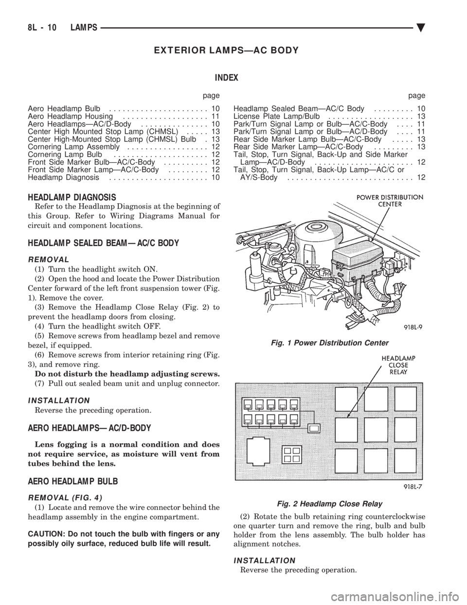
(2) Open the hood and locate the Power Distribution
Center forward of the left front suspension tower (Fig.
1). Remove the cover. (3) Remove the Headlamp Close Relay (Fig. 2) to
prevent the headlamp doors from closing. (4) Turn the headlight switch OFF.
(5) Remove screws from headlamp bezel and remove
bezel, if equipped. (6) Remove screws from interior retaining ring (Fig.
3), and remove ring. Do not disturb the headlamp adjusting screws.
(7) Pull out sealed beam unit and unplug connector.
INSTALLATION
Reverse the preceding operation.
AERO HEADLAMPSÐAC/D-BODY
Lens fogging is a normal condition and does
not require service, as moisture will vent from
tubes behind the lens.
AERO HEADLAMP BULB
REMOVAL (FIG. 4)
(1) Locate and remove the wire connector behind the
headlamp assembly in the engine compartment.
CAUTION: Do not touch the bulb with fingers or any
possibly oily surface, reduced bulb life will result. (2) Rotate the bulb retaining ring counterclockwise
one quarter turn and remove the ring, bulb and bulb
holder from the lens assembly. The bulb holder has
alignment notches.
INSTALLATION
Reverse the preceding operation.
Fig. 1 Power Distribution Center
Fig. 2 Headlamp Close Relay
8L - 10 LAMPS Ä
Page 664 of 2438
EXTERIOR LAMPSÐAY-BODY INDEX
page page
Center High Mounted Stop Lamp ............ 24
Center High Mounted Stop Lamp Bulb (CHMSL) . 24
Cornering Lamp or BulbÐAY/C-P-Body ........ 24
Front Side Marker BulbÐAY/C-P-Body ........ 23
Front Side Marker LampÐAY/C-P-Body ....... 23
General Information ....................... 22
Headlamp Diagnosis ...................... 22 Headlamps
............................. 22
License Plate Lamp or BulbÐAY/C-P-Body ..... 24
Park, Turn Signal Lamp or BulbÐAY/C-P-Body . . 22
Sealed Beam ........................... 22
Tail, Stop, Turn Signal, Side Marker and Back-Up Lamp or BulbÐAY/C-P-Body .............. 24
GENERAL INFORMATION
To service exterior lamps on AY/C-S-Body, refer to
procedures covered in Exterior LampsÐAC-Body sec-
tion. AC/C-S-Body uses the same lamps as AY/C-S-
Body.
HEADLAMPS
Conventional and halogen sealed beams are inter-
changeable, It is not recommended that they be
mixed. The lens, filament and reflector of sealed
beams are molded into one unit.
HEADLAMP DIAGNOSIS
For headlamp diagnosis, refer to the headlamp di-
agnosis chart at the beginning of this Group. Refer to
Wiring Diagrams manual for circuit and component
locations.
SEALED BEAM
REMOVAL
(1) Turn the headlight switch ON.
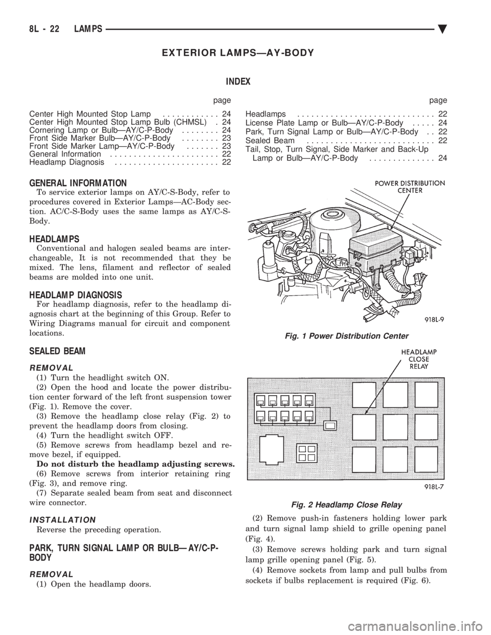
(2) Open the hood and locate the power distribu-
tion center forward of the left front suspension tower
(Fig. 1). Remove the cover. (3) Remove the headlamp close relay (Fig. 2) to
prevent the headlamp doors from closing. (4) Turn the headlight switch OFF.
(5) Remove screws from headlamp bezel and re-
move bezel, if equipped. Do not disturb the headlamp adjusting screws.
(6) Remove screws from interior retaining ring
(Fig. 3), and remove ring. (7) Separate sealed beam from seat and disconnect
wire connector.
INSTALLATION
Reverse the preceding operation.
PARK, TURN SIGNAL LAMP OR BULBÐAY/C-P-
BODY
REMOVAL
(1) Open the headlamp doors. (2) Remove push-in fasteners holding lower park
and turn signal lamp shield to grille opening panel
(Fig. 4). (3) Remove screws holding park and turn signal
lamp grille opening panel (Fig. 5). (4) Remove sockets from lamp and pull bulbs from
sockets if bulbs replacement is required (Fig. 6).
Fig. 1 Power Distribution Center
Fig. 2 Headlamp Close Relay
8L - 22 LAMPS Ä
Page 671 of 2438

PROBLEM
Headlamp door or doors fit poorly, rattle, or bang
when coming open or closed.
CHECK:
² Headlamp door fascia mounting bracket or adjust-
able stops for improper alignment.
² Headlamp door pivot brackets or door/crank lateral
adjustment for improperly aligned collar.
² For missing or worn pivot bushings.
² For defective motor.
HEADLAMP DOORÐAC-BODY
REMOVAL (FIG. 2)
(1) Remove the grill. Refer to Group 23, Body.
(2) Remove the front bumper assembly. Refer to
Group 23, Body. (3) Loosen and separate the grille opening panel
from the front fender on the side of the vehicle af-
fected. Refer to Group 23, Body. (4) Compress torsion bar retainer clip tabs to-
gether and slide the retainer toward the center of the
vehicle. Separate the torsion bar from the door crank
on the side of the vehicle affected. (5) Remove headlamp door side trim covers and
lower trim covers. (6) Remove outer pivot screw, door crank screw,
and loosen the door (lateral) adjustment collar. (7) Remove the door crank from the door and ad-
justment collar. (8) Lower the door from under the grille opening
panel and remove the door from the vehicle.
INSTALLATION
Reverse the preceding operation.
CONCEALED HEADLAMP MOTORÐAC-BODY
REMOVAL (FIG. 2)
(l) Remove the grille. Refer to Group 23, Body.
(2) Compress torsion bar retainers and slide them
toward the center of the vehicle. Separate the torsion
bar from the door cranks. (3) Disconnect the headlamp door drive motor wire
connector. Remove three motor attaching bolts and
separate the drive motor and torsion bar from the ve-
hicle.
INSTALLATION
Reverse the preceding operation.
HEADLAMP DOORÐAY BODY
REMOVAL
(1) Turn headlight switch ON.
Fig. 2 Concealed headlampsÐAC-body
Ä LAMPS 8L - 29
Page 672 of 2438

(2) Open hood and locate Power Distribution Cen-
ter forward of the left suspension tower (Fig. 3). (3) Remove cover from the center and pull the
Headlamp Close Relay (Fig. 4) to keep the headlamp
doors from closing. (4) Turn headlight switch OFF.
(5) Remove two grill mounting screws and remove
grill assembly (Fig. 5). (6) Spring tension must be relieved from the head-
lamp doors before removing headlamp motor torsion
bar clips. Locate the thumb wheel on bottom of head-
lamp motor (Fig. 6). Rotate thumb wheel approxi-
mately six to seven turns clockwise to relieve all
tension. (7) Remove torsion bar anchor clip (Fig. 7).
(8) Slide torsion bar sleeve over the torsion bar
(Fig. 8). (9) Remove three clips retaining turn signal lamp
shield to body (Fig. 9), and remove shield. (10) Remove two screws retaining headlamp cover
to headlamp cover bracket (Fig. 10). (11) Remove outer headlamp.
(12) Remove outer pivot screw (Fig. 11).
(13) Remove E-clip and door crank screw (Fig. 12).
(14) Remove three bolts retaining cam pivot to
body and remove cam pivot (Fig. 11). (15) Remove Headlamp door assembly.
INSTALLATION
Reverse the preceding operation. Before installing
torsion bar clips, the holes in the torsion bars, tor-
sion bar sleeves and headlamp door cam pivots must
be in alignment. Refer to Aligning Headlamp Doors.
HEADLAMP DRIVE MOTORÐAY BODY
REMOVAL
(1) Open headlamp doors. Refer to Headlamp Door
paragraph for instructions. (2) Remove grill mounting screws and remove grill
assembly (Fig. 5). (3) Spring tension must be relieved from headlamp
doors before removing the headlamp motor torsion
bar clips. Locate the thumb wheel on bottom of the
headlamp motor (Fig. 6). Rotate thumb wheel ap-
proximately six to seven turns (clockwise) to relieve
all tension. (4) Remove both torsion bar anchor clips (Fig. 7).
(5) Slide torsion bar sleeves over the torsion bar
(Fig. 8).
Fig. 3 Power Distribution Center
Fig. 4 Headlamp Close Relay
Fig. 5 Grill
Fig. 6 Headlamp MotorÐBottom View
8L - 30 LAMPS Ä