Page 2366 of 2438
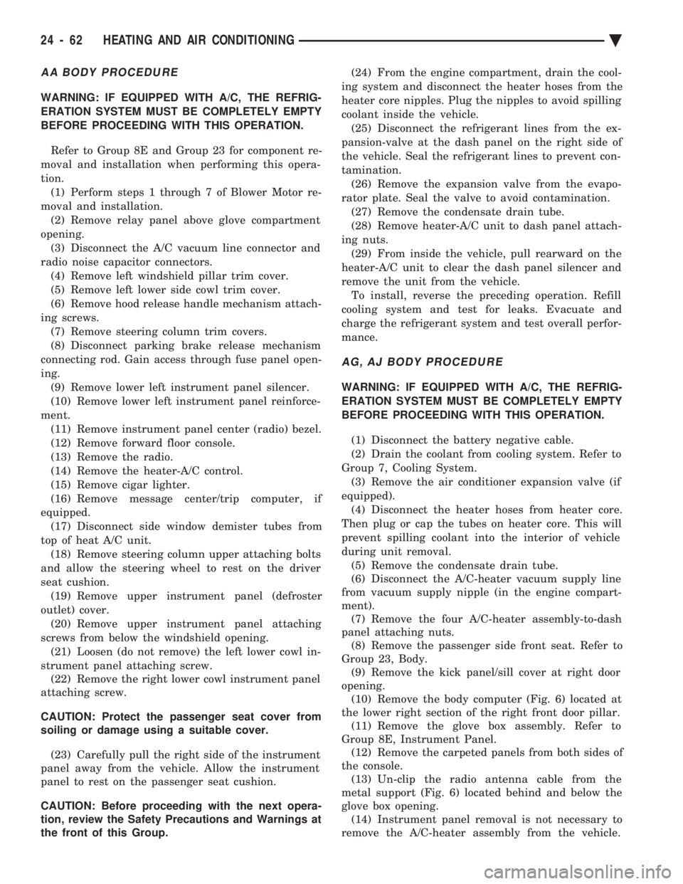
AA BODY PROCEDURE
WARNING: IF EQUIPPED WITH A/C, THE REFRIG-
ERATION SYSTEM MUST BE COMPLETELY EMPTY
BEFORE PROCEEDING WITH THIS OPERATION. Refer to Group 8E and Group 23 for component re-
moval and installation when performing this opera-
tion. (1) Perform steps 1 through 7 of Blower Motor re-
moval and installation. (2) Remove relay panel above glove compartment
opening. (3) Disconnect the A/C vacuum line connector and
radio noise capacitor connectors. (4) Remove left windshield pillar trim cover.
(5) Remove left lower side cowl trim cover.
(6) Remove hood release handle mechanism attach-
ing screws. (7) Remove steering column trim covers.
(8) Disconnect parking brake release mechanism
connecting rod. Gain access through fuse panel open-
ing. (9) Remove lower left instrument panel silencer.
(10) Remove lower left instrument panel reinforce-
ment. (11) Remove instrument panel center (radio) bezel.
(12) Remove forward floor console.
(13) Remove the radio.
(14) Remove the heater-A/C control.
(15) Remove cigar lighter.
(16) Remove message center/trip computer, if
equipped. (17) Disconnect side window demister tubes from
top of heat A/C unit. (18) Remove steering column upper attaching bolts
and allow the steering wheel to rest on the driver
seat cushion. (19) Remove upper instrument panel (defroster
outlet) cover. (20) Remove upper instrument panel attaching
screws from below the windshield opening. (21) Loosen (do not remove) the left lower cowl in-
strument panel attaching screw. (22) Remove the right lower cowl instrument panel
attaching screw.
CAUTION: Protect the passenger seat cover from
soiling or damage using a suitable cover.
(23) Carefully pull the right side of the instrument
panel away from the vehicle. Allow the instrument
panel to rest on the passenger seat cushion.
CAUTION: Before proceeding with the next opera-
tion, review the Safety Precautions and Warnings at
the front of this Group. (24) From the engine compartment, drain the cool-
ing system and disconnect the heater hoses from the
heater core nipples. Plug the nipples to avoid spilling
coolant inside the vehicle. (25) Disconnect the refrigerant lines from the ex-
pansion-valve at the dash panel on the right side of
the vehicle. Seal the refrigerant lines to prevent con-
tamination. (26) Remove the expansion valve from the evapo-
rator plate. Seal the valve to avoid contamination. (27) Remove the condensate drain tube.
(28) Remove heater-A/C unit to dash panel attach-
ing nuts. (29) From inside the vehicle, pull rearward on the
heater-A/C unit to clear the dash panel silencer and
remove the unit from the vehicle. To install, reverse the preceding operation. Refill
cooling system and test for leaks. Evacuate and
charge the refrigerant system and test overall perfor-
mance.
AG, AJ BODY PROCEDURE
WARNING: IF EQUIPPED WITH A/C, THE REFRIG-
ERATION SYSTEM MUST BE COMPLETELY EMPTY
BEFORE PROCEEDING WITH THIS OPERATION.
(1) Disconnect the battery negative cable.
(2) Drain the coolant from cooling system. Refer to
Group 7, Cooling System. (3) Remove the air conditioner expansion valve (if
equipped). (4) Disconnect the heater hoses from heater core.
Then plug or cap the tubes on heater core. This will
prevent spilling coolant into the interior of vehicle
during unit removal. (5) Remove the condensate drain tube.
(6) Disconnect the A/C-heater vacuum supply line
from vacuum supply nipple (in the engine compart-
ment). (7) Remove the four A/C-heater assembly-to-dash
panel attaching nuts. (8) Remove the passenger side front seat. Refer to
Group 23, Body. (9) Remove the kick panel/sill cover at right door
opening. (10) Remove the body computer (Fig. 6) located at
the lower right section of the right front door pillar. (11) Remove the glove box assembly. Refer to
Group 8E, Instrument Panel. (12) Remove the carpeted panels from both sides of
the console. (13) Un-clip the radio antenna cable from the
metal support (Fig. 6) located behind and below the
glove box opening. (14) Instrument panel removal is not necessary to
remove the A/C-heater assembly from the vehicle.
24 - 62 HEATING AND AIR CONDITIONING Ä
Page 2429 of 2438
Page 1
03/30/99
Rev. 0
7DEOH�2I�&RQWHQWV
Section Page
1.0 Viewing A Manual In Windows98/95/NT
…………………………………. 2
2.0 Viewing A Manual In Windows 3.1 ……………………………………………. 3
3.0 Using The CD-ROM
3.1 Welcome Page Of A Manual ……………………………………………………… 4
3.2 Tab Page Of A Manual ……………………………………………………………. 5 3.3 Returning To The Tab Page Of A Manual ……………………………………… 6
3.4 Viewing The Contents Of A Group W ithin A Manual ………………………….. 7
3.5 Using Electronic Bookmarks To Navigate A Manual ………………………….. 8
4.0 Using The Acrobat Reader Toolbar
4.1 Acrobat Reader On-Line Help …………………………………………………… 9
4.2 Summary Of Acrobat Reader Toolbar Features ………………………………. 10
Page 2430 of 2438
2
1.0 Viewing A Manual In Windows98/95/NT
To view the contents of A CD-ROM, you will need to keep the CD-ROM in
the CD-ROM drive. The Acrobat Reader runs off the hard drive and
uses the CD-ROM drive to access the document content.
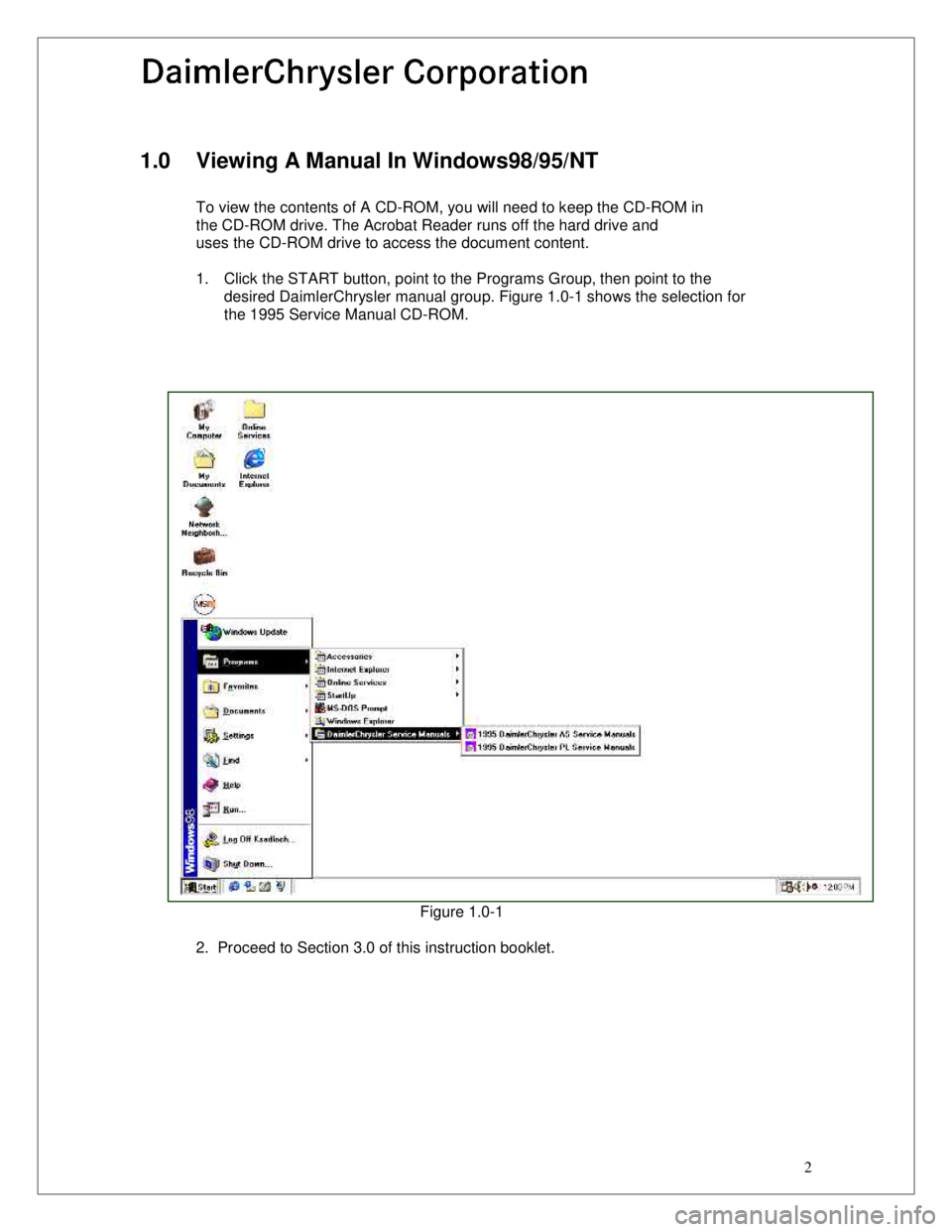
1. Click the START button, point to the Programs Group, then point to the desired DaimlerChrysler manual group. Figure 1.0-1 shows the selection for
the 1995 Service Manual CD-ROM.
Figure 1.0-1
2. Proceed to Section 3.0 of this instruction booklet.
Page 2431 of 2438
Page 3
03/30/99
Rev. 0
2.0 Viewing A Service Manual In Windows3.1
To view the contents of A CD-ROM, you will need to keep the CD-ROM in
the CD-ROM drive. The Acrobat Reader runs off the hard drive and
uses the CD-ROM drive to access the document content.
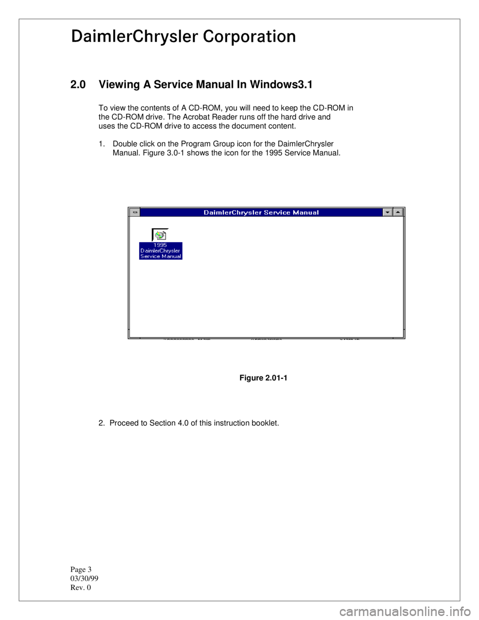
1. Double click on the Program Group icon for the DaimlerChrysler Manual. Figure 3.0-1 shows the icon for the 1995 Service Manual.
Figure 2.01-1
2. Proceed to Section 4.0 of this instruction booklet.
Page 2435 of 2438
Page 7
03/30/99
Rev. 0
3.4 Viewing The Contents Of A Group Within A Manual
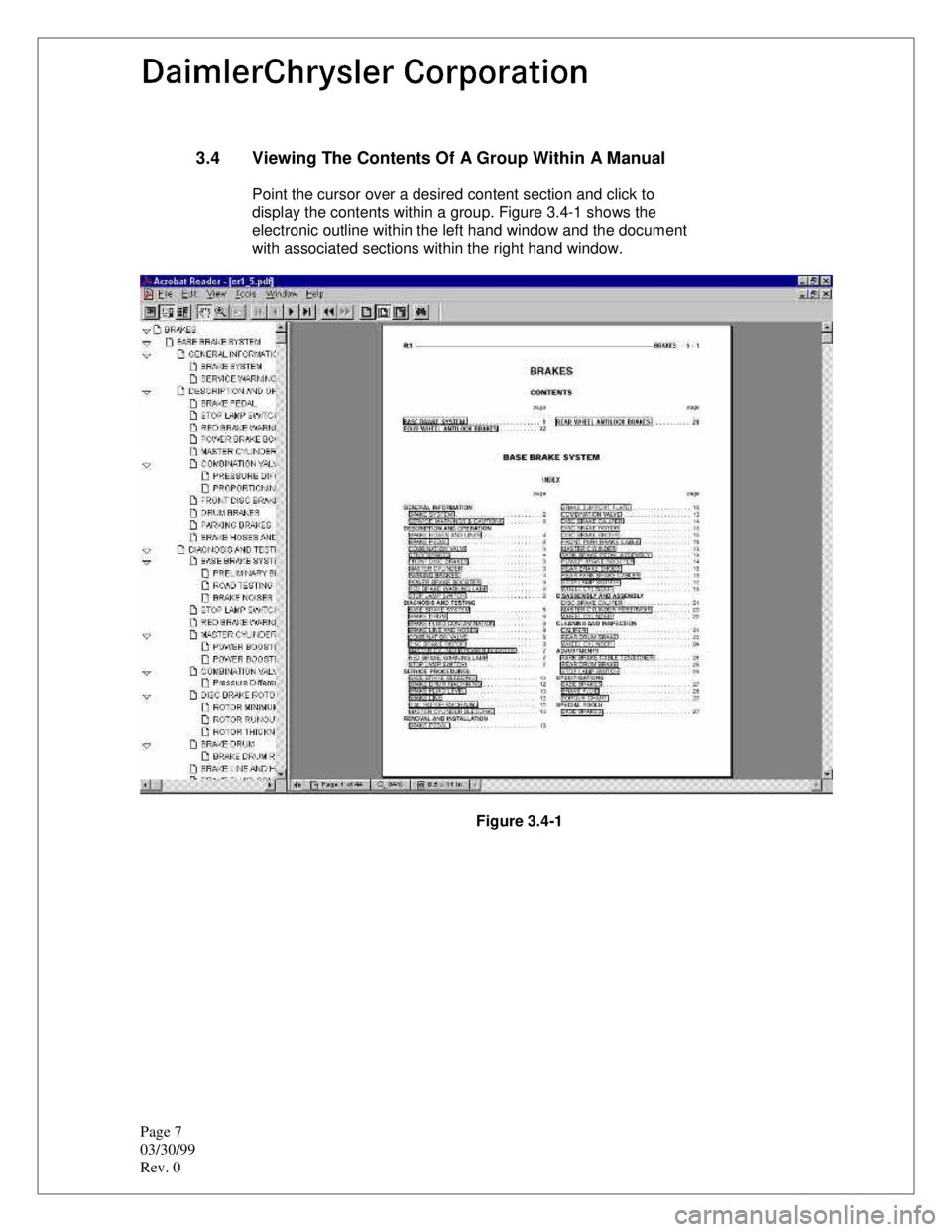
Point the cursor over a desired content section and click to
display the contents within a group. Figure 3.4-1 shows the
electronic outline within the left hand window and the document
with associated sections within the right hand window.
Figure 3.4-1
Page 2436 of 2438
8
3.5 Using Electronic Bookmarks For Navigation Within A Manual.
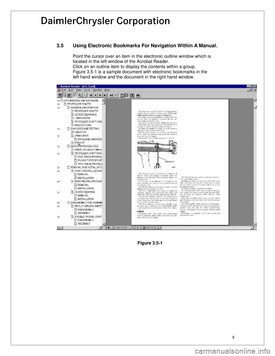
Point the cursor over an item in the electronic outline window which is located in the left window of the Acrobat Reader.
Click on an outline item to display the contents within a group.
Figure 3.5-1 is a sample document with electronic bookmarks in the
left hand window and the document in the right hand window.
Figure 3.5-1
Page 2437 of 2438
Page 9
03/30/99
Rev. 0
4.0 Using The Acrobat Reader
4.1 Acrobat Reader On-Line Help
The complete user help file can be accessed by selecting the
Help Menu option and then Reader Online Guide option within
the Acrobat Reader application.
4.2 Summary Of Acrobat Reader Toolbar Features
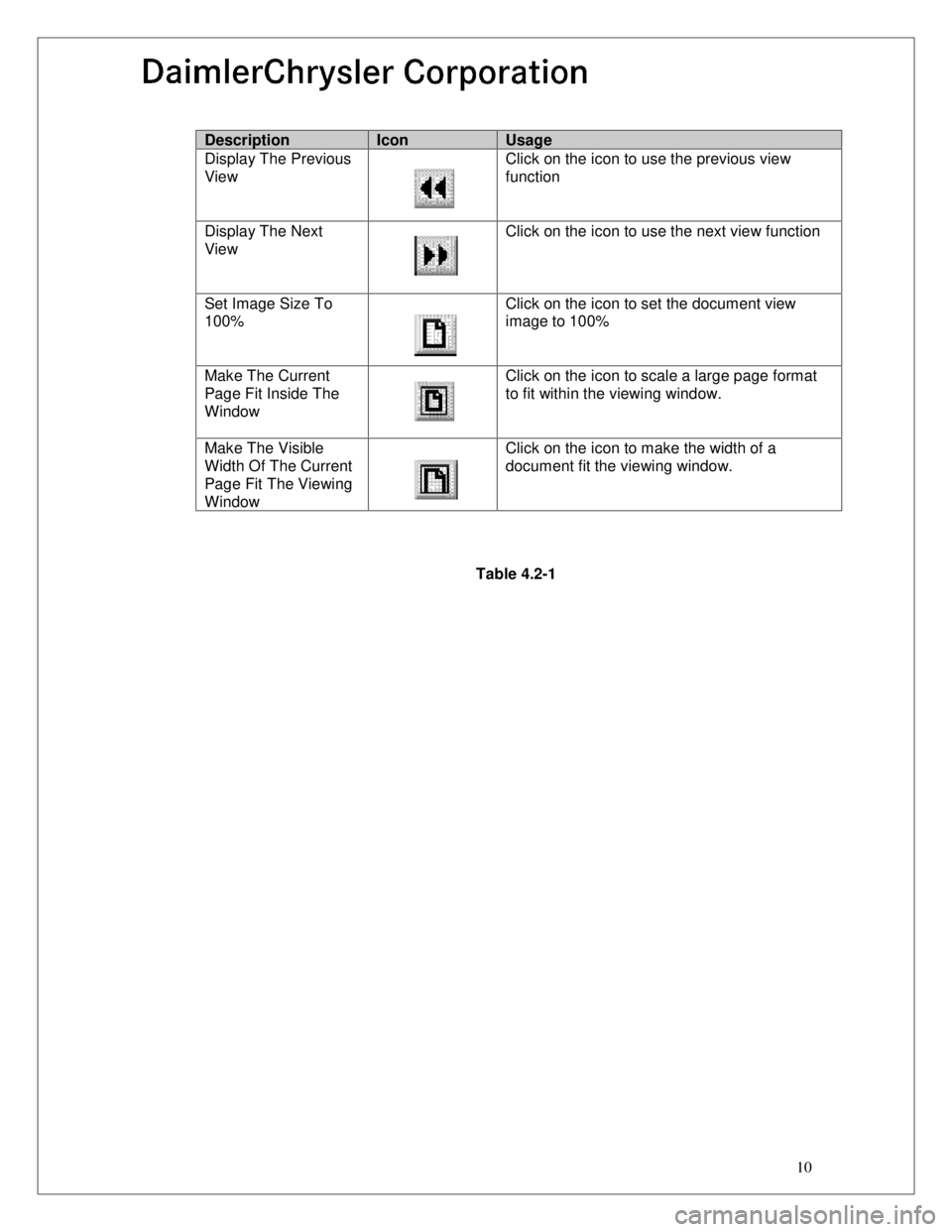
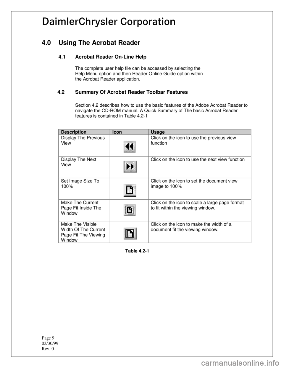
Section 4.2 describes how to use the basic features of the Adobe Acrobat Reader to
navigate the CD-ROM manual. A Quick Summary of The basic Acrobat Reader
features is contained in Table 4.2-1
DescriptionIconUsage
Display The Previous
View Click on the icon to use the previous view
function
Display The Next
View Click on the icon to use the next view function
Set Image Size To
100% Click on the icon to set the document view
image to 100%
Make The Current
Page Fit Inside The
Window Click on the icon to scale a large page format
to fit within the viewing window.
Make The Visible
Width Of The Current
Page Fit The Viewing
Window Click on the icon to make the width of a
document fit the viewing window.
Table 4.2-1
Page 2438 of 2438
10
DescriptionIconUsage
Display The Previous
View Click on the icon to use the previous view
function
Display The Next
View Click on the icon to use the next view function
Set Image Size To
100% Click on the icon to set the document view
image to 100%
Make The Current
Page Fit Inside The
Window Click on the icon to scale a large page format
to fit within the viewing window.
Make The Visible
Width Of The Current
Page Fit The Viewing
Window Click on the icon to make the width of a
document fit the viewing window.
Table 4.2-1