1993 CHEVROLET PLYMOUTH ACCLAIM window
[x] Cancel search: windowPage 514 of 2438
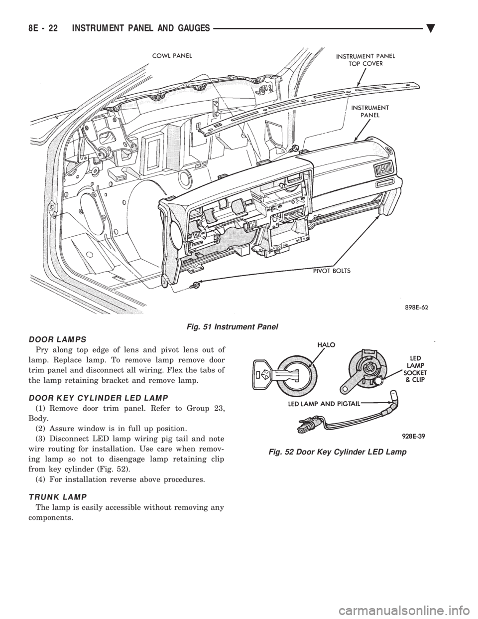
DOOR LAMPS
Pry along top edge of lens and pivot lens out of
lamp. Replace lamp. To remove lamp remove door
trim panel and disconnect all wiring. Flex the tabs of
the lamp retaining bracket and remove lamp.
DOOR KEY CYLINDER LED LAMP
(1) Remove door trim panel. Refer to Group 23,
Body. (2) Assure window is in full up position.
(3) Disconnect LED lamp wiring pig tail and note
wire routing for installation. Use care when remov-
ing lamp so not to disengage lamp retaining clip
from key cylinder (Fig. 52). (4) For installation reverse above procedures.
TRUNK LAMP
The lamp is easily accessible without removing any
components.
Fig. 51 Instrument Panel
Fig. 52 Door Key Cylinder LED Lamp
8E - 22 INSTRUMENT PANEL AND GAUGES Ä
Page 519 of 2438

(3) Remove lower steering column cover (Fig. 10
through 14).
(4) Place gear shift lever in neutral or park.
(5) Remove guide tube from behind fuse block and
disconnect cable eyelet from column actuating arm. (6) Release lock bar on column insert, squeeze legs
together and remove from column (Fig. 13). (7) Secure insert and cable guide out of the way.
(8) Remove the rear window defogger bezel and ra-
dio bezel. (9) Remove the upper steering column cover.
(10) Remove the four screws attaching cluster
housing to the base panel (Fig. 15). (11) Pull cluster rearward, reach behind cluster
and disconnect the two wiring harnesses. (12) Remove cluster assembly. INSTALLATION
(1) Connect wiring harnesses.
(2) Install cluster assembly while routing trans-
mission range indicator guide tube through access
hole in base panel (Fig. 10 through 14). Release
guide tube from behind fuse block. (3) Insert flange of column insert into column,
squeeze legs together with tabs under column jacket
and engage lock bar to secure insert (Fig. 13). (4) Hook cable eyelet to steering column actuator
check pointer, should indicate neutral. Do not kink
Fig. 10 Transmission Range Indicator
Fig. 11 Transmission Range Indicator Step 1
Fig. 12 Transmission Range Indicator Step 2
Fig. 13 Transmission Range Indicator Step 3
Ä INSTRUMENT PANEL AND GAUGES 8E - 27
Page 520 of 2438
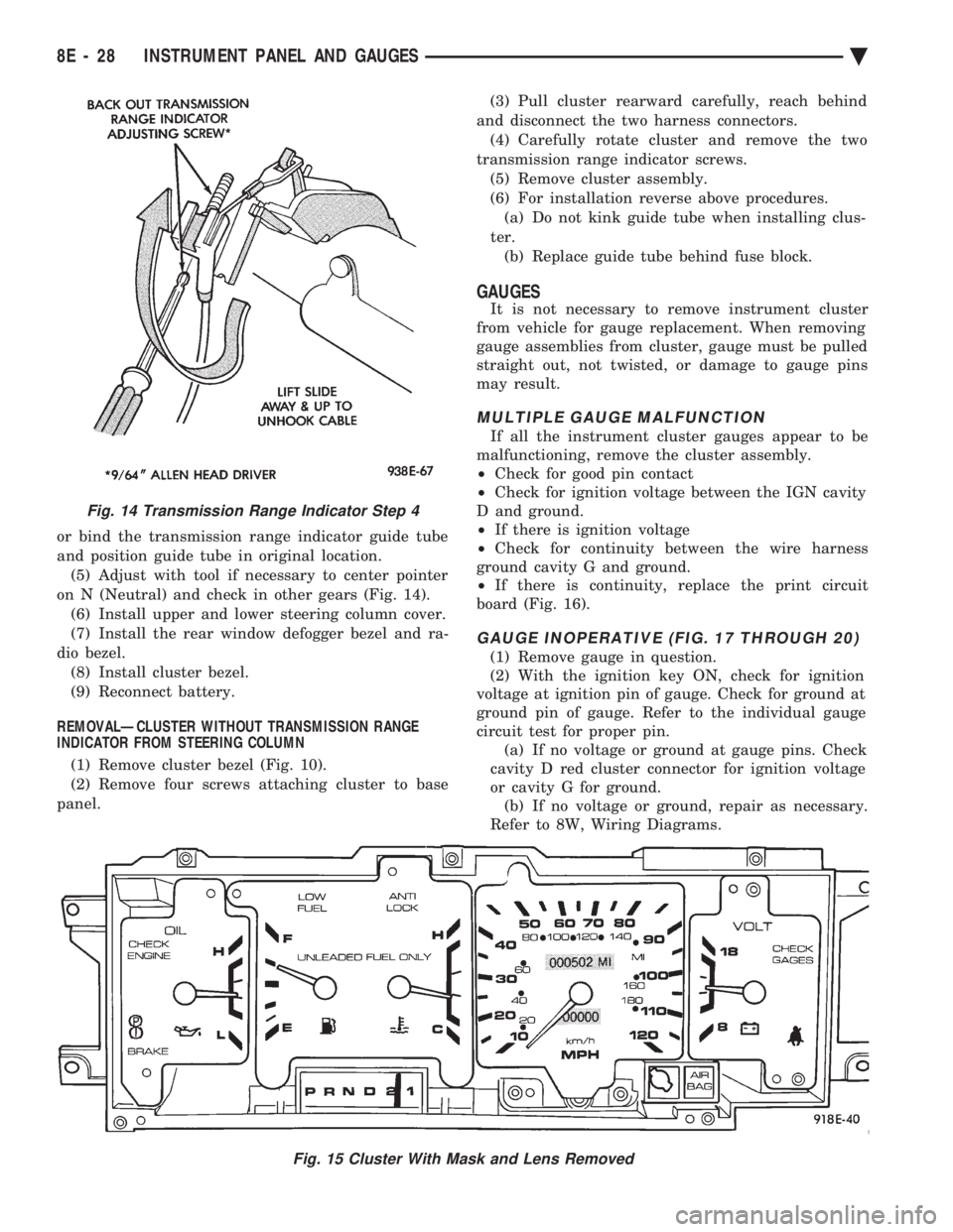
or bind the transmission range indicator guide tube
and position guide tube in original location.(5) Adjust with tool if necessary to center pointer
on N (Neutral) and check in other gears (Fig. 14). (6) Install upper and lower steering column cover.
(7) Install the rear window defogger bezel and ra-
dio bezel. (8) Install cluster bezel.
(9) Reconnect battery.
REMOVALÐCLUSTER WITHOUT TRANSMISSION RANGE
INDICATOR FROM STEERING COLUMN
(1) Remove cluster bezel (Fig. 10).
(2) Remove four screws attaching cluster to base
panel. (3) Pull cluster rearward carefully, reach behind
and disconnect the two harness connectors. (4) Carefully rotate cluster and remove the two
transmission range indicator screws. (5) Remove cluster assembly.
(6) For installation reverse above procedures. (a) Do not kink guide tube when installing clus-
ter. (b) Replace guide tube behind fuse block.
GAUGES
It is not necessary to remove instrument cluster
from vehicle for gauge replacement. When removing
gauge assemblies from cluster, gauge must be pulled
straight out, not twisted, or damage to gauge pins
may result.
MULTIPLE GAUGE MALFUNCTION
If all the instrument cluster gauges appear to be
malfunctioning, remove the cluster assembly.
² Check for good pin contact
² Check for ignition voltage between the IGN cavity
D and ground.
² If there is ignition voltage
² Check for continuity between the wire harness
ground cavity G and ground.
² If there is continuity, replace the print circuit
board (Fig. 16).
GAUGE INOPERATIVE (FIG. 17 THROUGH 20)
(1) Remove gauge in question.
(2) With the ignition key ON, check for ignition
voltage at ignition pin of gauge. Check for ground at
ground pin of gauge. Refer to the individual gauge
circuit test for proper pin. (a) If no voltage or ground at gauge pins. Check
cavity D red cluster connector for ignition voltage
or cavity G for ground. (b) If no voltage or ground, repair as necessary.
Refer to 8W, Wiring Diagrams.
Fig. 15 Cluster With Mask and Lens Removed
Fig. 14 Transmission Range Indicator Step 4
8E - 28 INSTRUMENT PANEL AND GAUGES Ä
Page 531 of 2438

(3) Remove switch assembly and escutcheon from
switch module by removing four attaching screws
(Fig. 37).
(4) Remove headlamp switch mounting plate from
switch by removing retaining nut. (5) For installation reverse above procedures.
REAR WINDOW DEFOGGER SWITCHREPLACEMENT
(1) Remove headlamp and accessory switch module
from instrument panel (Fig. 36). (2) Remove rear window defogger switch by de-
pressing snap-in clips on top and bottom of switch. (3) For installation reverse above procedures.
HOOD RELEASE HANDLE AND CABLEREPLACEMENT
(1) Disconnect hood release cable at hood latch.
(2) Remove two screws from underside of hood re-
lease handle. (3) Pull mechanism assembly rearward to remove.
(4) For installation reverse above procedures.
PARK BRAKE RELEASE HANDLE AND LINK REPLACEMENT
(1) Remove left side under panel silencer.
(2) Remove park brake link from lever on park
brake mechanism. (3) Remove upper and lower cluster bezels.
(4) Pull park brake release handle and remove
screw. (5) Remove column cover/park brake release han-
dle assembly by removing four remaining screws. (6) For installation reverse above procedures.
LAMP OUTAGE MODULE REPLACEMENT
(1) Disconnect battery negative cable and isolate
or remove fuse #13 prior to removing switch or wires
may short to ground. (2) Remove lower right instrument panel silencer.
(3) Remove glove box and ash receiver module.
(4) Remove three screws attaching the mounting
bracket to instrument panel. (5) Lower bracket and module assembly, to discon-
nect wire connectors. (6) Remove two screws attaching the Lamp Outage
Module to bracket. (7) Remove two screws attaching the security mod-
ule to bracket. (8) To installation reverse above procedures.
BODY CONTROLLER REPLACEMENT
(1) Remove right side door sill and kick panel trim
five screws (Fig. 38).
(2) Disconnect body controller wiring.
(3) Remove controller retaining nuts.
(4) For installation reverse above procedures.
GLOVE BOX/ASH RECEIVER ASSEMBLY REPLACEMENT
(1) Disconnect battery negative cable and isolate
or remove fuse #13 prior to removing switch or wires
may short to ground. (2) Remove center support cover/floor console as
necessary. (3) Disconnect glovebox/Ash receiver wiring con-
nectors (Fig. 39). (4) Remove ten screws around edge of glovebox/ash
receiver assembly. (5) Remove glovebox/ash receiver module from in-
strument panel. (6) For installation reverse above procedures.
Fig. 37 Headlamp and Accessory Switch
Fig. 38 Body Controller Location
Ä INSTRUMENT PANEL AND GAUGES 8E - 39
Page 549 of 2438
(11) Remove two screws from fuse block and lower
fuse block. (12) Remove three screws from hood release and
lower hood release handle. (13) Remove flasher relay from bracket on center
distribution duct. (14) Remove screw from ATC sensor motor assem-
bly and unhook from bracket if equipped. (15) Remove the radio ground screw above flasher
relay mount. (16) Remove center distribution duct screw from
left instrument panel lower brace, then remove four
screws to remove left lower brace.
(17) Remove five nuts on steering column and drop
column, then remove two upper column attaching studs.
(18) Remove two screws and pull out compact disc
player or cubby box, disconnect Co-Axial cable from
compact disc player. (19) Remove Electronic Vehicle Information Center
(E.V.I.C.) or Traveler from vehicle. (20) Remove radio.
(21) Remove A.T.C., A/C or heater controls. (22) Squeeze latches on side of Rear Window defog-
ger switch and remove. (23) Snap off cluster lower trim bezel, switch pod
vent grille, speaker grilles and defroster grilles. (24) Remove switch pod assembly.
(25) Remove cluster assembly.
(26) Remove dash speakers.
(27) Snap out bezel with or without message center
and disconnect wiring. (28) Open glovebox door, squeeze sides and roll
glovebox completely open. Remove glovebox light
switch, and disconnect wires. (29) Loosen right cowl side pivot bolt through
glovebox opening then close glovebox. (30) Loosen left cowl side pivot.
(31) Remove four screw attachments at top of in-
strument panel and roll panel out. (32) Pull wiring, antenna cable, A/C cable and vac-
uum lines out of instrument panel. Disconnect demis-
ter hose and remove instrument panel with ducts
attached. (33) Transfer ducts and brackets onto new panel.
(34) For instrument panel roll up, reverse
above procedures.
INTERIOR LAMP REMOVAL
The Dome, Floor Console and Door Lamps operate
when the doors are open or headlamp switch is
placed in courtesy position.
DOME LAMP
(1) Pry either the forward or rearward edge of the
dome lamp to free it from retaining bracket. (2) Pry either the forward or rearward edge of the
lens away from the bezel and replace lamp. (3) For installation reverse above procedures.
FRONT HEADER READING LAMP
Pull lamp from headliner. Disconnect wiring and
replace lamp.
FLOOR CONSOLE LAMP
Pry along top edge of lamp and pivot lamp out of
floor console, the lens does not remove. Remove lamp
and twist out lamp socket. Replace lamp.
DOOR LAMPS
Pry along bottom edge of lamp and pivot lamp out
of door trim panel, the lens does not remove. Remove
lamp and twist out lamp socket. Replace lamp.
DOOR REFLECTORS
Pry reflector away from the door trim panel, and
replace.
TRUNK LAMP
Remove lens by prying lens out of trunk trim panel
and replace bulb.
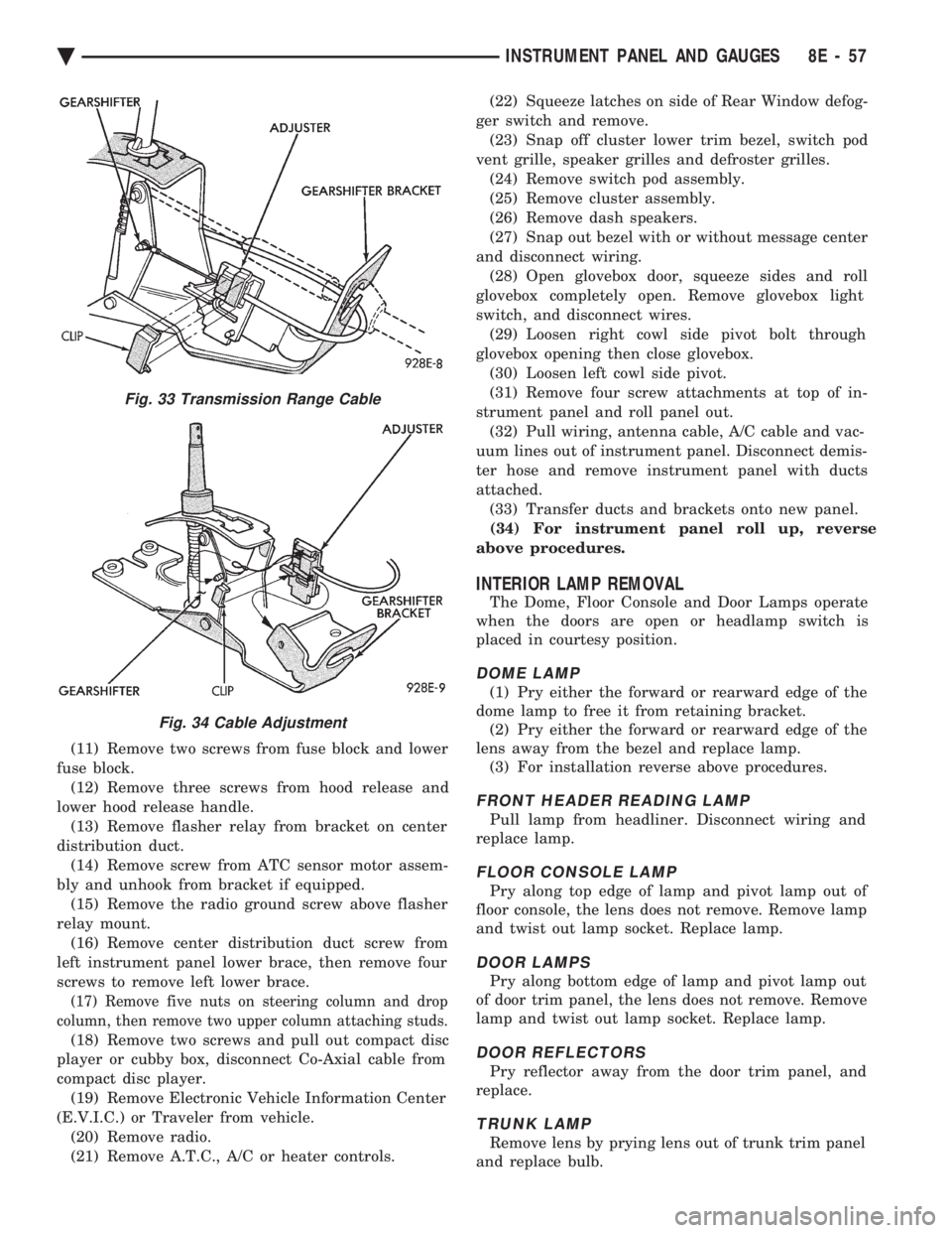
Fig. 33 Transmission Range Cable
Fig. 34 Cable Adjustment
Ä INSTRUMENT PANEL AND GAUGES 8E - 57
Page 562 of 2438

CIGAR LIGHTER REPLACEMENT
(1) Remove center bezel assembly (Fig. 23).
(2) Remove center module lower cover or open for-
ward console lid. (3) Unscrew lighter receptacle shell from recepta-
cle and remove from base instrument panel. (4) Disconnect wiring connectors from lighter re-
ceptacle and remove from vehicle. (5) For installation reverse above procedures.
REAR WINDOW DEFOGGER AND/OR FOG LAMP SWITCH REPLACEMENT
(1) Remove center module bezel assembly (Fig. 20).
(2) Remove two switch bezel screws (Fig. 24).
(3) Pull switches and bezel rearward and discon-
nect wiring connector. (4) Remove two switch retaining screws.
(5) Remove switch from bezel.
(6) For installation reverse above procedures.
INTERMITTENT WIPE MODULE REPLACEMENT
(1) Remove lower steering column cover.
(2) Slide intermittent wipe module off of bracket
located on steering column reinforcement (Fig. 25). (3) Disconnect wiring connector from module and
remove module from vehicle. (4) For installation reverse above procedures.
GLOVE BOX LAMP AND SWITCHREPLACEMENT
(1) Disconnect battery and/or pull fuse # 13 before
starting removal procedure. (2) Open glove box door (Fig. 26).
(3) Carefully pry lamp from its mounting surface
with tip of a small screwdriver. (4) Pull lamp from box and disconnect electrical
leads. (5) Remove lamp.
(6) For installation reverse above procedures.
CONSOLETTE ASSEMBLY REPLACEMENT
(1) Remove shifter handle.
(2) Unsnap transmission range indicator bezel or
shift boot bezel from consolette, disconnect wiring
and remove bezel assembly (Fig. 27). (3) Remove two screws from side of armrest.
(4) Remove four caps which cover attaching
screws. (5) Remove four attaching screws.
(6) Lift consolette up and over shift mechanism to
remove. (7) For installation reverse above procedures.
Fig. 24 Rear Window Defogger and Fog Lamp Switch
Fig. 25 Intermittent Wipe Module
Fig. 26 Glove Box Lamp and Switch
8E - 70 INSTRUMENT PANEL AND GAUGES Ä
Page 563 of 2438
CENTER CONSOLE ASSEMBLY REPLACEMENT
(1) Place transmission in neutral and remove
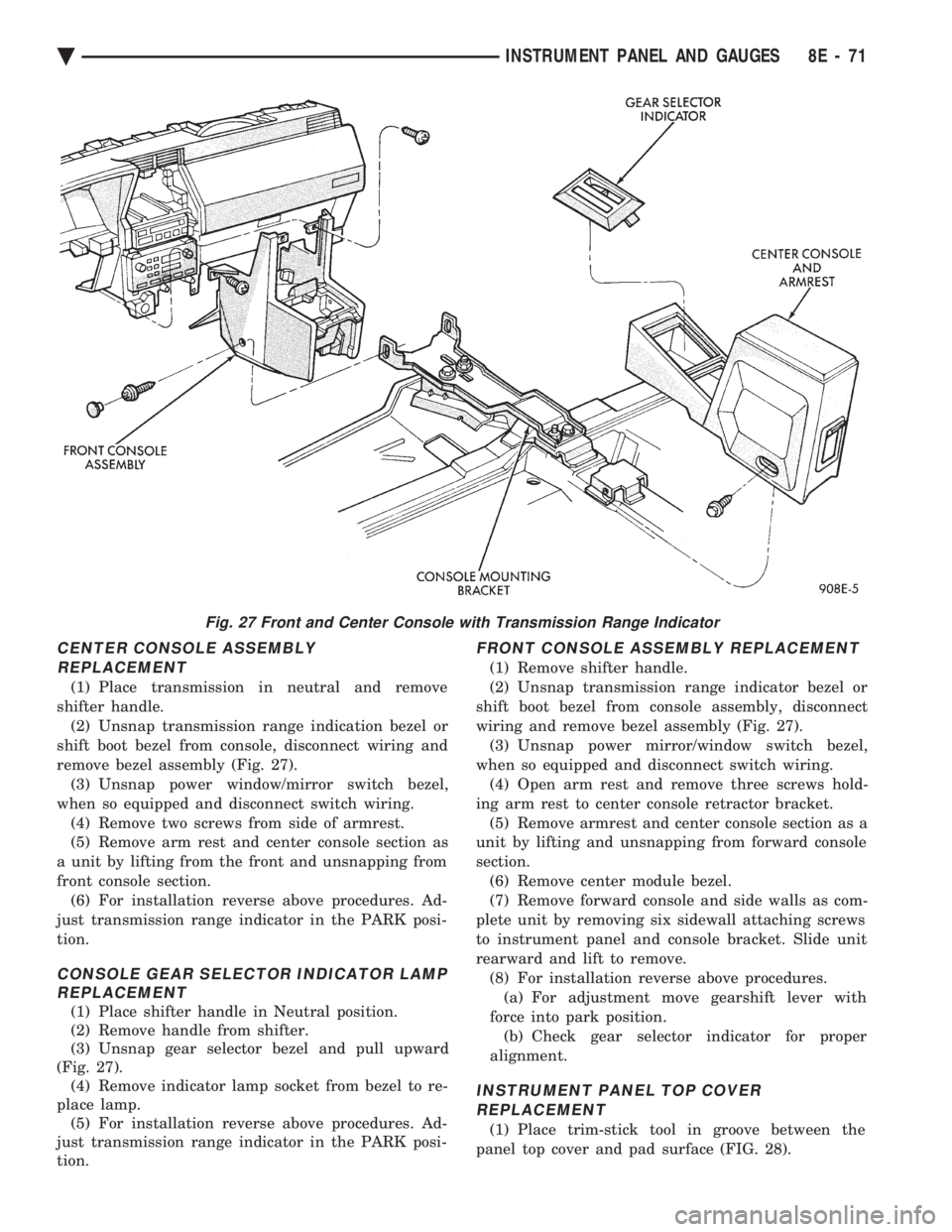
shifter handle. (2) Unsnap transmission range indication bezel or
shift boot bezel from console, disconnect wiring and
remove bezel assembly (Fig. 27). (3) Unsnap power window/mirror switch bezel,
when so equipped and disconnect switch wiring. (4) Remove two screws from side of armrest.
(5) Remove arm rest and center console section as
a unit by lifting from the front and unsnapping from
front console section. (6) For installation reverse above procedures. Ad-
just transmission range indicator in the PARK posi-
tion.
CONSOLE GEAR SELECTOR INDICATOR LAMP REPLACEMENT
(1) Place shifter handle in Neutral position.
(2) Remove handle from shifter.
(3) Unsnap gear selector bezel and pull upward
(Fig. 27). (4) Remove indicator lamp socket from bezel to re-
place lamp. (5) For installation reverse above procedures. Ad-
just transmission range indicator in the PARK posi-
tion.
FRONT CONSOLE ASSEMBLY REPLACEMENT
(1) Remove shifter handle.
(2) Unsnap transmission range indicator bezel or
shift boot bezel from console assembly, disconnect
wiring and remove bezel assembly (Fig. 27). (3) Unsnap power mirror/window switch bezel,
when so equipped and disconnect switch wiring. (4) Open arm rest and remove three screws hold-
ing arm rest to center console retractor bracket. (5) Remove armrest and center console section as a
unit by lifting and unsnapping from forward console
section. (6) Remove center module bezel.
(7) Remove forward console and side walls as com-
plete unit by removing six sidewall attaching screws
to instrument panel and console bracket. Slide unit
rearward and lift to remove. (8) For installation reverse above procedures.(a) For adjustment move gearshift lever with
force into park position. (b) Check gear selector indicator for proper
alignment.
INSTRUMENT PANEL TOP COVER REPLACEMENT
(1) Place trim-stick tool in groove between the
panel top cover and pad surface (FIG. 28).
Fig. 27 Front and Center Console with Transmission Range Indicator
Ä INSTRUMENT PANEL AND GAUGES 8E - 71
Page 590 of 2438

SPEAKERS INDEX
page page
AA Body ............................... 24
AC and AY Bodies ....................... 27
AC and AY Bodies ....................... 24
AG and AJ Bodies ....................... 25 AP Body
............................... 26
Infinity Remote Amplifier ................... 28
Relay/ChokeÐInfinity Speaker ............... 29
AA BODY
FRONT DOOR MOUNTED SPEAKER
REPLACEMENT
(1) Remove power window switch.
(2) Pry out on speaker grille at two locations on
forward edge of grille to disengage clips (Fig. 20).
(3) Remove two speaker mounting screws.
(4) Pull speaker away from door and disconnect
wiring connector. (5) For installation reverse the above procedures.
REAR DOOR MOUNTED SPEAKERREPLACEMENT
(1) Carefully pry with a blunt edge tool at the two
slotted openings on top edge of grille to disengage
clips. (2) Tilt top edge of grille away from door and lift
up to disengage plastic hooks on grille from trim
panel. (3) To aid in removing speaker it may be necessary
to disengage door trim panel near speaker opening. (4) Remove speaker-adaptor retaining screws (Fig.
21).
(5) Pull speaker away from door and disconnect
wiring connector. (6) For installation reverse above procedures.
AC and AY BODIES
INSTRUMENT PANEL SPEAKERSREPLACEMENT
(1) Carefully pry up at rearward corners of grille
with a blunt edge tool to disengage two plastic posts
from receptacle cavities in the instrument panel pad. (2) As rearward edge of grille comes free of pad in-
sert your fingers under exposed grille surface and
push up to disengage two more posts at forward cor-
ners of grille. (3) Remove two speaker attaching screws.
(4) Lift up speaker and disconnect wire connector.
Remove speaker. (5) For installation reverse above procedures.
FRONT DOOR SPEAKER REMOVAL
(1) Remove door trim panel, refer to Group 23,
Body.
Fig. 20 Front Door Mounted SpeakerÐAA Body
Fig. 21 Rear Door Mounted SpeakerÐAA Body
8F - 24 AUDIO SYSTEM Ä