1993 CHEVROLET PLYMOUTH ACCLAIM window
[x] Cancel search: windowPage 691 of 2438

REAR WINDOW DEFOGGER
CONTENTS
page page
CONTROL SWITCH/TIMER RELAY MODULE . . 1
GENERAL INFORMATION .................. 1REPAIR GRID LINES, TERMINALS AND PIGTAILS.3
SERVICE PROCEDURES ................... 1
GENERAL INFORMATION
For proper operation of the Rear Window Defogger
system refer to the Owner's Manual. Vehicles equipped with an electrically heated rear
window defogger also have a 40/90 amp generator. The system consists of a rear glass with two verti-
cal bus bars and a series of electrically connected
grid lines fired on the inside surface. A control
switch and a timer relay combined into a single as-
sembly is used on all models (Fig.1).
Circuit protection is provided by a fusible link, lo-
cated in the charging circuit, for the heated grid cir-
cuit and by a fuse for the relay control circuit. When the switch is turned to the ON position, cur-
rent is directed to the rear defogger grid lines. The
heated grid lines heat the rear glass to clear the sur-
face of fog or frost.
CAUTION: Grid lines can be damaged or scraped
off with sharp instruments, care should be taken in
cleaning glass or removing foreign materials, de-
cals or stickers. Normal glass cleaning solvents or
hot water used with rags or toweling is recom-
mended.
CONTROL SWITCH/TIMER RELAY MODULE
The control switch and timer relay are integrated
into a single panel or console mounted assembly. Ac-
tuating the switch energizes the circuit which allows
current to flow through the grid lines. Upon initial
actuation for approximately ten minutes, or until ei-
ther the switch or ignition is turned off. An indicat-
ing lamp illuminates a lens inlaid in the control
switch.
SERVICE PROCEDURES
Electrically heated rear window defogger operation
can be checked in vehicle in the following manner: (1) Turn ignition ON.
(2) Turn rear window defogger control switch ON.
(3) Using a ammeter on the battery. Turn the De-
fogger control switch ON, a distinct increase in am-
perage draw should be noted. (4) The rear window defogger operation can be
checked by feeling the glass. A distinct difference in
temperature between the grid lines and adjacent
clear glass can be detected in three to four minutes
of operation. (5) Using a DC voltmeter (Fig. 2) contact terminal
B with the negative lead, and terminal A with the
positive lead. The voltmeter should read 10-14 volts.
Fig. 1 Rear Window DefoggerÐTypical
Fig. 2 Rear Glass Grid Line TestÐTypical
Ä REAR WINDOW DEFOGGER 8N - 1
Page 692 of 2438

(6) Steps (3, 4 or 5) above will confirm system op-
eration. Indicator light illumination means that
there is power available at the output of the relay
only, and does not necessarily verify system opera-
tion. (7) If turning the switch ON produced no distinct
current draw on the ammeter the problem should be
isolated in the following manner: (a) Confirm the ignition switch is ON.
(b) Ensure that the heated rear glass feed wire is
connected to the terminal or pigtail and that the
ground wire is in fact grounded. (c) Ensure that the fusible link and control cir-
cuit fuse is operational and all electrical connec-
tions are secure.
(8) When the above steps have been completed and
the system is still inoperative, one or more of the fol-
lowing is defective: (a) Control switch/timer relay module.
(b) All rear window grid lines would have to be
broken or one of the feed wires are not connected
for the system to be inoperative.
(9) If turning the switch ON produces severe volt-
meter deflection, the circuit should be closely
checked for a shorting condition. (10) If the system operation has been verified but
indicator lamp does not light, replace the switch. (11) For detailed wiring information, refer to group
8W, Wiring Diagrams.
GRID TEST
The horizontal grid lines and vertical bus bar lines
printed and fired on inside surface of rear window
glass (Fig. 2) comprise an electrical parallel circuit.
The electrically conductive lines are composed of a
silver-ceramic material which when fired on glass be-
comes bonded to the glass and is highly resistant to
abrasion. It is possible, however, that a break may
occur in an individual grid line resulting in no cur-
rent flow through the line. To detect breaks in grid
lines the following procedure is required: (1) Turn ignition ON and turn control switch to
ON. The indicator light should come on. (2) Using a DC voltmeter with 0-15 volt range,
contact terminal B with negative lead of voltmeter.
With positive lead of voltmeter, contact terminal A
(Fig. 2). The voltmeter should read 10-14 volts. A
lower voltage reading indicates a poor ground con-
nection. (3) With negative lead of voltmeter, contact a good
body ground point. The voltage reading should not
change. (4) Connect negative lead of voltmeter to terminal
B and touch each grid line at Mid-Point with Posi-
tive lead. A reading of approximately 6 volts indi-
cates a line is good. A reading of 0 volts indicates a
break in line between Mid-Point C and terminal A.
A reading of 10-14 volts indicates a break between Mid-Point C and terminal B. Move toward break and
voltage will change as soon as break is crossed (Figs.
2 and 3).
CONTROL SWITCH/TIMER RELAY MODULE TEST
Control switch/timer relay module may be tested
in-vehicle or bench tested. In vehicle testing is ac-
complished in the following manner: (1) Remove the switch, relay assembly from the in-
strument panel or console, see Group 8E, Instrument
Panel and leave the switch connector plugged in. (2) Turn ignition ON.
(3) Using a DC voltmeter, with 0-15 range, check
voltage at terminals B, I and L. (Figs. 3 and 4). Ter-
minals B and I should confirm a voltage of 10 to 14
volts to ground when the ON switch is pressed. Ter-
minal L should confirm voltage to ground. When ter-
minals B and I show no voltage, trace circuit
upstream of switch/relay module for problem (wiring
cut, fusible link or circuit breaker inoperative, bulk-
head connector not operative, etc.) If terminal L in-
dicates voltage, place switch in Off position. If
voltage at L is still indicated or indicator lamp re-
mains on, the switch/relay module should be re-
placed. (4) If the relay checks out to this point, momen-
tarily operate switch to ON position. The indicator
lamp should come on and remain on for approxi-
mately 10 minutes. Terminal L should confirm volt-
age. If the indicator lamp fails to light or voltage at
terminal L is not confirmed the switch/relay module
should be replaced.
Fig. 3 Systems Electrical Circuit
8N - 2 REAR WINDOW DEFOGGER Ä
Page 693 of 2438
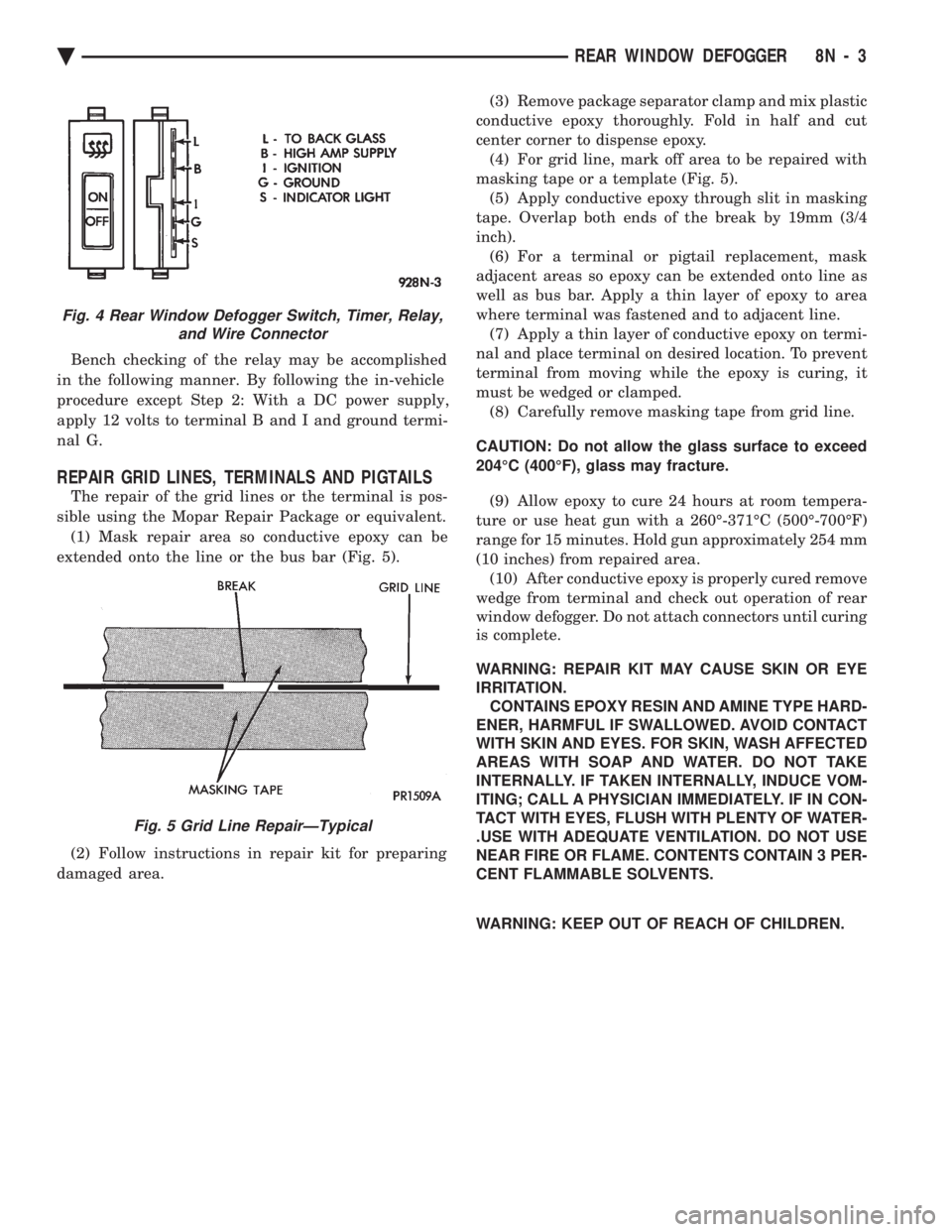
Bench checking of the relay may be accomplished
in the following manner. By following the in-vehicle
procedure except Step 2: With a DC power supply,
apply 12 volts to terminal B and I and ground termi-
nal G.
REPAIR GRID LINES, TERMINALS AND PIGTAILS
The repair of the grid lines or the terminal is pos-
sible using the Mopar Repair Package or equivalent. (1) Mask repair area so conductive epoxy can be
extended onto the line or the bus bar (Fig. 5).
(2) Follow instructions in repair kit for preparing
damaged area. (3) Remove package separator clamp and mix plastic
conductive epoxy thoroughly. Fold in half and cut
center corner to dispense epoxy. (4) For grid line, mark off area to be repaired with
masking tape or a template (Fig. 5). (5) Apply conductive epoxy through slit in masking
tape. Overlap both ends of the break by 19mm (3/4
inch). (6) For a terminal or pigtail replacement, mask
adjacent areas so epoxy can be extended onto line as
well as bus bar. Apply a thin layer of epoxy to area
where terminal was fastened and to adjacent line. (7) Apply a thin layer of conductive epoxy on termi-
nal and place terminal on desired location. To prevent
terminal from moving while the epoxy is curing, it
must be wedged or clamped. (8) Carefully remove masking tape from grid line.
CAUTION: Do not allow the glass surface to exceed
204ÉC (400ÉF), glass may fracture. (9) Allow epoxy to cure 24 hours at room tempera-
ture or use heat gun with a 260É-371ÉC (500É-700ÉF)
range for 15 minutes. Hold gun approximately 254 mm
(10 inches) from repaired area. (10) After conductive epoxy is properly cured remove
wedge from terminal and check out operation of rear
window defogger. Do not attach connectors until curing
is complete.
WARNING: REPAIR KIT MAY CAUSE SKIN OR EYE
IRRITATION. CONTAINS EPOXY RESIN AND AMINE TYPE HARD-
ENER, HARMFUL IF SWALLOWED. AVOID CONTACT
WITH SKIN AND EYES. FOR SKIN, WASH AFFECTED
AREAS WITH SOAP AND WATER. DO NOT TAKE
INTERNALLY. IF TAKEN INTERNALLY, INDUCE VOM-
ITING; CALL A PHYSICIAN IMMEDIATELY. IF IN CON-
TACT WITH EYES, FLUSH WITH PLENTY OF WATER-
.USE WITH ADEQUATE VENTILATION. DO NOT USE
NEAR FIRE OR FLAME. CONTENTS CONTAIN 3 PER-
CENT FLAMMABLE SOLVENTS.
WARNING: KEEP OUT OF REACH OF CHILDREN.
Fig. 4 Rear Window Defogger Switch, Timer, Relay, and Wire Connector
Fig. 5 Grid Line RepairÐTypical
Ä REAR WINDOW DEFOGGER 8N - 3
Page 697 of 2438

DOOR LOCK SYSTEM TEST
For complete testing of the AC, AG, AJ and AY
body automatic door lock systems, refer to the Body
Diagnostic Procedures Manual.
DOOR LOCK MOTOR REPLACEMENT
(1) Remove inside door release handle, window
regulator handle, if equipped and door trim panel. (2) Roll door watershield away from lower rear cor-
ner of door to reveal inside panel access opening. (3) Disconnect link at the motor as required (Fig. 4
through 7).
(4) Disconnect motor lead wires.
(5) Remove motor or latch attaching screws and re-
move motor assembly. (6) For installation reverse above procedures.
DECK LID OPERATION
For vehicles equipped with electric deck lid release.
TEST
(1) Confirm solenoid lead wire is connected and 10
volts or more are available at solenoid. (2) Provide proper ground through latch mounting
screws. (3) Remove latch and examine plunger. Plunger
should spring back when pressed. (4) Insure that solenoid plunger travel is adequate
approximately 16 mm (5/8 inch).
ADJUSTMENT
Adjust deck lid latch and striker so that deck lid
latches with a moderate slam. With ignition switch
in On or Accessory position, push deck lid unlock switch. Should latch fail to lock or unlock replace
latch assembly.
DECK LID PULL-DOWN SYSTEMÐAC and AY
BODIES
C-body vehicles have, as an option, a deck lid
power pull-down mechanism which latches and pulls
the deck lid down the last 25 mm (1 in.) of travel.
The system incorporates a combination latch/deck lid
Fig. 4 Front Power Door Lock MotorsÐAA, AG, AJ and AP Bodies
Fig. 5 Rear Power Door Lock MotorsÐAA and AP Bodies
Fig. 6 Front Power Door Lock MotorsÐAC and AY Bodies
Ä POWER LOCKS 8P - 3
Page 727 of 2438
POWER WINDOWS
CONTENTS
page page
BENCH REPAIR OF REGULATOR AND MOTOR CONVENTIONAL REGULATORS .......... 5
GEAR AND PINION REPLACEMENT AND LUBRICATION ....................... 3
GENERAL INFORMATION .................. 1
MOTOR REPLACEMENT ................... 7
MOTOR REPLACEMENT CONVENTIONAL REGULATORS ....................... 3
MOTOR REPLACEMENTÐFLEX DRIVE REGULATORS ......................... 5 POWER WINDOW CABLE HOUSING/MOTOR RE-
PLACEMENTÐAC and AY BODIES ........ 7
QUARTER WINDOW MOTOR REPLACEMENTÐ AJ BODY ............................. 9
QUARTER WINDOW REPLACEMENTÐ AJ BODY ............................. 8
WINDOW LIFT MOTOR TEST .............. 1
WINDOW LIFT SWITCH TEST .............. 1
WIRING VOLTAGE TEST .................. 1
GENERAL INFORMATION
Front and rear door window lift motors are of the
permanent magnet type. A positive and negative bat-
tery connection to either of the two motor terminals
will cause the motor to rotate in one direction. Re-
versing current through these same two connections
will cause the motor to rotate in the opposite direc-
tion. Each individual motor is grounded through the
master switch by a black wire attached to the left
cowl panel. It is necessary that the window be free to slide up
and down in the glass channels or tubes and tracks.
If the window is not free to move up and down, the
window lift motor will not be able to move the glass. To determine if the glass is free is to disconnect the
regulator from the glass lift plate, and slide the win-
dow up and down by hand. For conventional arm-sec-
tor regulators, after the lift plate is detached from
the glass, it will slide off the regulator drive arm.
Flex-drive regulators may be detached the same way
or by removing one screw holding the flex rack to the
lift plate drive arm.
WIRING VOLTAGE TEST
The following wiring test determines whether or
not voltage is continuous through the body harness
to switch. After removing switch for testing purposes, care-
fully separate multiple terminal block on wiring har-
ness from switch body. With ignition switch ON
connect one lead of test light to black (or gray) wire
terminal and touch other test light lead to tan wire
terminal. If the test light comes on, the wiring cir-
cuit between the battery and switch is functional. If
light does not come on, check 30 amp main fuse (cir- cuit breaker) or for a broken wire. For wiring, spe-
cific connector type and location, refer to Group 8W,
Wiring Diagrams.
WINDOW LIFT SWITCH TEST
For switch testing, remove the switch from its
mounting. Using an ohmmeter, refer to Window
Switch Continuity Charts to determine if continuity
is correct. If the results are not obtained, replace the
switch. AC and AY Bodies are equipped with an Auto-
Down feature. This feature allows the operator to
lower the driver's window without having to hold the
switch in the down position. The Auto-Down feature
can be activated by pressing the down switch past
the first detent (Stop). To test the auto-down feature, operate the window
in the normal up and down mode. If the window
works correctly in the normal mode, but not in the
auto-down mode, replace the switch. To test the window switch (other than Auto-Down
mode), install a known good switch.
WINDOW LIFT MOTOR TEST
(1) Connect positive (+) lead from a test battery to
either of the two motor terminals. (2) Connect negative (-) lead from test battery to
remaining motor terminal. (3) The motor should now rotate in one direction to
either move window up or down. (a) If window happens to already be in full UP
position and motor is connected so as to rotate in
UP direction no movement will be observed. (b) Likewise, motor connected to DOWN direc-
tion rotation, no movement will be observed if win-
dow is already in full DOWN position.
Ä POWER WINDOWS 8S - 1
Page 728 of 2438
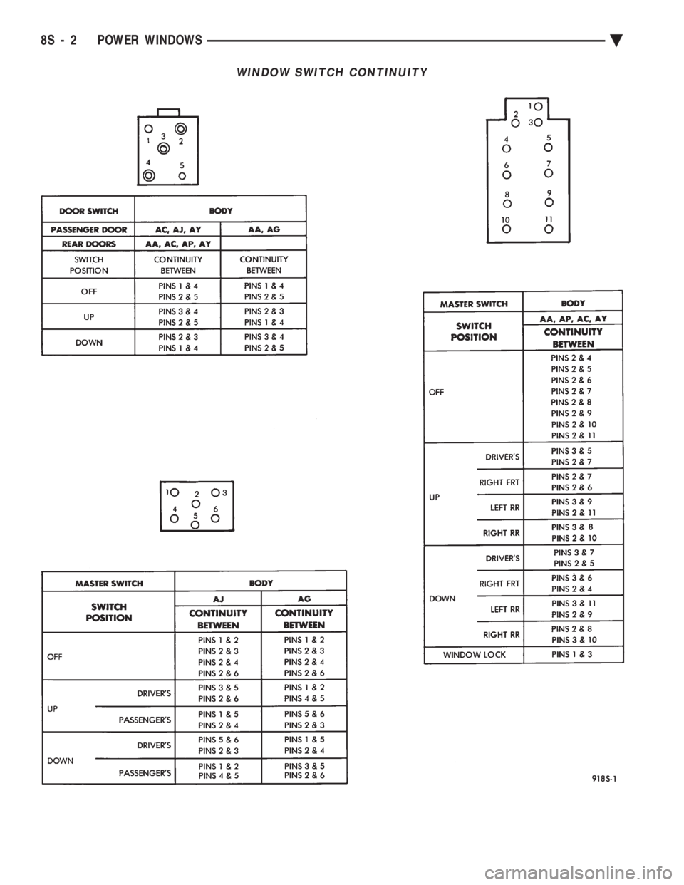
WINDOW SWITCH CONTINUITY
8S - 2 POWER WINDOWS Ä
Page 729 of 2438
(4) Reverse battery leads (steps 1 and 2 above) and
window should now move. If window does not move,
remove motor. See below for motor removal from ve-
hicle. (5) If window moved completely up or down, motor
should be reversed one more time (reverse leads from
step 4) to complete a full window travel inspection.
GEAR AND PINION REPLACEMENT AND
LUBRICATION
The window glass and mechanism have been found
to move freely. The window motor works. But the
glass does not move up or down. The motor gear and
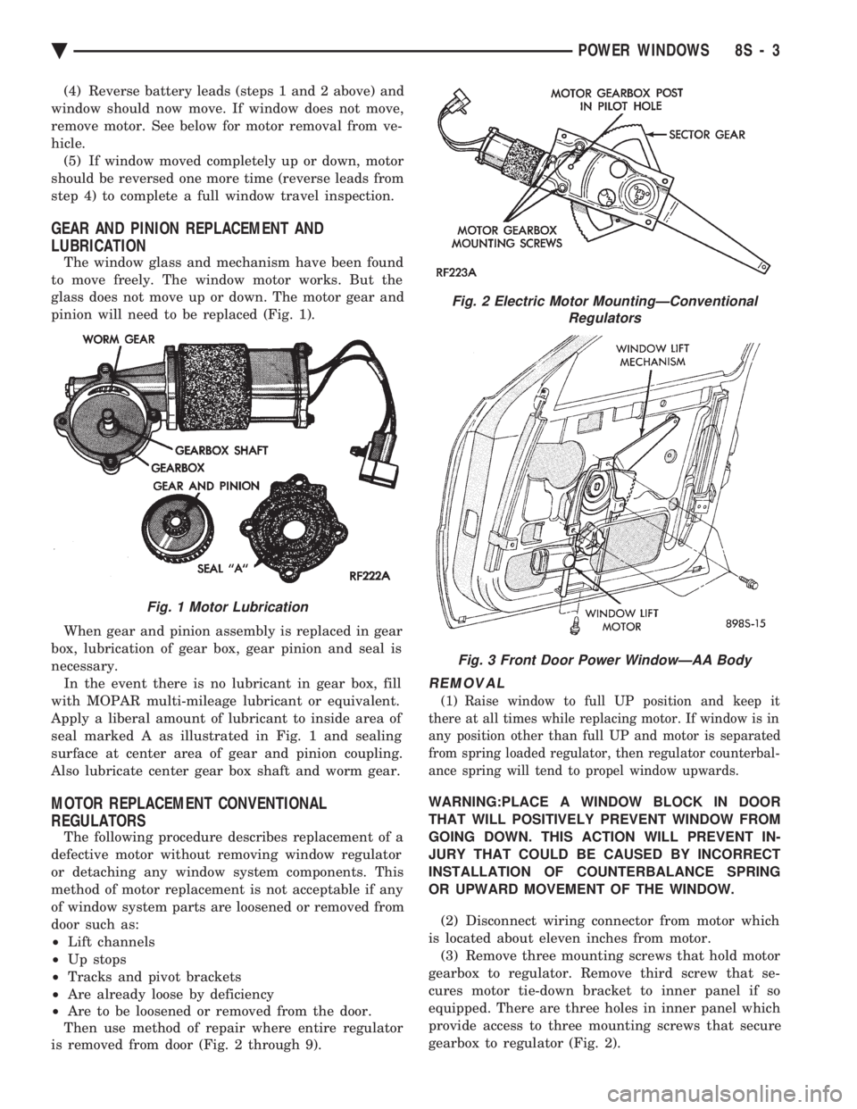
pinion will need to be replaced (Fig. 1).
When gear and pinion assembly is replaced in gear
box, lubrication of gear box, gear pinion and seal is
necessary. In the event there is no lubricant in gear box, fill
with MOPAR multi-mileage lubricant or equivalent.
Apply a liberal amount of lubricant to inside area of
seal marked A as illustrated in Fig. 1 and sealing
surface at center area of gear and pinion coupling.
Also lubricate center gear box shaft and worm gear.
MOTOR REPLACEMENT CONVENTIONAL
REGULATORS
The following procedure describes replacement of a
defective motor without removing window regulator
or detaching any window system components. This
method of motor replacement is not acceptable if any
of window system parts are loosened or removed from
door such as:
² Lift channels
² Up stops
² Tracks and pivot brackets
² Are already loose by deficiency
² Are to be loosened or removed from the door.
Then use method of repair where entire regulator
is removed from door (Fig. 2 through 9).
REMOVAL
(1) Raise window to full UP position and keep it
there at all times while replacing motor. If window is in
any position other than full UP and motor is separated
from spring loaded regulator, then regulator counterbal-
ance spring will tend to propel window upwards.
WARNING:PLACE A WINDOW BLOCK IN DOOR
THAT WILL POSITIVELY PREVENT WINDOW FROM
GOING DOWN. THIS ACTION WILL PREVENT IN-
JURY THAT COULD BE CAUSED BY INCORRECT
INSTALLATION OF COUNTERBALANCE SPRING
OR UPWARD MOVEMENT OF THE WINDOW.
(2) Disconnect wiring connector from motor which
is located about eleven inches from motor. (3) Remove three mounting screws that hold motor
gearbox to regulator. Remove third screw that se-
cures motor tie-down bracket to inner panel if so
equipped. There are three holes in inner panel which
provide access to three mounting screws that secure
gearbox to regulator (Fig. 2).
Fig. 1 Motor Lubrication
Fig. 2 Electric Motor MountingÐConventional Regulators
Fig. 3 Front Door Power WindowÐAA Body
Ä POWER WINDOWS 8S - 3
Page 730 of 2438
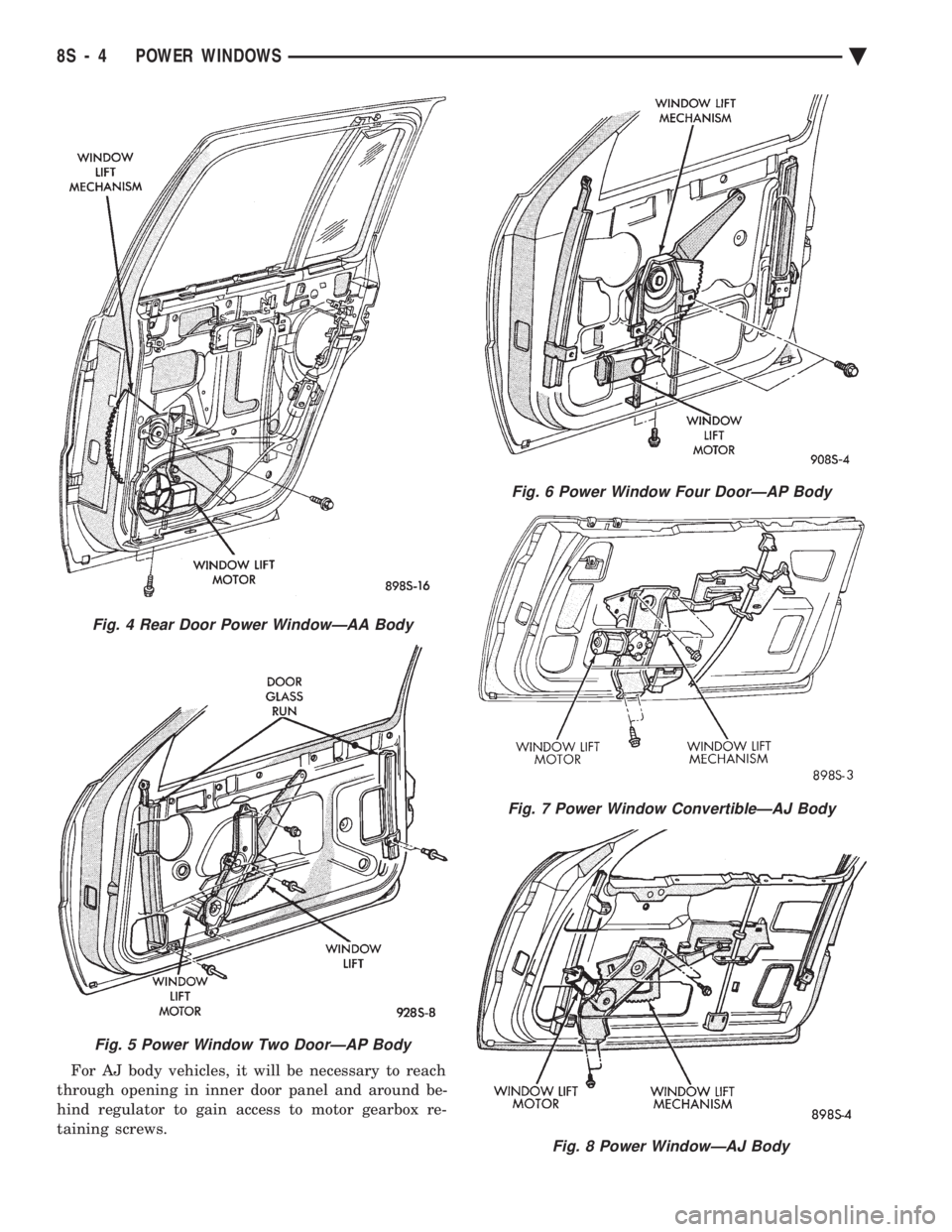
For AJ body vehicles, it will be necessary to reach
through opening in inner door panel and around be-
hind regulator to gain access to motor gearbox re-
taining screws.
Fig. 6 Power Window Four DoorÐAP Body
Fig. 7 Power Window ConvertibleÐAJ Body
Fig. 8 Power WindowÐAJ Body
Fig. 4 Rear Door Power WindowÐAA Body
Fig. 5 Power Window Two DoorÐAP Body
8S - 4 POWER WINDOWS Ä