1993 CHEVROLET PLYMOUTH ACCLAIM key battery
[x] Cancel search: key batteryPage 454 of 2438
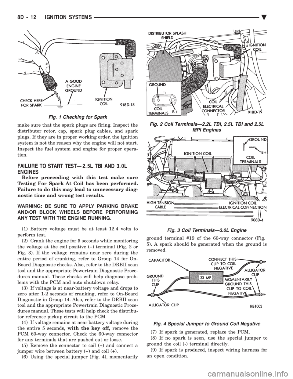
make sure that the spark plugs are firing. Inspect the
distributor rotor, cap, spark plug cables, and spark
plugs. If they are in proper working order, the ignition
system is not the reason why the engine will not start.
Inspect the fuel system and engine for proper opera-
tion.
FAILURE TO START TESTÐ2.5L TBI AND 3.0L
ENGINES
Before proceeding with this test make sure
Testing For Spark At Coil has been performed.
Failure to do this may lead to unnecessary diag-
nostic time and wrong test results.
WARNING: BE SURE TO APPLY PARKING BRAKE
AND/OR BLOCK WHEELS BEFORE PERFORMING
ANY TEST WITH THE ENGINE RUNNING.
(1) Battery voltage must be at least 12.4 volts to
perform test. (2) Crank the engine for 5 seconds while monitoring
the voltage at the coil positive (+) terminal (Fig. 2 or
Fig. 3). If the voltage remains near zero during the
entire period of cranking, refer to Group 14 for On-
Board Diagnostic checks. Also, refer to the DRBII scan
tool and the appropriate Powertrain Diagnostic Proce-
dures manual. These checks will help diagnose prob-
lems with the PCM and auto shutdown relay. (3) If voltage is at near-battery voltage and drops to
zero after 1-2 seconds of cranking, refer to On-Board
Diagnostic in Group 14. Also, refer to the DRBII scan
tool and the appropriate Powertrain Diagnostic Proce-
dures manual. These tests will help check the distribu-
tor reference pickup circuit to the PCM. (4) If voltage remains at near battery voltage during
the entire 5 seconds, with the key off,remove the
PCM 60-way connector. Check the 60-way connector
for any terminals that are pushed out or loose. (5) Remove the connector to coil (+) and connect a
jumper wire between battery (+) and coil (+). (6) Using the special jumper (Fig. 4), momentarily ground terminal #19 of the 60-way connector (Fig.
5). A spark should be generated when the ground is
removed.
(7) If spark is generated, replace the PCM.
(8) If no spark is seen, use the special jumper to
ground the coil (-) terminal directly. (9) If spark is produced, inspect wiring harness for
an open condition.
Fig. 2 Coil TerminalsÐ2.2L TBI, 2.5L TBI and 2.5L MPI Engines
Fig. 3 Coil TerminalsÐ3.0L Engine
Fig. 4 Special Jumper to Ground Coil Negative
Fig. 1 Checking for Spark
8D - 12 IGNITION SYSTEMS Ä
Page 478 of 2438
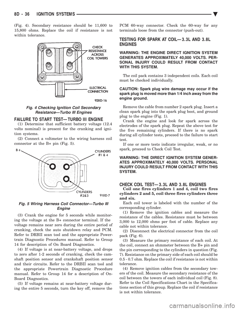
(Fig. 4). Secondary resistance should be 11,600 to
15,800 ohms. Replace the coil if resistance is not
within tolerance.
FAILURE TO START TESTÐTURBO III ENGINE
(1) Determine that sufficient battery voltage (12.4
volts nominal) is present for the cranking and igni-
tion systems. (2) Connect a voltmeter to the wiring harness coil
connector at the B+ pin (Fig. 5).
(3) Crank the engine for 5 seconds while monitor-
ing the voltage at the B+ connector terminal. If the
voltage remains near zero during the entire period of
cranking, check the auto shutdown relay and PCM.
Refer to DRBII scan tool and the appropriate Power-
train Diagnostic Procedures manual. Refer to Group
14 for description of On Board Diagnostics. (4) If voltage is at near-battery voltage, and drops
to zero after 1-2 seconds of cranking, check the cam-
shaft position sensor and crankshaft position sensor
and their circuits. Refer to the DRBII scan tool and
the appropriate Powertrain Diagnostic Procedure
manual. Refer to Group 14 for a description of On-
Board Diagnostics. (5) If voltage remains at near-battery voltage dur-
ing the entire 5 seconds, turn the key off, remove the PCM 60-way connector. Check the 60-way for any
terminals loose from the connector (push-out).
TESTING FOR SPARK AT COILÐ3.3L AND 3.8L
ENGINES
WARNING: THE ENGINE DIRECT IGNITION SYSTEM
GENERATES APPROXIMATELY 40,000 VOLTS. PER-
SONAL INJURY COULD RESULT FROM CONTACT
WITH THIS SYSTEM.
The coil pack contains 3 independent coils. Each coil
must be checked individually.
CAUTION: Spark plug wire damage may occur if the
spark plug is moved more than 1/4 inch away from the
engine ground.
Remove the cable from number 2 spark plug. Insert a
clean spark plug into the spark plug boot, and ground
plug to the engine (Fig. 1). Crank the engine and look for spark across the
electrodes of the spark plug. Repeat the above test for
the five remaining cylinders. If there is no spark
during all cylinder tests, proceed to the failure to start
test. If one or more tests indicate irregular, weak, or no
spark, proceed to Check Coil Test.
WARNING: THE DIRECT IGNITION SYSTEM GENER-
ATES APPROXIMATELY 40,000 VOLTS. PERSONAL
INJURY COULD RESULT FROM CONTACT WITH THIS
SYSTEM.
CHECK COIL TESTÐ3.3L AND 3.8L ENGINES
Coil one fires cylinders 1 and 4, coil two fires
cylinders 2 and 5, coil three fires cylinders three
and six. Each coil tower is labeled with the number of the
corresponding cylinder. (1) Remove the ignition cables and measure the
resistance of the cables. Resistance must be between
3,000 to 12,000 ohms per foot of cable. Replace any
cable not within tolerance. (2) Disconnect the electrical connector from the coil
pack (Fig. 6). (3) Measure the primary resistance of each coil. At
the coil, connect an ohmmeter between the B+ pin and
the pin corresponding to the cylinders in question (Fig.
7). Resistance on the primary side of each coil should be
0.5 - 0.7 ohm. Replace the coil if resistance is not within
tolerance. (4) Remove ignition cables from the secondary tow-
ers of the coil. Measure the secondary resistance of the
coil between the towers of each individual coil (Fig. 8).
Refer to the Coil Specifications Chart in the Specifica-
tions section of this group. Replace the coil if resistance
is not within tolerance.
Fig. 4 Checking Ignition Coil Secondary ResistanceÐTurbo III Engines
Fig. 5 Wiring Harness Coil ConnectorÐTurbo III Engine
8D - 36 IGNITION SYSTEMS Ä
Page 479 of 2438

FAILURE TO START TEST
This no-start test checks the camshaft position sen-
sor and crankshaft position sensor. The powertrain control module (PCM) supplies 8.0
volts to the camshaft position sensor and crankshaft
position sensor through one circuit. If the 8.0-volt
supply circuit shorts to ground, neither sensor will
produce a signal (output voltage to the PCM). When the ignition key is turned and left in the On
position , the PCM automatically energizes the auto shutdown (ASD) relay. However, the PCM de-energizes
the relay within one second because it has not received
a crankshaft position sensor signal indicating engine
rotation.
During cranking, the ASD relay will not energize
until the PCM receives a crankshaft signal. Secondly,
the ASD relay remains energized only if the PCM
senses a camshaft position sensor signal immediately
after detecting the crankshaft position sensor signal. (1) Check battery voltage. Voltage should approxi-
mately 12.66 volts or higher to perform failure to start
test. (2) Disconnect the harness connector from the coil
pack (Fig. 2). (3) Connect a test light to the B+ (battery voltage)
terminal of the coil electrical connector and ground.
The wire for the B+ terminal is dark green with a black
tracer. (4) Turn the ignition key to the ON position.The
test light should flash On and then Off. Do not turn
the Key to off position, leave it in the On position .
(a) If the test light flashes momentarily, the PCM
grounded the auto shutdown (ASD) relay. Proceed to
step 5. (b) If the test light did not flash, the ASD relay did
not energize. The cause is either the relay or one of
the relay circuits. Use the DRBII scan tool to test the
ASD relay and circuits. Refer to the appropriate
Powertrain Diagnostics Procedure Manual. Refer to
the wiring diagrams section for circuit information.
(5) Crank the engine. If the key was placed in the off
position after step 4, place the key in the On position
before cranking. Wait for the test light to flash once,
then crank the engine. (a) If the test light momentarily flashes during
cranking, the PCM is not receiving a camshaft posi-
tion sensor signal. Use the DRBII scan tool to test the
camshaft position sensor and sensor circuits. Refer to
the appropriate Powertrain Diagnostics Procedure
Manual. Refer to the wiring diagrams section for
circuit information. (b) If the test light did not flash during cranking,
unplug the camshaft position sensor connector. Turn
the ignition key to the off position. Turn the key to
the On position, wait for the test light to momen-
tarily flash once, then crank the engine. If the test
light momentarily flashes, the camshaft position
sensor is shorted and must be replaced. If the light
did not flash, the cause of the no-start is in either the
crankshaft position sensor/camshaft position sensor
8.0-volt supply circuit, or the crankshaft position
sensor 5-volt output or ground circuits. Use the
DRBII scan tool to test the crankshaft position sen-
sor and the sensor circuits.
Fig. 6 Ignition Coil Electrical Connection
Fig. 7 Ignition Coil Terminal Identification
Fig. 8 Checking Ignition Coil Secondary Resistance
Ä IGNITION SYSTEMS 8D - 37
Page 487 of 2438
IGNITION SWITCH
IGNITION SWITCH AND KEY CYLINDER SERVICE
The ignition switch is located on the steering col-
umn. The Key In Switch is located in the ignition
switch module. For diagnosis of the Key In Switch,
refer to Section 8M.
REMOVAL
If the vehicle has a floor mounted gear shifter,
place the selector in the Park position. (1) Disconnect negative cable from battery.
(2) If the vehicle has a tilt column, remove the tilt
lever by turning it counterclockwise. (3) Remove upper and lower covers from steering
column.
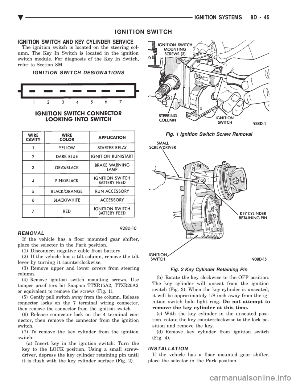
(4) Remove ignition switch mounting screws. Use
tamper proof torx bit Snap-on TTXR15A2, TTXR20A2
or equivalent to remove the screws (Fig. 1). (5) Gently pull switch away from the column. Release
connector locks on the 7 terminal wiring connector,
then remove the connector from the ignition switch.
(6) Release connector lock on the 4 terminal con-
nector, then remove the connector from the ignition
switch. (7) To remove the key cylinder from the ignition
switch: (a) Insert key in the ignition switch. Turn the
key to the LOCK position. Using a small screw-
driver, depress the key cylinder retaining pin until
it is flush with the key cylinder surface (Fig. 2). (b) Rotate the key clockwise to the OFF position.
The key cylinder will unseat from the ignition
switch (Fig. 3). When the key cylinder is unseated,
it will be approximately 1/8 inch away from the ig-
nition switch halo light ring. Do not attempt to
remove the key cylinder at this time. (c) With the key cylinder in the unseated posi-
tion, rotate the key counterclockwise to the lock po-
sition and remove the key. (d) Remove key cylinder from ignition switch
(Fig. 4).
INSTALLATION
If the vehicle has a floor mounted gear shifter,
place the selector in the Park position.
IGNITION SWITCH DESIGNATIONS
Fig. 1 Ignition Switch Screw Removal
Fig. 2 Key Cylinder Retaining Pin
Ä IGNITION SYSTEMS 8D - 45
Page 488 of 2438
(1) Connect electrical connectors to the ignition
switch. Make sure that the switch locking tabs are fully
seated in the wiring connectors. (2) Before attaching the ignition switch to a tilt
steering column, the transaxle shifter must be in the
Park position. Also the park lock dowel pin and the
column lock flag must be properly indexed before
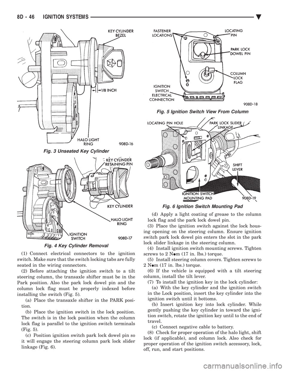
installing the switch (Fig. 5). (a) Place the transaxle shifter in the PARK posi-
tion. (b) Place the ignition switch in the lock position.
The switch is in the lock position when the column
lock flag is parallel to the ignition switch terminals
(Fig. 5). (c) Position ignition switch park lock dowel pin so
it will engage the steering column park lock slider
linkage (Fig. 6). (d) Apply a light coating of grease to the column
lock flag and the park lock dowel pin.
(3) Place the ignition switch against the lock hous-
ing opening on the steering column. Ensure ignition
switch park lock dowel pin enters the slot in the park
lock slider linkage in the steering column. (4) Install ignition switch mounting screws. Tighten
screws to 2 N Im (17 in. lbs.) torque.
(5) Install steering column covers. Tighten screws to
2N Im (17 in. lbs.) torque.
(6) If the vehicle is equipped with a tilt steering
column, install the tilt lever. (7) To install the ignition key in the lock cylinder:(a) With the key cylinder and the ignition switch
in the Lock position, insert the key cylinder into the
ignition switch until it bottoms. (b) Insert ignition key into lock cylinder. While
gently pushing the key cylinder in toward the igni-
tion switch, rotate the ignition key until to the end of
travel. (c) Connect negative cable to battery.
(8) Check for proper operation of the halo light, shift
lock (if applicable), and column lock. Also check for
proper operation of the ignition switch accessory, lock,
off, run, and start positions.
Fig. 3 Unseated Key Cylinder
Fig. 4 Key Cylinder Removal
Fig. 5 Ignition Switch View From Column
Fig. 6 Ignition Switch Mounting Pad
8D - 46 IGNITION SYSTEMS Ä
Page 501 of 2438

(3) When testing temperature, allow the engine to
run until the vehicle reaches a normal operating
temperature. Turn ignition OFF, and remove gauge
from cluster. (a) Testing oil pressure gauge, engine needs to
be running. (b) Measure and record the resistance between
sending unit pin and ground pin of the gauge in
question. Refer to Gauge Calibration. (c) It is important to have the same engine tem-
perature and engine speed when checking temper-
ature and oil pressure gauges position. The time
between gauge position reading and sending unit
measuring should be kept to a minimum. (d) If resistance and gauge position are not sim-
ilar, replace gauge. (e) If OK, test resistance from the sending unit
to the cluster connector. (f) If resistance reading is different, check
printed circuit board for contact to cluster connec-
tor. (g) If OK and contacts are not distorted, replace
printed circuit board. (h) If everything checks out OK, refer to sending
unit test.
(4) If fuel gauge does not meet specifications, refer
to Group 14, Fuel for the test procedure.
GAUGE CALIBRATION
(1) Remove the gauge.
(2) Check for ignition voltage and ground to the
gauge. (3) With the ignition key in the OFF position, re-
place gauge. Turn the ignition key to the ON posi-
tion. To test oil pressure gauge engine must be
running. When testing oil or temperature gauge the
engine should be at normal operating temperature.
Record the gauge position. (4) Remove gauge and record the resistance be-
tween the sending unit pin and the gauge ground
pin. When checking gauges, it is important to have
the same engine temperature and speed when noting
gauge position. The time between gauge reading and
measuring should be kept to a minimum. (5) The Gauge Resistance Chart (Fig. 24), is gen-
eral guidelines for checking the gauge position
against the sending unit resistance. Because of only a few specific points of gauge posi-
tion versus sending unit resistance, a good estimate
is need when the resistance falls between gradua-
tions. Even when the resistance corresponds to grad-
uations, the gauge has a tolerance of 64 ohms.
Volt gauge: The calibration dot on the volt gauge
corresponds to 13 volts between the gauge ignition
and ground pins. If voltage varies from this, estimate
proper gauge position with input voltage.
TACHOMETER REPLACEMENT
(1) Remove cluster, radio and rear window defog-
ger bezels and mask/lens assembly. (2) Remove screws attaching tachometer to cluster
housing. (3) Pull tachometer rearward to remove.
(4) For installation reverse above procedures.
TACHOMETER CIRCUIT TESTING
(1) Remove cluster, radio and rear window defog-
ger bezels and mask/lens assembly. (2) Check for battery voltage at cavity A of the in-
strument cluster black connector. (3) With the ignition in the ON position, check for
battery voltage at cavity C of the black connector
(Fig. 25).
Fig. 24 Gauge Resistance
Fig. 25 Printed Circuit Board 11-Way Connector
Ä INSTRUMENT PANEL AND GAUGES 8E - 9
Page 516 of 2438

MESSAGE CENTER
The message center is a car graphic warning lamp
module. This conventional warning system and lo-
cated above the headlamp switch.
ELECTRONIC DIGITAL CLOCK
The electronic digital clock is in the radio. The
clock and radio each use the display panel built into
the radio. A digital readout indicates the time in
hours and minutes whenever the ignition switch is in
the ON or ACC position. When the ignition switch is in the OFF position, or
when the radio frequency is being displayed, time
keeping is accurately maintained. The procedure for setting the clock varies slightly
with each radio. The correct procedure is described
under the individual radio operating instructions re-
ferred to in the Owner's Manual supplied with the
vehicle.
AIR BAG WARNING SYSTEM
For testing of this system refer to Group 8M, Re-
straint Systems.
MECHANICAL CLUSTER AND GAUGE SERVICE
CAUTION: Disconnect negative battery cable, in en-
gine compartment, before servicing instrument
panel. When power is required for test purposes,
reconnect battery cable for the test only.
Disconnect negative battery cable after test and be-
fore continuing service procedures.
SENDING UNIT TEST
When a problem occurs with a cluster gauge, be-
fore disassembling the cluster to check the gauge,
check for a defective sending unit or wiring. (1) Sending units and wiring can be checked by
grounding the connector leads, at the sending unit,
in the vehicle. (2) With the ignition in the ON position; a
grounded input will cause the oil, fuel or tempera-
ture gauge to read at or above maximum.
CHECK GAUGES WARNING LAMP TESTS
The check gauges warning lamp is illuminated by
the low oil pressure sending unit switch or the body
controller when there is high temperature or charg-
ing system failure. To test the lamp, turn ignition key to the ON po-
sition without starting the vehicle. The low oil pres-
sure switch is grounded and the light will be on
indefinitely. If the lamp fails to light, pull the cluster and check
the following: (a) Continuity between ground and check gauge
pin J (Fig. 3). (b) Proper contact between the gauge pins and
wiring harness and printed circuit board pins. (c) If there is ground and proper pin contact, re-
place lamp. (d) If there is no continuity, check the low oil
pressure sending unit switch (Fig. 4 and 5).
To test the switch disconnect the switch electrical
connector. Attach positive lead of an ohmmeter to
the switch terminal for the gray (GY) wire and the
negative lead to an engine ground. With the engine
Fig. 3 Mechanical Cluster Connectors
8E - 24 INSTRUMENT PANEL AND GAUGES Ä
Page 520 of 2438
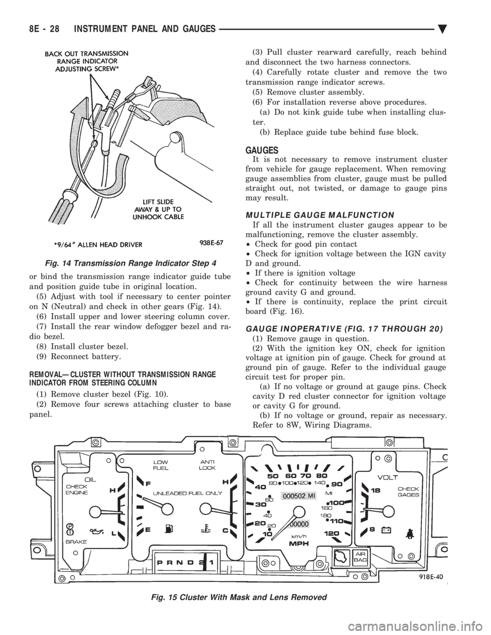
or bind the transmission range indicator guide tube
and position guide tube in original location.(5) Adjust with tool if necessary to center pointer
on N (Neutral) and check in other gears (Fig. 14). (6) Install upper and lower steering column cover.
(7) Install the rear window defogger bezel and ra-
dio bezel. (8) Install cluster bezel.
(9) Reconnect battery.
REMOVALÐCLUSTER WITHOUT TRANSMISSION RANGE
INDICATOR FROM STEERING COLUMN
(1) Remove cluster bezel (Fig. 10).
(2) Remove four screws attaching cluster to base
panel. (3) Pull cluster rearward carefully, reach behind
and disconnect the two harness connectors. (4) Carefully rotate cluster and remove the two
transmission range indicator screws. (5) Remove cluster assembly.
(6) For installation reverse above procedures. (a) Do not kink guide tube when installing clus-
ter. (b) Replace guide tube behind fuse block.
GAUGES
It is not necessary to remove instrument cluster
from vehicle for gauge replacement. When removing
gauge assemblies from cluster, gauge must be pulled
straight out, not twisted, or damage to gauge pins
may result.
MULTIPLE GAUGE MALFUNCTION
If all the instrument cluster gauges appear to be
malfunctioning, remove the cluster assembly.
² Check for good pin contact
² Check for ignition voltage between the IGN cavity
D and ground.
² If there is ignition voltage
² Check for continuity between the wire harness
ground cavity G and ground.
² If there is continuity, replace the print circuit
board (Fig. 16).
GAUGE INOPERATIVE (FIG. 17 THROUGH 20)
(1) Remove gauge in question.
(2) With the ignition key ON, check for ignition
voltage at ignition pin of gauge. Check for ground at
ground pin of gauge. Refer to the individual gauge
circuit test for proper pin. (a) If no voltage or ground at gauge pins. Check
cavity D red cluster connector for ignition voltage
or cavity G for ground. (b) If no voltage or ground, repair as necessary.
Refer to 8W, Wiring Diagrams.
Fig. 15 Cluster With Mask and Lens Removed
Fig. 14 Transmission Range Indicator Step 4
8E - 28 INSTRUMENT PANEL AND GAUGES Ä