1993 CHEVROLET PLYMOUTH ACCLAIM key battery
[x] Cancel search: key batteryPage 1906 of 2438
S/C Vacuum Solenoid
A/C Clutch Relay
EGR Solenoid
Auto Shutdown Relay
Radiator Fan Relay
Purge Solenoid
Malfunction Indicator Lamp (Check Engine Lamp)
STATE DISPLAY SENSORS
Connect the DRBII scan tool to the vehicle and ac-
cess the State Display screen. Then access Sensor
Display. The following is a list of the engine control
system functions accessible through the Sensor Dis-
play screen. Oxygen Sensor Signal
Engine Coolant Temperature
Engine Coolant Temp Sensor
Throttle Position
Minimum Throttle
Battery Voltage
MAP Sensor Reading
Idle Air Control Motor Position
Adaptive Fuel Factor
Barometric Pressure
Min Airflow Idle Spd (speed)
Engine Speed
DIS Sensor Status
Fault #1 Key-On Info
Module Spark Advance
Speed Control Target
Fault #2 Key-on Info
Fault #3 Key-on Info
Speed Control Status
Speed Control Switch Voltage
Charging System Goal
Theft Alarm Status
Map Sensor Voltage
Vehicle Speed
Oxygen Sensor State
MAP Gauge Reading
Throttle Opening (percentage)
Total Spark Advance
CIRCUIT ACTUATION TEST MODE
The circuit actuation test mode checks for proper
operation of output circuits or devices which the pow-
ertrain control module (PCM) cannot internally rec-
ognize. The PCM can attempt to activate these
outputs and allow an observer to verify proper oper-
ation. Most of the tests provide an audible or visual
indication of device operation (click of relay contacts,
spray fuel, etc.). Except for intermittent conditions, if
a device functions properly during testing, assume
the device, its associated wiring, and driver circuit
working correctly.
OBTAINING CIRCUIT ACTUATION TEST
Connect the DRBII scan tool to the vehicle and ac-
cess the Actuators screen. The following is a list of
the engine control system functions accessible
through Actuators screens. Stop All Tests
Ignition Coil #1
Ignition Coil #2
Ignition Coil #3
Fuel Injector #1
Fuel Injector #2
Fuel Injector #3
Fuel Injector #4
Fuel Injector #5
Fuel Injector #6
Idle Air Control Motor Open/Close
Radiator Fan Relay
A/C Clutch Relay
Auto Shutdown Relay
EVAP Purge Solenoid
S/C Servo Solenoids
Generator Field
EGR Solenoid
All Solenoids/Relays
ASD Fuel System Test
Speed Control Vacuum Solenoid
Speed Control Vent Solenoid
THROTTLE BODY MINIMUM AIR FLOW CHECK
PROCEDURE
(1) Warm engine in Park or Neutral until the cool-
ing fan has cycled on and off at least once. (2) Ensure that all accessories are off.
(3) Shut off engine.
(4) Disconnect the PCV valve hose from the intake
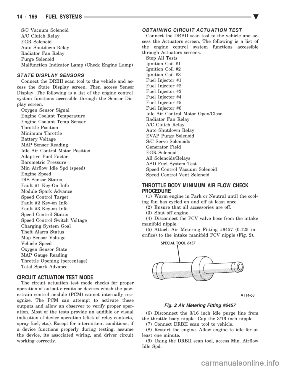
manifold nipple. (5) Attach Air Metering Fitting #6457 (0.125 in.
orifice) to the intake manifold PCV nipple (Fig. 2).
(6) Disconnect the 3/16 inch idle purge line from
the throttle body nipple. Cap the 3/16 inch nipple. (7) Connect DRBII scan tool to vehicle.
(8) Restart the engine. Allow engine to idle for at
least one minute. (9) Using the DRBII scan tool, access Min. Airflow
Idle Spd.
Fig. 2 Air Metering Fitting #6457
14 - 166 FUEL SYSTEMS Ä
Page 1913 of 2438
(5) Install fuel tube retaining bracket screw.
Tighten screw to 4 N Im (35 in. lbs.) torque.
(6) Connect electrical connectors to camshaft posi-
tion sensor, coolant temperature sensor and engine
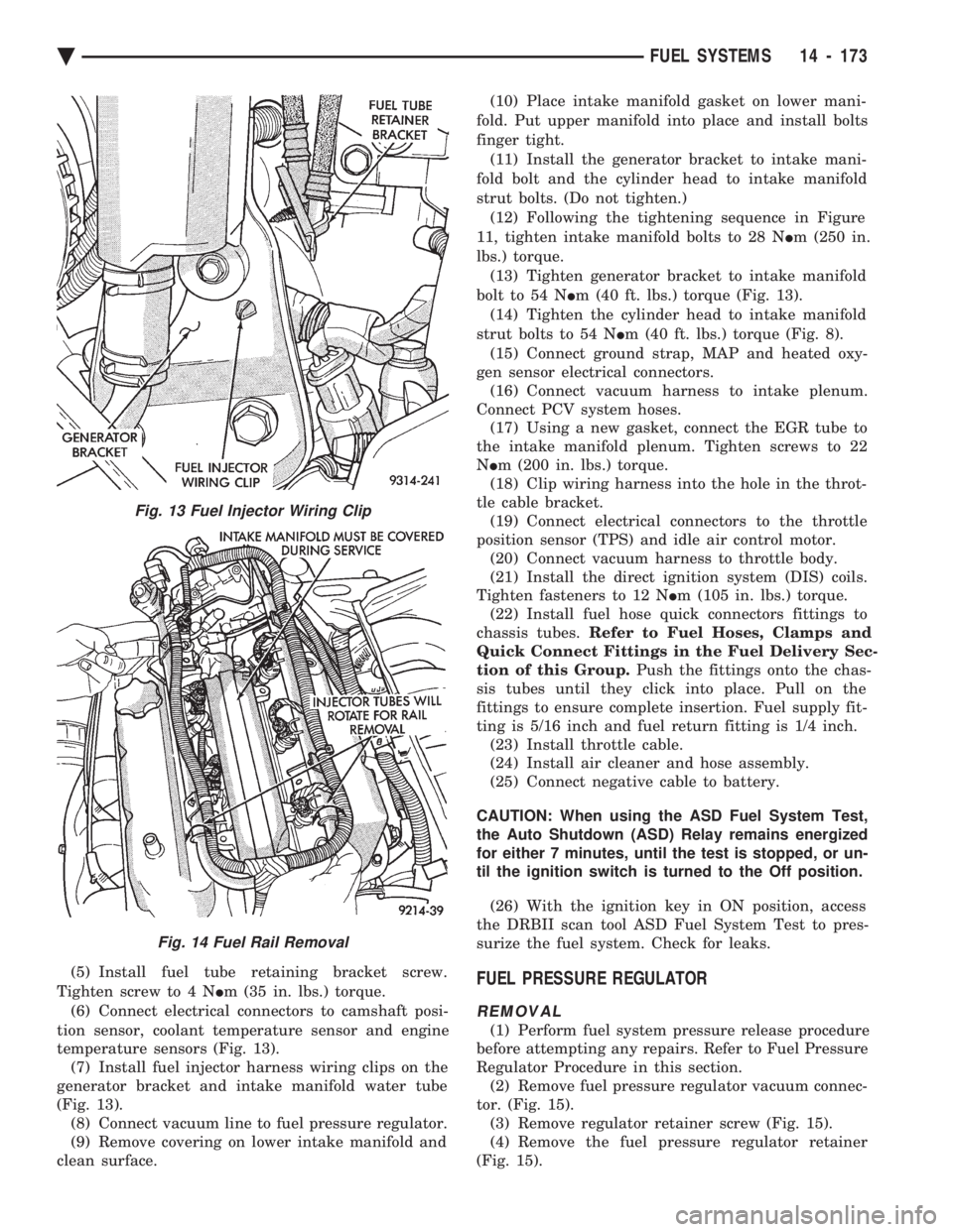
temperature sensors (Fig. 13). (7) Install fuel injector harness wiring clips on the
generator bracket and intake manifold water tube
(Fig. 13). (8) Connect vacuum line to fuel pressure regulator.
(9) Remove covering on lower intake manifold and
clean surface. (10) Place intake manifold gasket on lower mani-
fold. Put upper manifold into place and install bolts
finger tight. (11) Install the generator bracket to intake mani-
fold bolt and the cylinder head to intake manifold
strut bolts. (Do not tighten.) (12) Following the tightening sequence in Figure
11, tighten intake manifold bolts to 28 N Im (250 in.
lbs.) torque. (13) Tighten generator bracket to intake manifold
bolt to 54 N Im (40 ft. lbs.) torque (Fig. 13).
(14) Tighten the cylinder head to intake manifold
strut bolts to 54 N Im (40 ft. lbs.) torque (Fig. 8).
(15) Connect ground strap, MAP and heated oxy-
gen sensor electrical connectors. (16) Connect vacuum harness to intake plenum.
Connect PCV system hoses. (17) Using a new gasket, connect the EGR tube to
the intake manifold plenum. Tighten screws to 22
N Im (200 in. lbs.) torque.
(18) Clip wiring harness into the hole in the throt-
tle cable bracket. (19) Connect electrical connectors to the throttle
position sensor (TPS) and idle air control motor. (20) Connect vacuum harness to throttle body.
(21) Install the direct ignition system (DIS) coils.
Tighten fasteners to 12 N Im (105 in. lbs.) torque.
(22) Install fuel hose quick connectors fittings to
chassis tubes. Refer to Fuel Hoses, Clamps and
Quick Connect Fittings in the Fuel Delivery Sec-
tion of this Group. Push the fittings onto the chas-
sis tubes until they click into place. Pull on the
fittings to ensure complete insertion. Fuel supply fit-
ting is 5/16 inch and fuel return fitting is 1/4 inch. (23) Install throttle cable.
(24) Install air cleaner and hose assembly.
(25) Connect negative cable to battery.
CAUTION: When using the ASD Fuel System Test,
the Auto Shutdown (ASD) Relay remains energized
for either 7 minutes, until the test is stopped, or un-
til the ignition switch is turned to the Off position.
(26) With the ignition key in ON position, access
the DRBII scan tool ASD Fuel System Test to pres-
surize the fuel system. Check for leaks.FUEL PRESSURE REGULATOR
REMOVAL
(1) Perform fuel system pressure release procedure
before attempting any repairs. Refer to Fuel Pressure
Regulator Procedure in this section. (2) Remove fuel pressure regulator vacuum connec-
tor. (Fig. 15). (3) Remove regulator retainer screw (Fig. 15).
(4) Remove the fuel pressure regulator retainer
(Fig. 15).
Fig. 13 Fuel Injector Wiring Clip
Fig. 14 Fuel Rail Removal
Ä FUEL SYSTEMS 14 - 173
Page 1952 of 2438
(16) Connect the battery ground (negative) cable.
Test the operation of the lights and horns. If applica-
ble, reset the clock and radio.
STEERING COLUMN COMPONENT SERVICE
The Acustar tilt and standard steering columns
(Fig.1) have been designed to be serviced as an as-
sembly; less wiring, switches, shrouds, steering
wheel, etc. Also most steering column components
can be serviced without removing the steering col-
umn from the vehicle. For additional information on
electrical components refer to Group 8H Electrical.
GEAR SHIFT LEVER
The gear shift lever (if equipped) is a serviceable
component of the Acustar steering column assembly.
REMOVE (1) Support the steering column assembly as
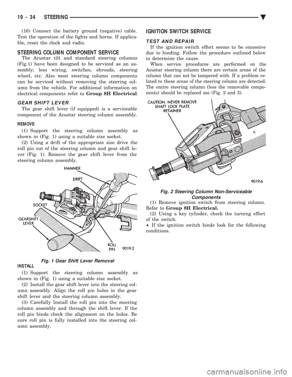
shown in (Fig. 1) using a suitable size socket. (2) Using a drift of the appropriate size drive the
roll pin out of the steering column and gear shift le-
ver (Fig. 1). Remove the gear shift lever from the
steering column assembly.
INSTALL (1) Support the steering column assembly as
shown in (Fig. 1) using a suitable size socket. (2) Install the gear shift lever into the steering col-
umn assembly. Align the roll pin holes in the gear
shift lever and the steering column assembly. (3) Carefully Install the roll pin into the steering
column assembly and through the shift lever. If the
roll pin binds check the alignment on the holes. Be
sure roll pin is fully installed into the steering col-
umn assembly.
IGNITION SWITCH SERVICE
TEST AND REPAIR
If the ignition switch effort seems to be excessive
due to binding. Follow the procedure outlined below
to determine the cause.
When service procedures are performed on the
Acustar steering column there are certain areas of the
column that can not be tampered with. If a problem re-
lated to these areas of the steering column are detected.
The entire steering column (less the removable compo-
nents) should be replaced see (Fig. 2 and 3).
(1) Remove ignition switch from steering column.
Refer to Group 8H Electrical.
(2) Using a key cylinder, check the turning effort
of the switch.
² If the ignition switch binds look for the following
conditions.
Fig. 1 Gear Shift Lever Removal
Fig. 2 Steering Column Non-Serviceable Components
19 - 34 STEERING Ä
Page 2105 of 2438
41TE ON-BOARD DIAGNOSTICS INDEX
page page
CCD Bus .............................. 145
Diagnostic Trouble Code Charts ............ 146
Diagnostic Trouble Codes ................. 145
DRB II Scan Tool ....................... 146 General Information
...................... 145
Limp-In Mode .......................... 145
On-Board Diagnostics Information ........... 145
GENERAL INFORMATION
The information in this manual is designed to help
the technician understand and repair the transaxle
with the aid of the built in on-board diagnostics. Chrysler Corporation has developed a com-
plete set of diagnostic manuals which cover the
diagnosis of the 41TE transaxle. They have been
designed to make transaxle diagnosis accurate
and simple. Use these manuals with the DRB II
scan tool and the latest cartridge, when diagnos-
ing transaxle problems.
ON-BOARD DIAGNOSTICS INFORMATION
The 41TE transaxle is controlled and monitored by
the transmission control module. The transmission
control module monitors critical input and output
circuits within the transaxle. Some circuits are tested continuously; others are
checked only under certain conditions. Each circuit
monitored by the transmission control module has a
corresponding fault message assigned to it that can be
read with the DRB II scan tool. If the on-board diagnostic system senses that one of
the circuits is malfunctioning, the corresponding code
is stored in memory. If the malfunction goes away after
the code is stored, the transmission control module will
erase the code after 75 key cycles.
CCD BUS
In order to diagnose the 41TE transaxle, diagnostic
trouble codes in the transmission control module's
memory should be read. Use the Diagnostic Readout
Box (DRB II) scan tool to read codes. If more than one
diagnostic trouble code exists, diagnostic priority
should be given to the most recent code. With CCD bus
bias and communication problems, the DRB II scan
tool displays an appropriate message. Diagnostic
trouble codes might not be accessible until the bus
problem is fixed. The following is a list of probable
causes for a bus problem:
² Open or short to ground/battery in either or both
CCD bus wires (pins 4 and 43).
² Open or short to ground/battery in either or both
41TE transaxle's bias wires (pin 5 and 44) on vehicles
requiring the transaxle to bias the bus.
² Open or short to ground/battery in the diagnostic
connector bus wire. ²
Internal failure of any module connected to the bus.
The CCD bus should have 2.5 volts (+2.5 volts on
CCD+ and -2.5 volts on CCD-). The bus error message displayed by the DRB II scan
tool should be helpful in diagnosing the CCD bus. For more information on diagnosing CCD bus prob-
lems, refer to the 1993 Diagnostic Procedures Manual
(non-communication with the CCD bus). All other
problems refer to the 1993 Body Vehicle Communica-
tions Diagnostic Procedures Manual.
DIAGNOSTIC TROUBLE CODES
Diagnostic Trouble Codes are two-digit numbers that
identify which circuit is malfunctioning. A code can be
set for hydraulic and mechanical reasons as well as for
electrical problems. In most cases, codes do not pin-
point which specific component is defective. Diagnostic trouble codes can only be read with
the use of the DRB II scan tool or equivalent.
HARD FAULTS
Any Diagnostic trouble code that comes back within
3 engine starts (reset count 3 or less) is a ``Hard Fault''.
This means that the defect is there every time the
transmission control module checks that circuit.
SOFT FAULTS
A ``Soft Fault'' is one that occurs intermittently. It is
not there every time the transmission control module
checks the circuit. Most soft faults are caused by wiring
or connector problems. Intermittent defects must be
looked for under the specific conditions that caused
them.
LIMP-IN MODE
The transmission control module continuously
checks for electrical and internal transaxle problems.
When a problem is sensed, the transmission control
module stores a diagnostic trouble code. All but twelve
of these codes cause the transaxle to go into the
``Limp-in mode''. While in this mode, electrical power is
taken away from the transaxle. When this happens,
the only transaxle ranges that will function are:
Ä TRANSAXLE 21 - 145
Page 2342 of 2438
FIXED DISPLACEMENT COMPRESSORÐMODEL SD709P INDEX
page page
Compressor ............................. 38
Compressor Clutch/Coil Assembly ............ 38
Compressor Shaft Seal .................... 41 Cylinder Head/Valve Plate
.................. 44
Description ............................. 38
Refrigerant System Diagnosis ............... 45
DESCRIPTION
The Sanden compressor is a 7 piston design. Sys-
tem lubrication is provided by 135 ml 615 ml (4.6 oz.
6 0.5 oz.) of 500 viscosity refrigerant oil.
The clutch used on the compressor consists of 3 ba-
sic components:
² The pulley
² Front plate
² Field coil
The pulley and field coil are attached to the front
head of the compressor with tapered snap rings. The
hub is keyed to the compressor shaft and is retained
on the shaft with a self-locking nut. Special service
tools are required to remove and install the clutch
plate on the compressor shaft.
COMPRESSOR
The A/C compressor may be removed and posi-
tioned without discharging the refrigerant system.
Discharging is not necessary if removing the A/C
compressor clutch/coil assembly, engine, cylinder
head, or generator.
WARNING: REFRIGERANT PRESSURES REMAIN
HIGH EVEN THOUGH THE ENGINE MAY BE
TURNED OFF. BEFORE REMOVING A FULLY
CHARGED COMPRESSOR, REVIEW THE SAFETY
PRECAUTIONS AND WARNINGS SECTION IN THIS
GROUP. DO NOT TWIST OR KINK THE REFRIGER-
ANT LINES WHEN REMOVING A FULLY CHARGED
COMPRESSOR. SAFETY GLASSES MUST BE
WORN.
REMOVAL
(1) Disconnect negative cable from battery.
(2) Loosen and remove drive belts (refer to group
7, Cooling System) and disconnect compressor clutch
wire lead. (3) Remove refrigerant lines from compressor (if
necessary). (4) Remove compressor attaching nuts and bolts.
(5) Remove compressor. If refrigerant lines were
not removed, lift compressor/clutch assembly and tie
it to a suitable component. To install, reverse the removal procedure.
COMPRESSOR CLUTCH/COIL ASSEMBLY
The magnetic clutch consists of a stationary elec-
tro-magnetic coil and a rotating pulley and plate as-
sembly. The electromagnetic coil is retained on the com-
pressor with a snap ring and is dimpled to maintain
its position. The pulley and plate assembly are mounted on the
compressor shaft. When the compressor is not in operation, the pul-
ley free wheels on the clutch hub bearing. When the
coil is energized the plate is magnetically engaged
with the pulley and turns the compressor shaft.
REMOVAL
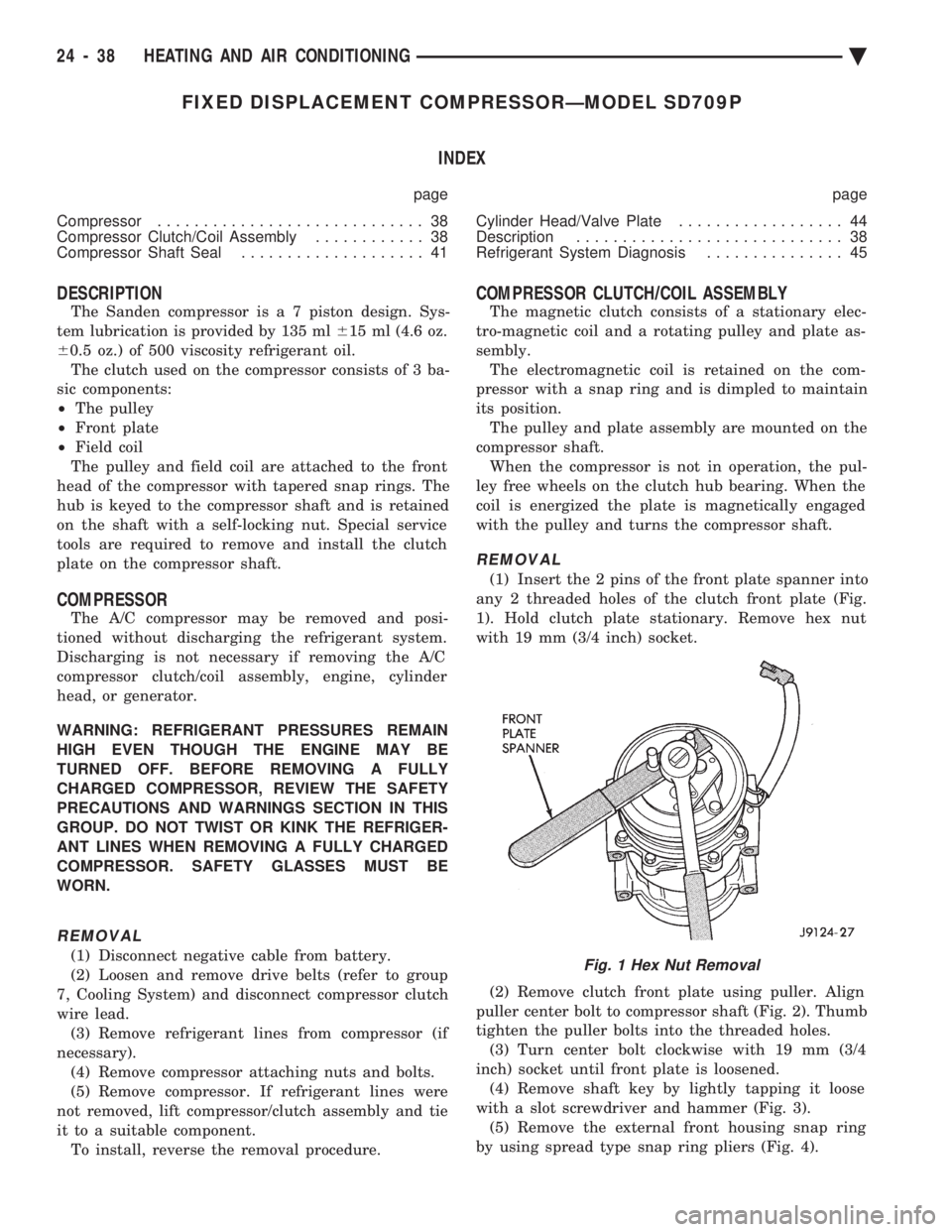
(1) Insert the 2 pins of the front plate spanner into
any 2 threaded holes of the clutch front plate (Fig.
1). Hold clutch plate stationary. Remove hex nut
with 19 mm (3/4 inch) socket.
(2) Remove clutch front plate using puller. Align
puller center bolt to compressor shaft (Fig. 2). Thumb
tighten the puller bolts into the threaded holes. (3) Turn center bolt clockwise with 19 mm (3/4
inch) socket until front plate is loosened. (4) Remove shaft key by lightly tapping it loose
with a slot screwdriver and hammer (Fig. 3). (5) Remove the external front housing snap ring
by using spread type snap ring pliers (Fig. 4).
Fig. 1 Hex Nut Removal
24 - 38 HEATING AND AIR CONDITIONING Ä
Page 2378 of 2438
Involves the wiring, blend-air door actuator, or the
ATC control head.
² DIAGNOSTIC TROUBLE CODES 3, 16, 17, 18, 19,
and 24 Involves the wiring, mode door actuator, or the ATC
control head.
² DIAGNOSTIC TROUBLE CODE 4
Involves the wiring, blend-air door actuator, mode
door actuator, fresh/recirc. door actuator, or the ATC
control head.
² DIAGNOSTIC TROUBLE CODE 5
Involves the wiring, fresh/recirc. door actuator, or the
ATC control head.
² DIAGNOSTIC TROUBLE CODE 6
Involves the compressor circuit signal wiring, or the
ATC control head.
² DIAGNOSTIC TROUBLE CODE 7
Involves the blower wiring, power module, or the
ATC control head.
² DIAGNOSTIC TROUBLE CODES 8, 21, 22
Requires replacing the ATC control head.
² DIAGNOSTIC TROUBLE CODES 9, and 27
Involves the wiring, sun sensor, or the ATC control
head.
² DIAGNOSTIC TROUBLE CODES 10, and 28
Involves the wiring, water temperature sensor, or the
ATC control head.
² DIAGNOSTIC TROUBLE CODES 11, and 25
Involves the wiring, ambient temperature sensor, or
the ATC control head.
² DIAGNOSTIC TROUBLE CODES 12, and 26
Involves the wiring, in-car temperature
sensor/aspirator, or the ATC control head.
DIAGNOSTIC TROUBLE CODE SERVICE PROCE-
DURES
The control keyboard will not function if pins
7, 9, 17, 19, or 20 of the 21-way wiring connector
are shorted to battery voltage. For electrical pin numbers, refer to the wiring Pin
out charts (Figs. 1, 2, 3, 4, 5, or 6).
DIAGNOSTIC TROUBLE CODE 1ÐOUTPUT FAILURE WITH ALL OUTPUTS LOW
(1) Remove pin #2 from 21-way connector on control
and retest system. If code 01 does not appear, the
control is good. Disconnect 21-way connector from control. With an
ohmmeter, measure the resistance between pin #2 and
pin #12 of 21-way. This should be between 2,600 and
2,800 ohms. If yes, the power module is good. Source of voltage on pin #2 is in the wiring. Repair
and retest system. (2) Remove pin #13 from 21-way connector on con-
trol and retest system. If code 01 does not appear, the
control is good. Locate source of voltage on pin #13.
Repair and retest system. (3) Remove pin #5 from 21-way connector on control
and retest system. If code 01 does not appear, the
control is good. Locate source of voltage on pin #5.
Repair and retest system. (4) Remove pin #6 from 21-way connector on control
and retest system. If code 01 does not appear, the
control is good. Locate source of voltage on pin #6.
Repair and retest system. (5) Remove pin #15 from 21-way connector on con-
trol and retest system. If code 01 does not appear, the
control is good. Locate source of voltage on pin #15.
Repair and retest system.
DIAGNOSTIC TROUBLE CODE 2ÐBLEND AC- TUATOR DRIVE SIGNAL NOT HIGH
If both Diagnostic Trouble Codes 2 and 3 occur
simultaneously, do both procedures. There is
typically only 1 failure. (1) Disconnect terminal #6 on the ATC control 21-
way connector and retest the system. Note that remov-
ing this terminal may generate additional Diagnostic
Trouble Codes. Disregard these at this time. (2) If Diagnostic Trouble Code 2 reappears, replace
control. (3) If code 2 does not reappear, the problem is a
shorted blend door actuator motor or a short to ground
in circuit 33 (pin #6). (4) Remove 21-way connector and check for continu-
ity from pin #6 to chassis ground. There should not be
any continuity. If continuity is there, repair wiring and
retest. (5) Check resistance across pins #6 and #4 of the
21-way for a shorted actuator motor. Resistance should
be between 20 and 50 ohms. If not correct, replace
actuator.
DIAGNOSTIC TROUBLE CODE 3ÐMODE AC- TUATOR DRIVE SIGNAL NOT HIGH
If both Diagnostic Trouble Codes 2 and 3 occur
simultaneously, do both procedures. There is
typically only 1 failure. (1) Disconnect terminal #5 on the ATC control 21-
way connector and retest the system. Removing this
terminal may generate additional Diagnostic Trouble
Codes. Disregard these at this time. (2) If Diagnostic Trouble Code 3 reappears, replace
control. (3) If code 3 does not reappear, the problem is a
shorted mode door actuator motor, or a short to ground
in circuit #35 (pin #5). (4) Remove 21-way and check for continuity from pin
#5 to chassis ground. There should not be any continu-
ity. If continuity is there, repair wiring and retest.
24 - 74 HEATING AND AIR CONDITIONING Ä