1993 CHEVROLET PLYMOUTH ACCLAIM key battery
[x] Cancel search: key batteryPage 1064 of 2438
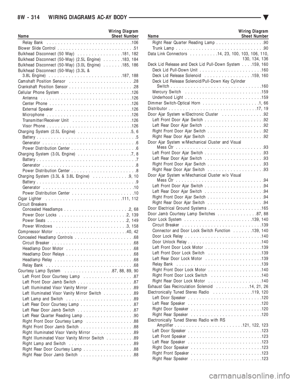
Wiring Diagram
Name Sheet Number
Relay Bank ............................. .106
Blower Slide Control ...........................51
Bulkhead Disconnect (50 Way) ................181, 182
Bulkhead Disconnect (50-Way) (2.5L Engine) .......183, 184
Bulkhead Disconnect (50-Way) (3.0L Engine) .......185, 186
Bulkhead Disconnect (50-Way) (3.3L & 3.8L Engine) ......................... .187, 188
Camshaft Position Sensor .......................28
Crankshaft Position Sensor .......................28
Cellular Phone System ........................ .126
Antenna ............................... .126
Center Phone ............................ .126
External Speaker .......................... .126
Microphone ............................. .126
Transmitter/Receiver Unit .................... .126
Visor Phone ............................. .126
Charging System (2.5L Engine) ...................5,6
Battery ...................................5
Generator .................................6
Power Distribution Center .......................6
Charging System (3.0L Engine) ...................7,8
Battery ...................................7
Generator .................................8
Power Distribution Center .......................8
Charging System (3.3L & 3.8L Engine) .............9,10
Battery ...................................9
Generator ................................10
Power Distribution Center ......................10
Cigar Lighter .......................... .111, 112
Circuit Breakers Concealed Headlamps .......................2,68
Power Door Locks ........................2,139
Power Seats ............................2,149
Power Windows .........................3,158
Compressor Motor ........................ .40, 42
Concealed Headlamp Controls .....................68
Circuit Breaker .............................68
Headlamp Door Motor ........................68
Headlamp Door Relays ........................68
Headlamp Relay ............................68
Relay Bank ...............................68
Courtesy Lamp System .................87, 88, 89, 90
Left Front Door Courtesy Lamp ..................87
Left Front Door Jamb Switch ....................87
Left Illuminated Visor Vanity Mirror ................89
Left Illuminated Visor Vanity Mirror Switch ...........89
Left Lamp and Switch ........................89
Left Rear Door Courtesy Lamp ...................87
Left Rear Door Jamb Switch ....................87
Left Rear Quarter Reading Lamp ..................90
Right Front Door Courtesy Lamp .................88
Right Front Door Jamb Switch ...................88
Right Illuminated Visor Vanity Mirror ...............89
Right Illuminated Visor Vanity Mirror Switch ..........89
Right Lamp and Switch .......................89
Right Rear Door Courtesy Lamp ..................88
Right Rear Door Jamb Switch ...................88Wiring Diagram
Name Sheet Number
Right Rear Quarter Reading Lamp .................90
Trunk Lamp ...............................90
Data Link Connectors ..........14, 23, 100, 103, 106, 110,
130, 134, 136
Deck Lid Release and Deck Lid Pull-Down System . . . .159, 160
Deck Lid Pull-Down Unit ..................... .160
Deck Lid Release Solenoid .................159, 160
Deck Lid Release Solenoid/Pull-Down Key Cylinder Switch ............................... .160
Mercury Switch .......................... .159
Underhood Light .......................... .159
Dimmer Switch-Optical Horn ....................1,66
Distributor .............................. .17, 19
Door Ajar System w/Electronic Cluster ...............92
Left Front Door Ajar Switch .....................92
Left Rear Door Ajar Switch .....................92
Right Front Door Ajar Switch ....................92
Right Rear Door Ajar Switch ....................92
Door Ajar System w/Mechanical Cluster and Visual Mess Ctr ...............................93
Left Front Door Ajar Switch .....................93
Left Rear Door Ajar Switch .....................93
Right Front Door Ajar Switch ....................93
Right Rear Door Ajar Switch ....................93
Door Ajar System w/Mechanical Cluster w/o Visual Mess Ctr ...............................94
Left Front Door Ajar Switch .....................94
Left Rear Door Ajar Switch .....................94
Right Front Door Ajar Switch ....................94
Right Rear Door Ajar Switch ....................94
Door Electrical Ground Systems ...................165
Door Jamb Courtesy Lamp Switches ..............87, 88
Door Lock System ....................... .139, 140
Circuit Breaker ........................... .139
Connector and Door Lock Switch Function .......139, 140
Door Lock Relay .......................... .140
Door Unlock Relay ......................... .140
Left Front Door Lock Motor ................... .139
Left Front Door Lock Switch ...................139
Left Rear Door Lock Motor ................... .139
Relay Bank ............................. .139
Right Front Door Lock Motor ...................140
Right Front Door Lock Switch ..................140
Right Rear Door Lock Motor ...................140
Exhaust Gas Recirculation Solenoid ............14, 21, 26
Electronically Tuned Stereo Radio ..............119, 120
Left Door Speaker ......................... .120
Left Rear Speaker ......................... .120
Right Door Speaker ........................ .120
Right Rear Speaker ........................ .120
Electronically Tuned Stereo Radio with RS Amplifier ....................... .121, 122, 123
Left Door Speaker ......................... .123
Left Front Speaker ......................... .123
Left Rear Speaker ......................... .123
Right Door Speaker ........................ .123
Right Front Speaker ........................ .123
Right Rear Speaker ........................ .123
8W - 314 WIRING DIAGRAMS AC-AY BODY Ä
Page 1286 of 2438
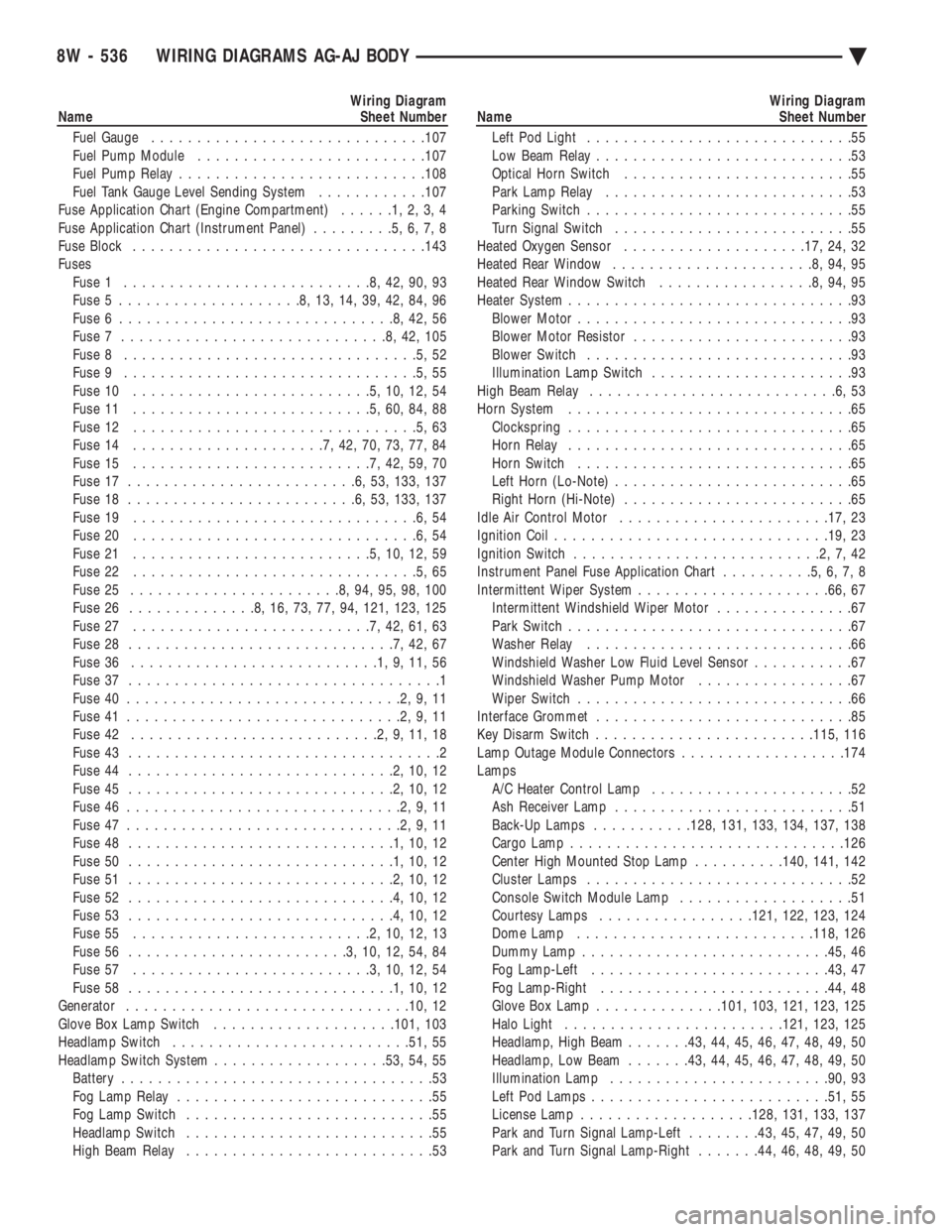
Wiring Diagram
Name Sheet Number
Fuel Gauge ............................. .107
Fuel Pump Module ........................ .107
Fuel Pump Relay .......................... .108
Fuel Tank Gauge Level Sending System ............107
Fuse Application Chart (Engine Compartment) ......1,2,3,4
Fuse Application Chart (Instrument Panel) .........5,6,7,8
Fuse Block ............................... .143
Fuses Fuse 1 ...........................8,42,90,93
Fuse 5 ....................8,13,14,39,42,84,96
Fuse 6 ..............................8,42,56
Fuse 7 .............................8,42,105
Fuse 8 ................................5,52
Fuse 9 ................................5,55
Fuse 10 ..........................5,10,12,54
Fuse 11 ..........................5,60,84,88
Fuse 12 ...............................5,63
Fuse 14 .....................7,42,70,73,77,84
Fuse 15 ..........................7,42,59,70
Fuse 17 .........................6,53, 133, 137
Fuse 18 .........................6,53, 133, 137
Fuse 19 ...............................6,54
Fuse 20 ...............................6,54
Fuse 21 ..........................5,10,12,59
Fuse 22 ...............................5,65
Fuse 25 .......................8,94,95,98,100
Fuse 26 ..............8,16,73,77,94, 121, 123, 125
Fuse 27 ..........................7,42,61,63
Fuse 28 .............................7,42,67
Fuse 36 ...........................1,9,11,56
Fuse 37 ..................................1
Fuse 40 ..............................2,9,11
Fuse 41 ..............................2,9,11
Fuse 42 ...........................2,9,11,18
Fuse 43 ..................................2
Fuse 44 .............................2,10,12
Fuse 45 .............................2,10,12
Fuse 46 ..............................2,9,11
Fuse 47 ..............................2,9,11
Fuse 48 .............................1,10,12
Fuse 50 .............................1,10,12
Fuse 51 .............................2,10,12
Fuse 52 .............................4,10,12
Fuse 53 .............................4,10,12
Fuse 55 ..........................2,10,12,13
Fuse 56 ........................3,10,12,54,84
Fuse 57 ..........................3,10,12,54
Fuse 58 .............................1,10,12
Generator .............................. .10, 12
Glove Box Lamp Switch ................... .101, 103
Headlamp Switch ......................... .51, 55
Headlamp Switch System .................. .53, 54, 55
Battery ..................................53
Fog Lamp Relay ............................55
Fog Lamp Switch ...........................55
Headlamp Switch ...........................55
High Beam Relay ...........................53Wiring Diagram
Name Sheet Number
Left Pod Light .............................55
Low Beam Relay ............................53
Optical Horn Switch .........................55
Park Lamp Relay ...........................53
Parking Switch .............................55
Turn Signal Switch ..........................55
Heated Oxygen Sensor ................... .17, 24, 32
Heated Rear Window ......................8,94,95
Heated Rear Window Switch .................8,94,95
Heater System ...............................93
Blower Motor ..............................93
Blower Motor Resistor ........................93
Blower Switch .............................93
Illumination Lamp Switch ......................93
High Beam Relay ...........................6,53
Horn System ...............................65
Clockspring ...............................65
Horn Relay ...............................65
Horn Switch ..............................65
Left Horn (Lo-Note) ..........................65
Right Horn (Hi-Note) .........................65
Idle Air Control Motor ...................... .17, 23
Ignition Coil ............................. .19, 23
Ignition Switch ...........................2,7,42
Instrument Panel Fuse Application Chart ..........5,6,7,8
Intermittent Wiper System .................... .66, 67
Intermittent Windshield Wiper Motor ...............67
Park Switch ...............................67
Washer Relay .............................66
Windshield Washer Low Fluid Level Sensor ...........67
Windshield Washer Pump Motor .................67
Wiper Switch ..............................66
Interface Grommet ............................85
Key Disarm Switch ....................... .115, 116
Lamp Outage Module Connectors ..................174
Lamps A/C Heater Control Lamp ......................52
Ash Receiver Lamp ..........................51
Back-Up Lamps ...........128, 131, 133, 134, 137, 138
Cargo Lamp ............................. .126
Center High Mounted Stop Lamp ..........140, 141, 142
Cluster Lamps .............................52
Console Switch Module Lamp ...................51
Courtesy Lamps ................ .121, 122, 123, 124
Dome Lamp ......................... .118, 126
Dummy Lamp .......................... .45, 46
Fog Lamp-Left ......................... .43, 47
Fog Lamp-Right ........................ .44, 48
Glove Box Lamp ............. .101, 103, 121, 123, 125
Halo Light ....................... .121, 123, 125
Headlamp, High Beam .......43, 44, 45, 46, 47, 48, 49, 50
Headlamp, Low Beam .......43, 44, 45, 46, 47, 48, 49, 50
Illumination Lamp ....................... .90, 93
Left Pod Lamps ......................... .51, 55
License Lamp .................. .128, 131, 133, 137
Park and Turn Signal Lamp-Left ........43, 45, 47, 49, 50
Park and Turn Signal Lamp-Right .......44, 46, 48, 49, 50
8W - 536 WIRING DIAGRAMS AG-AJ BODY Ä
Page 1467 of 2438
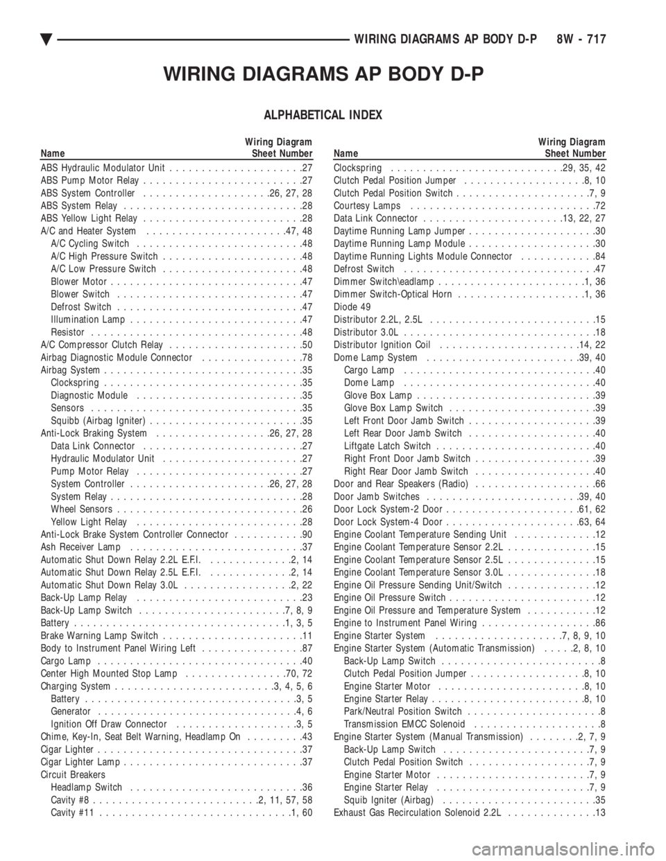
WIRING DIAGRAMS AP BODY D-P
ALPHABETICAL INDEX
Wiring Diagram
Name Sheet Number
ABS Hydraulic Modulator Unit .....................27
ABS Pump Motor Relay .........................27
ABS System Controller ................... .26, 27, 28
ABS System Relay ............................28
ABS Yellow Light Relay .........................28
A/C and Heater System ..................... .47, 48
A/C Cycling Switch ..........................48
A/C High Pressure Switch ......................48
A/C Low Pressure Switch ......................48
Blower Motor ..............................47
Blower Switch .............................47
Defrost Switch .............................47
Illumination Lamp ...........................47
Resistor .................................48
A/C Compressor Clutch Relay .....................50
Airbag Diagnostic Module Connector ................78
Airbag System ...............................35
Clockspring ...............................35
Diagnostic Module ..........................35
Sensors .................................35
Squibb (Airbag Igniter) ........................35
Anti-Lock Braking System ..................26, 27, 28
Data Link Connector .........................27
Hydraulic Modulator Unit ......................27
Pump Motor Relay ..........................27
System Controller ..................... .26, 27, 28
System Relay ..............................28
Wheel Sensors .............................26
Yellow Light Relay ..........................28
Anti-Lock Brake System Controller Connector ...........90
Ash Receiver Lamp ...........................37
Automatic Shut Down Relay 2.2L E.F.I. .............2,14
Automatic Shut Down Relay 2.5L E.F.I. .............2,14
Automatic Shut Down Relay 3.0L .................2,22
Back-Up Lamp Relay ..........................23
Back-Up Lamp Switch .......................7,8,9
Battery .................................1,3,5
Brake Warning Lamp Switch ......................11
Body to Instrument Panel Wiring Left ................87
Cargo Lamp ................................40
Center High Mounted Stop Lamp ................70, 72
Charging System .........................3,4,5,6
Battery .................................3,5
Generator ...............................4,6
Ignition Off Draw Connector ...................3,5
Chime, Key-In, Seat Belt Warning, Headlamp On .........43
Cigar Lighter ................................37
Cigar Lighter Lamp ............................37
Circuit Breakers Headlamp Switch ...........................36
Cavity #8 ..........................2,11,57,58
Cavity #11 ..............................1,60Wiring Diagram
Name Sheet Number
Clockspring .......................... .29, 35, 42
Clutch Pedal Position Jumper ...................8,10
Clutch Pedal Position Switch .....................7,9
Courtesy Lamps .............................72
Data Link Connector ..................... .13, 22, 27
Daytime Running Lamp Jumper ....................30
Daytime Running Lamp Module ....................30
Daytime Running Lights Module Connector ............84
Defrost Switch ..............................47
Dimmer Switch\eadlamp .......................1,36
Dimmer Switch-Optical Horn ....................1,36
Diode 49
Distributor 2.2L, 2.5L ..........................15
Distributor 3.0L ..............................18
Distributor Ignition Coil ..................... .14, 22
Dome Lamp System ....................... .39, 40
Cargo Lamp ..............................40
Dome Lamp ..............................40
Glove Box Lamp ............................39
Glove Box Lamp Switch .......................39
Left Front Door Jamb Switch ....................39
Left Rear Door Jamb Switch ....................40
Liftgate Latch Switch .........................40
Right Front Door Jamb Switch ...................39
Right Rear Door Jamb Switch ...................40
Door and Rear Speakers (Radio) ...................66
Door Jamb Switches ....................... .39, 40
Door Lock System-2 Door .................... .61, 62
Door Lock System-4 Door .................... .63, 64
Engine Coolant Temperature Sending Unit .............12
Engine Coolant Temperature Sensor 2.2L ..............15
Engine Coolant Temperature Sensor 2.5L ..............15
Engine Coolant Temperature Sensor 3.0L ..............18
Engine Oil Pressure Sending Unit/Switch ..............12
Engine Oil Pressure Switch .......................12
Engine Oil Pressure and Temperature System ...........12
Engine to Instrument Panel Wiring ..................86
Engine Starter System ....................7,8,9,10
Engine Starter System (Automatic Transmission) .....2,8,10
Back-Up Lamp Switch .........................8
Clutch Pedal Position Jumper ..................8,10
Engine Starter Motor .......................8,10
Engine Starter Relay ........................8,10
Park/Neutral Position Switch .....................8
Transmission EMCC Solenoid ....................8
Engine Starter System (Manual Transmission) ........2,7,9
Back-Up Lamp Switch .......................7,9
Clutch Pedal Position Switch ...................7,9
Engine Starter Motor ........................7,9
Engine Starter Relay ........................7,9
Squib Igniter (Airbag) ........................35
Exhaust Gas Recirculation Solenoid 2.2L ..............13
Ä WIRING DIAGRAMS AP BODY D-P 8W - 717
Page 1744 of 2438
INSTRUMENT PANEL CLUSTER IDENTIFICATIONÐFLEXIBLE FUEL AA-BODY
Flexible fuel A-Body vehicles use a unique gauge
cluster. To identify the cluster, remove it from the
instrument panel and check the number on the tag
on the top. If the part number matches the number
in the parts book for flexible fuel A-bodies, the vehi-
cle was built with the correct cluster. Refer to Group
8E, Instrument Panel and Gauges, for cluster re-
moval and installation.
METHANOL CONCENTRATION SENSORÐFLEXIBLE
FUEL AA-BODY
The methanol concentration sensor contains a mi-
croprocessor that determines the percentage of gaso-
line and methanol in the fuel system. From the
methanol concentration sensor input, the powertrain
control module (PCM) determines the amount of
methanol in the fuel. The vehicle can operate on a
mixtures up to 85 percent methanol, 15 percent gas-
oline. The methanol concentration sensor output voltages
varies with the percent of methanol in the fuel sys-
tem. The sensor output voltage (input for PCM)
ranges from 0.5 volts for pure gasoline to 4.75 volts
for 85 percent methanol. For two seconds at key ON
when the operator starts the vehicle, the sensor cal-
ibrates the PCM. During the calibration period the
sensor sends 4.45 volts to the PCM as a correction
factor. The methanol concentration sensor has a built-in
shutdown capability. If the sensor shuts down, it de-
faults to the previous learned value (output voltage
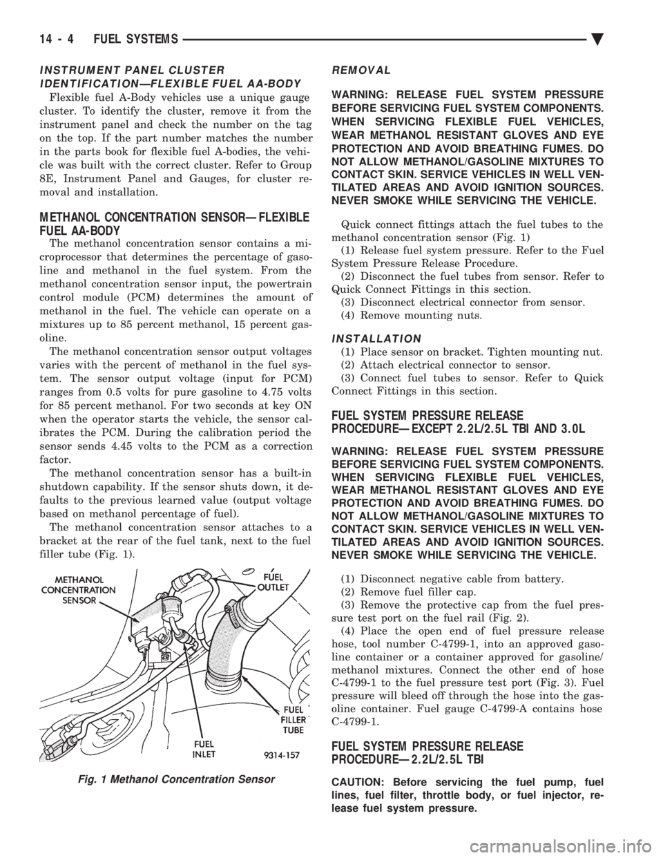
based on methanol percentage of fuel). The methanol concentration sensor attaches to a
bracket at the rear of the fuel tank, next to the fuel
filler tube (Fig. 1).
REMOVAL
WARNING: RELEASE FUEL SYSTEM PRESSURE
BEFORE SERVICING FUEL SYSTEM COMPONENTS.
WHEN SERVICING FLEXIBLE FUEL VEHICLES,
WEAR METHANOL RESISTANT GLOVES AND EYE
PROTECTION AND AVOID BREATHING FUMES. DO
NOT ALLOW METHANOL/GASOLINE MIXTURES TO
CONTACT SKIN. SERVICE VEHICLES IN WELL VEN-
TILATED AREAS AND AVOID IGNITION SOURCES.
NEVER SMOKE WHILE SERVICING THE VEHICLE.
Quick connect fittings attach the fuel tubes to the
methanol concentration sensor (Fig. 1) (1) Release fuel system pressure. Refer to the Fuel
System Pressure Release Procedure. (2) Disconnect the fuel tubes from sensor. Refer to
Quick Connect Fittings in this section. (3) Disconnect electrical connector from sensor.
(4) Remove mounting nuts.
INSTALLATION
(1) Place sensor on bracket. Tighten mounting nut.
(2) Attach electrical connector to sensor.
(3) Connect fuel tubes to sensor. Refer to Quick
Connect Fittings in this section.
FUEL SYSTEM PRESSURE RELEASE
PROCEDUREÐEXCEPT 2.2L/2.5L TBI AND 3.0L
WARNING: RELEASE FUEL SYSTEM PRESSURE
BEFORE SERVICING FUEL SYSTEM COMPONENTS.
WHEN SERVICING FLEXIBLE FUEL VEHICLES,
WEAR METHANOL RESISTANT GLOVES AND EYE
PROTECTION AND AVOID BREATHING FUMES. DO
NOT ALLOW METHANOL/GASOLINE MIXTURES TO
CONTACT SKIN. SERVICE VEHICLES IN WELL VEN-
TILATED AREAS AND AVOID IGNITION SOURCES.
NEVER SMOKE WHILE SERVICING THE VEHICLE.
(1) Disconnect negative cable from battery.
(2) Remove fuel filler cap.
(3) Remove the protective cap from the fuel pres-
sure test port on the fuel rail (Fig. 2). (4) Place the open end of fuel pressure release
hose, tool number C-4799-1, into an approved gaso-
line container or a container approved for gasoline/
methanol mixtures. Connect the other end of hose
C-4799-1 to the fuel pressure test port (Fig. 3). Fuel
pressure will bleed off through the hose into the gas-
oline container. Fuel gauge C-4799-A contains hose
C-4799-1.
FUEL SYSTEM PRESSURE RELEASE
PROCEDUREÐ2.2L/2.5L TBI
CAUTION: Before servicing the fuel pump, fuel
lines, fuel filter, throttle body, or fuel injector, re-
lease fuel system pressure.Fig. 1 Methanol Concentration Sensor
14 - 4 FUEL SYSTEMS Ä
Page 1770 of 2438
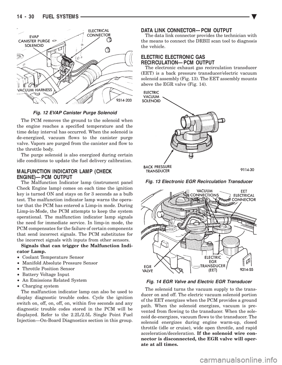
The PCM removes the ground to the solenoid when
the engine reaches a specified temperature and the
time delay interval has occurred. When the solenoid is
de-energized, vacuum flows to the canister purge
valve. Vapors are purged from the canister and flow to
the throttle body. The purge solenoid is also energized during certain
idle conditions to update the fuel delivery calibration.
MALFUNCTION INDICATOR LAMP (CHECK
ENGINE)ÐPCM OUTPUT
The Malfunction Indicator lamp (instrument panel
Check Engine lamp) comes on each time the ignition
key is turned ON and stays on for 3 seconds as a bulb
test. The malfunction indicator lamp warns the opera-
tor that the PCM has entered a Limp-in mode. During
Limp-in-Mode, the PCM attempts to keep the system
operational. The malfunction indicator lamp signals
the need for immediate service. In limp-in mode, the
PCM compensates for the failure of certain components
that send incorrect signals. The PCM substitutes for
the incorrect signals with inputs from other sensors. Signals that can trigger the Malfunction Indi-
cator Lamp.
² Coolant Temperature Sensor
² Manifold Absolute Pressure Sensor
² Throttle Position Sensor
² Battery Voltage Input
² An Emissions Related System
² Charging system
The malfunction indicator lamp can also be used to
display diagnostic trouble codes. Cycle the ignition
switch on, off, on, off, on, within five seconds and any
diagnostic trouble codes stored in the PCM will be
displayed. Refer to the 2.2L/2.5L Single Point Fuel
InjectionÐOn-Board Diagnostics section in this group.
DATA LINK CONNECTORÐPCM OUTPUT
The data link connector provides the technician with
the means to connect the DRBII scan tool to diagnosis
the vehicle.
ELECTRIC ELECTRONIC GAS
RECIRCULATIONÐPCM OUTPUT
The electronic exhaust gas recirculation transducer
(EET) is a back pressure transducer/electric vacuum
solenoid assembly (Fig. 13). The EET assembly mounts
above the EGR valve (Fig. 14).
The solenoid turns the vacuum supply to the trans-
ducer on and off. The electric vacuum solenoid portion
of the EET energizes when the PCM provides a ground
path. When the solenoid energizes, vacuum is pre-
vented from flowing to the transducer. When the sole-
noid de-energizes, vacuum flows to the transducer. The
solenoid energizes during engine warm-up, closed
throttle (idle or cruise), wide open throttle, and rapid
acceleration/deceleration. If the solenoid wire con-
nector is disconnected, the EGR valve will oper-
ate at all times.
Fig. 12 EVAP Canister Purge Solenoid
Fig. 13 Electronic EGR Recirculation Transducer
Fig. 14 EGR Valve and Electric EGR Transducer
14 - 30 FUEL SYSTEMS Ä
Page 1772 of 2438
TACHOMETERÐPCM OUTPUT
The PCM supplies engine RPM to the instrument
panel tachometer. Refer to Group 8 for tachometer
information.
MODES OF OPERATION
As input signals to the PCM change, the PCM
adjusts its response to the output devices. For example,
the PCM must calculate a different injector pulse
width and ignition timing for idle than it does for wide
open throttle (WOT). There are several different modes
of operation that determine how the PCM responds to
the various input signals. There are two different areas of operation, OPEN
LOOP and CLOSED LOOP. During OPEN LOOP modes, the PCM receives input
signals and responds according to preset PCM pro-
gramming. Input from the oxygen (O
2) sensor is not
monitored during OPEN LOOP modes. During CLOSED LOOP modes, the PCM does moni-
tor the oxygen (O
2) sensor input. This input tells the
PCM if the calculated injector pulse width results in an
air-fuel ratio of 14.7 to 1. By monitoring the exhaust
oxygen content, the can PCM fine tune injector pulse
width for optimum fuel economy and low emissions. The single point fuel injection system has the follow-
ing modes of operation:
² Ignition switch ON - Zero RPM
² Engine start-up
² Engine warm-up
² Cruise (Idle)
² Acceleration
² Deceleration
² Wide Open Throttle
² Ignition switch OFF
The engine start-up (cranking), engine warm-up, and
wide open throttle modes are OPEN LOOP modes. The
acceleration, deceleration, and cruise modes, with the
engine at operating temperature are CLOSED
LOOP modes (under most operating conditions).
IGNITION SWITCH ON (ZERO RPM) MODE
When the single point fuel injection system is acti-
vated by the ignition switch, the following actions
occur:
² The PCM determines atmospheric air pressure from
the MAP sensor input to calculate basic fuel strategy.
² The PCM monitors the coolant temperature sensor
and throttle position sensor inputs. The PCM modifies
fuel strategy based on these inputs. When the key is in the ON position and the engine is
not running, the (ASD) and fuel pump relays are not
energized. Therefore, battery voltage is not supplied to
the fuel pump, ignition coil, fuel injector or oxygen
sensor heating element. ENGINE START-UP MODE
This is an OPEN LOOP mode. The following actions
occur when the starter motor is engaged. If the PCM receives a distributor signal it energizes
the auto shutdown (ASD) relay and fuel pump relay to
supply battery voltage to the fuel injector, ignition coil
and oxygen sensor heating element. If the PCM does
not receive a distributor input, it de-energizes the ASD
and fuel pump relays after approximately one second. When the engine idles within 664 RPM of the target
RPM, the PCM compares the current MAP value with
the atmospheric pressure value it received during the
Ignition Switch On (Zero RPM) Mode. If a minimum
difference between the two is not detected, a MAP
sensor fault is set into memory. Once the ASD relay and fuel pump relay have ener-
gized, the PCM:
² Supplies a ground path to the injector. The injector
is pulsed four times per engine revolution instead of
the normal two pulses per revolution.
² Determines injector pulse width based on coolant
temperature, MAP sensor input, throttle position, and
the number of engine revolutions since cranking was
initiated.
² Monitors the coolant temperature sensor, distribu-
tor pick-up, MAP sensor, and throttle position sensor to
determine correct ignition timing.
ENGINE WARM-UP MODE
This is a OPEN LOOP mode. The following inputs
are received by the PCM:
² coolant temperature
² manifold absolute pressure (MAP)
² engine speed (distributor pick-up)
² throttle position
² A/C switch
² battery voltage
The PCM provides a ground path for the injector to
precisely control injector pulse width (by switching the
ground on and off) and fires the injector twice per
engine revolution. The PCM regulates ignition timing.
It also adjusts engine idle speed through the idle air
control motor.
CRUISE OR IDLE MODE
When the engine is at operating temperature this is
a CLOSED LOOP mode. During cruising speed and at
idle the following inputs are received by the PCM:
² coolant temperature
² manifold absolute pressure
² engine speed
² throttle position
² exhaust gas oxygen content
² A/C control positions
² battery voltage
14 - 32 FUEL SYSTEMS Ä
Page 1785 of 2438
SYSTEMS TEST
WARNING: APPLY PARKING BRAKE AND/OR
BLOCK WHEELS BEFORE PERFORMING A TEST
WITH THE ENGINE OPERATING.
OBTAINING DIAGNOSTIC TROUBLE CODES
(1) Connect DRBII scan tool to the data link con-
nector located in the engine compartment near the
powertrain control module (PCM). (2) Start the engine if possible, cycle the transaxle
selector and the A/Cswitch if applicable. Shut off
the engine. (3) Turn the ignition switch on, access Read Fault
Screen. Record all the fault messages shown on the
DRBII scan tool. Observe the malfunction indicator
lamp (check engine lamp on the instrument panel).
The lamp should light for 3 seconds then go out (bulb
check).
STATE DISPLAY TEST MODE
The switch inputs used by the powertrain control
module (PCM) have only two recognized states,
HIGH and LOW. For this reason, the PCM cannot
recognize the difference between a selected switch po-
sition versus an open circuit, a short circuit, or a de-
fective switch. If the change is displayed, it can be
assumed that the entire switch circuit to the PCM is
functional. From the state display screen access ei-
ther State Display Inputs and Outputs or State Dis-
play Sensors.
STATE DISPLAY INPUTS AND OUTPUTS
Connect the DRBII scan tool to the vehicle and ac-
cess the State Display screen. Then access Inputs and
Outputs. The following is a list of the engine control
system functions accessible through the Inputs and
Outputs screen. Park/Neutral Switch (automatic transaxle only)
Speed Control Resume
Brake Switch
Speed Control On/Off
Speed Control Set
A/C Switch Sense
S/C (Speed Control) Vent Solenoid
S/C (Speed Control) Vacuum Solenoid
Torque Converter Clutch Solenoid (3 speed auto-
matic transaxle)
A/C Clutch Relay
EGR Solenoid
Auto Shutdown Relay
Radiator Fan Relay
Purge Solenoid
Malfunction Indicator (Check Engine) Lamp
STATE DISPLAY SENSORS
Connect the DRBII scan tool to the vehicle and ac-
cess the State Display screen. Then access Sensor
Display. The following is a list of the engine control
system functions accessible through the Sensor Dis-
play screen. Oxygen Sensor Signal
Coolant Temperature
Coolant Temp Sensor
Throttle Position
Minimum Throttle
Battery Voltage
MAP Sensor Reading
Idle Air Control Motor Position
Added Adaptive Fuel
Adaptive Fuel Factor
Barometric Pressure
Min Airflow Idl Spd
Engine Speed
Fault #1 Key-On Info
Module Spark Advance
Speed Control Target
Fault #2 Key-On Info
Fault #3 Key-On Info
Speed Control Status
Charging System Goal
Theft Alarm Status
Speed Control Switch Voltage
Map Sensor Voltage
Vehicle Speed
Oxygen Sensor State
MAP Gauge Reading
Throttle Opening (percentage)
Total Spark Advance
CIRCUIT ACTUATION TEST MODE
The circuit actuation test mode checks for proper
operation of output circuits or devices which the pow-
ertrain control module (PCM) cannot internally rec-
ognize. The PCM can attempt to activate these
outputs and allow an observer to verify proper oper-
ation. Most of the tests provide an audible or visual
indication of device operation (click of relay contacts,
spray fuel, etc.). With the exception of an intermit-
tent condition, if a device functions properly during
its test, it can be assumed that the device, its associ-
ated wiring, and its driver circuit are in working or-
der.
OBTAINING CIRCUIT ACTUATION TEST
Connect the DRBII scan tool to the vehicle and ac-
cess the Actuators screen. The following is a list of
the engine control system functions accessible
through Actuators screens. Stop All Tests
Ignition Coil #1
Fuel Injector #1
Idle Air Control Motor Open/Close
Ä FUEL SYSTEMS 14 - 45
Page 1790 of 2438
(5) Remove throttle cable. If equipped, remove the
speed control and transaxle kickdown cables. (6) Remove return spring.
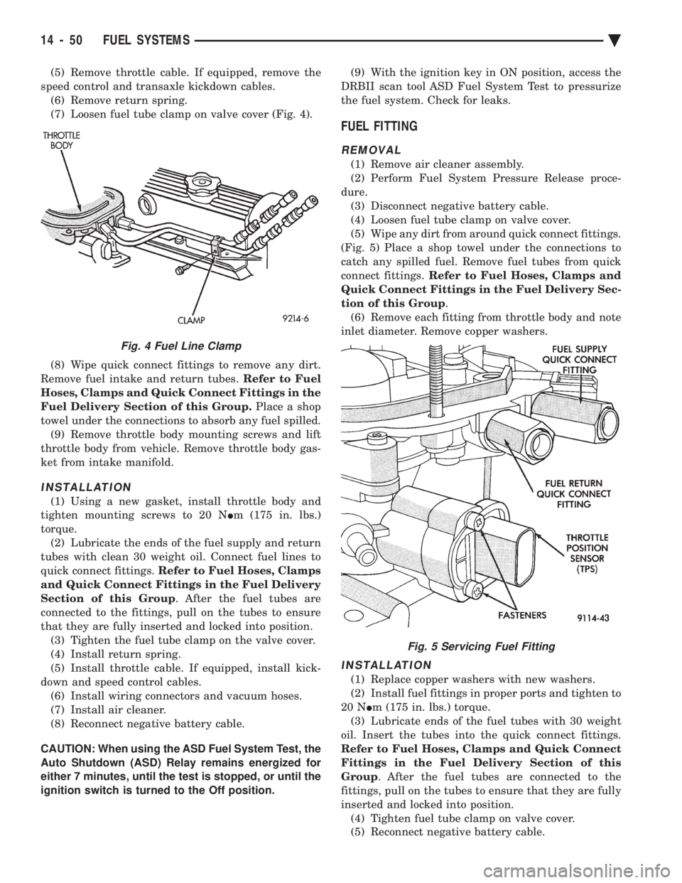
(7) Loosen fuel tube clamp on valve cover (Fig. 4).
(8) Wipe quick connect fittings to remove any dirt.
Remove fuel intake and return tubes. Refer to Fuel
Hoses, Clamps and Quick Connect Fittings in the
Fuel Delivery Section of this Group. Place a shop
towel under the connections to absorb any fuel spilled. (9) Remove throttle body mounting screws and lift
throttle body from vehicle. Remove throttle body gas-
ket from intake manifold.
INSTALLATION
(1) Using a new gasket, install throttle body and
tighten mounting screws to 20 N Im (175 in. lbs.)
torque. (2) Lubricate the ends of the fuel supply and return
tubes with clean 30 weight oil. Connect fuel lines to
quick connect fittings. Refer to Fuel Hoses, Clamps
and Quick Connect Fittings in the Fuel Delivery
Section of this Group . After the fuel tubes are
connected to the fittings, pull on the tubes to ensure
that they are fully inserted and locked into position. (3) Tighten the fuel tube clamp on the valve cover.
(4) Install return spring.
(5) Install throttle cable. If equipped, install kick-
down and speed control cables. (6) Install wiring connectors and vacuum hoses.
(7) Install air cleaner.
(8) Reconnect negative battery cable.
CAUTION: When using the ASD Fuel System Test, the
Auto Shutdown (ASD) Relay remains energized for
either 7 minutes, until the test is stopped, or until the
ignition switch is turned to the Off position. (9) With the ignition key in ON position, access the
DRBII scan tool ASD Fuel System Test to pressurize
the fuel system. Check for leaks.
FUEL FITTING
REMOVAL
(1) Remove air cleaner assembly.
(2) Perform Fuel System Pressure Release proce-
dure. (3) Disconnect negative battery cable.
(4) Loosen fuel tube clamp on valve cover.
(5) Wipe any dirt from around quick connect fittings.
(Fig. 5) Place a shop towel under the connections to
catch any spilled fuel. Remove fuel tubes from quick
connect fittings. Refer to Fuel Hoses, Clamps and
Quick Connect Fittings in the Fuel Delivery Sec-
tion of this Group .
(6) Remove each fitting from throttle body and note
inlet diameter. Remove copper washers.
INSTALLATION
(1) Replace copper washers with new washers.
(2) Install fuel fittings in proper ports and tighten to
20 N Im (175 in. lbs.) torque.
(3) Lubricate ends of the fuel tubes with 30 weight
oil. Insert the tubes into the quick connect fittings.
Refer to Fuel Hoses, Clamps and Quick Connect
Fittings in the Fuel Delivery Section of this
Group . After the fuel tubes are connected to the
fittings, pull on the tubes to ensure that they are fully
inserted and locked into position. (4) Tighten fuel tube clamp on valve cover.
(5) Reconnect negative battery cable.
Fig. 5 Servicing Fuel Fitting
Fig. 4 Fuel Line Clamp
14 - 50 FUEL SYSTEMS Ä