1993 CHEVROLET PLYMOUTH ACCLAIM light
[x] Cancel search: lightPage 698 of 2438
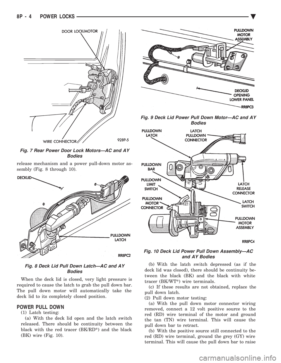
release mechanism and a power pull-down motor as-
sembly (Fig. 8 through 10). When the deck lid is closed, very light pressure is
required to cause the latch to grab the pull down bar.
The pull down motor will automatically take the
deck lid to its completely closed position.
POWER PULL DOWN
(1) Latch testing: (a) With the deck lid open and the latch switch
released. There should be continuity between the
black with the red tracer (BK/RD*) and the black
(BK) wire (Fig. 10). (b) With the latch switch depressed (as if the
deck lid was closed), there should be continuity be-
tween the black (BK) and the black with white
tracer (BK/WT*) wire terminals. (c) If these results are not obtained, replace the
pull down latch.
(2) Pull down motor testing: (a) With the pull down motor connector wiring
removed, connect a 12 volt positive source to the
red (RD) wire terminal of the motor and ground
the tan (TN) wire terminal. This will cause the
pull down bar to retract. (b) With the positive source still connected to the
red (RD) wire terminal, ground the grey (GY) wire
terminal. This will cause the pull down bar to raise
Fig. 7 Rear Power Door Lock MotorsÐAC and AY Bodies
Fig. 8 Deck Lid Pull Down LatchÐAC and AYBodies
Fig. 9 Deck Lid Power Pull Down MotorÐAC and AY Bodies
Fig. 10 Deck Lid Power Pull Down AssemblyÐACand AY Bodies
8P - 4 POWER LOCKS Ä
Page 707 of 2438

POWER SEATS
CONTENTS
page page
ADJUSTER ............................. 3
CIRCUIT BREAKER TEST .................. 1
ENTHUSIAST SEAT ....................... 4
GENERAL INFORMATION .................. 1
HARNESS VOLTAGE TEST ................. 1
HORIZONTAL AND VERTICAL TRANSMISSIONS ....................... 3
MEMORY CONTROL MODULE REPLACEMENT ....................... 19
MOTOR ................................ 3
MOTOR TESTS .......................... 1
POWER MEMORY SEAT, RECLINER AND MIRRORS ............................. 5 POWER MEMORY SEAT, RECLINER AND
MIRRORS DIAGNOSIS ................... 9
POWER RECLINER MECHANISM ........... 18
POWER RECLINER MOTOR AND CABLE ..... 17
RECLINER SWITCH REPLACEMENT ......... 19
RECLINER SWITCH TEST ................. 19
SEAT ASSEMBLY ........................ 3
SWITCH REPLACEMENT REMOVAL .......... 5
SWITCH TEST ........................... 5
SWITCH TEST ........................... 3
TEST PROCEDURES ...................... 6
TEST PROCEDURES ...................... 1
GENERAL INFORMATION
Power seats can be adjusted in six different direc-
tions up, down, forward, back, tilt forward, or tilt
rearward. A three armature permanent magnet reversible mo-
tor is coupled through cables to worm gear box assem-
blies located in the seat tracks, providing the various
seat movements. The electrical circuit is protected by a 30 amp circuit
breaker located on the fuse block.
TEST PROCEDURES
Before any testing is attempted the battery should be
carefully charged and all connections and terminals
cleaned and tightened to insure proper continuity and
grounds. With dome lamp on, apply switch in direction of
failure. If dome lamp dims the seat motor is trying to
work indicating mechanical jamming. If dome lamp
does not dim, then proceed with the following electrical
tests.
CIRCUIT BREAKER TEST
Find correct circuit breaker on fuse block. Pull out
slightly but be sure that circuit breaker terminals still
contact terminals in fuse block. Connect ground wire of
voltmeter to a good ground. With probe of voltmeter
positive wire, check both terminals of circuit breaker
for battery voltage. If only one terminal checks at
battery voltage, circuit breaker is defective and must
be replaced. If neither terminal shows battery voltage,
check for open or shorted circuit to circuit breaker.
HARNESS VOLTAGE TEST
The following test will determine whether or not
voltage is continuous through the body harness to the
switch. (1) Remove power seat switch from mounting posi-
tion and disconnect switch from wiring harness. (2) Connect one lead of test light to ground terminal,
black wire (BK) of center section, and touch other test
light lead to red wire (RD) terminal. (3) If test light comes on, harness to switch is good.
If test light does not come on, perform circuit breaker
test.
MOTOR TESTS
AA BODY
(1) Remove switch from mounting position and dis-
connect from harness. (2) To check the center motor, connect a jumper wire
between pin 5 and pin 3 (Fig. 1). Connect a second
jumper wire between pin 7 and pin 4 If motor does not
operate, reverse the jumpers, pin 5 to pin 4 and pin 7 to
pin 3. If motor still does not operate check wiring
between switch connector and motor assembly. If wir-
ing checks good replace motor assembly. (3) To check the front motor, connect a jumper wire
between pin 5 and pin 1 (Fig. 1). Connect a second
jumper wire between pin 7 and pin 8. If motor does not
operate, reverse the jumpers, pin 5 to pin 8 and pin 7 to
pin 1. If motor still does not operate check wiring
between switch connector and motor assembly. If wir-
ing checks good replace motor assembly.
(4) To check the rear motor, connect a covered jumper
wire between pin 5 and pin 6 (Fig. 1). Connect a second
Ä POWER SEATS 8R - 1
Page 727 of 2438
POWER WINDOWS
CONTENTS
page page
BENCH REPAIR OF REGULATOR AND MOTOR CONVENTIONAL REGULATORS .......... 5
GEAR AND PINION REPLACEMENT AND LUBRICATION ....................... 3
GENERAL INFORMATION .................. 1
MOTOR REPLACEMENT ................... 7
MOTOR REPLACEMENT CONVENTIONAL REGULATORS ....................... 3
MOTOR REPLACEMENTÐFLEX DRIVE REGULATORS ......................... 5 POWER WINDOW CABLE HOUSING/MOTOR RE-
PLACEMENTÐAC and AY BODIES ........ 7
QUARTER WINDOW MOTOR REPLACEMENTÐ AJ BODY ............................. 9
QUARTER WINDOW REPLACEMENTÐ AJ BODY ............................. 8
WINDOW LIFT MOTOR TEST .............. 1
WINDOW LIFT SWITCH TEST .............. 1
WIRING VOLTAGE TEST .................. 1
GENERAL INFORMATION
Front and rear door window lift motors are of the
permanent magnet type. A positive and negative bat-
tery connection to either of the two motor terminals
will cause the motor to rotate in one direction. Re-
versing current through these same two connections
will cause the motor to rotate in the opposite direc-
tion. Each individual motor is grounded through the
master switch by a black wire attached to the left
cowl panel. It is necessary that the window be free to slide up
and down in the glass channels or tubes and tracks.
If the window is not free to move up and down, the
window lift motor will not be able to move the glass. To determine if the glass is free is to disconnect the
regulator from the glass lift plate, and slide the win-
dow up and down by hand. For conventional arm-sec-
tor regulators, after the lift plate is detached from
the glass, it will slide off the regulator drive arm.
Flex-drive regulators may be detached the same way
or by removing one screw holding the flex rack to the
lift plate drive arm.
WIRING VOLTAGE TEST
The following wiring test determines whether or
not voltage is continuous through the body harness
to switch. After removing switch for testing purposes, care-
fully separate multiple terminal block on wiring har-
ness from switch body. With ignition switch ON
connect one lead of test light to black (or gray) wire
terminal and touch other test light lead to tan wire
terminal. If the test light comes on, the wiring cir-
cuit between the battery and switch is functional. If
light does not come on, check 30 amp main fuse (cir- cuit breaker) or for a broken wire. For wiring, spe-
cific connector type and location, refer to Group 8W,
Wiring Diagrams.
WINDOW LIFT SWITCH TEST
For switch testing, remove the switch from its
mounting. Using an ohmmeter, refer to Window
Switch Continuity Charts to determine if continuity
is correct. If the results are not obtained, replace the
switch. AC and AY Bodies are equipped with an Auto-
Down feature. This feature allows the operator to
lower the driver's window without having to hold the
switch in the down position. The Auto-Down feature
can be activated by pressing the down switch past
the first detent (Stop). To test the auto-down feature, operate the window
in the normal up and down mode. If the window
works correctly in the normal mode, but not in the
auto-down mode, replace the switch. To test the window switch (other than Auto-Down
mode), install a known good switch.
WINDOW LIFT MOTOR TEST
(1) Connect positive (+) lead from a test battery to
either of the two motor terminals. (2) Connect negative (-) lead from test battery to
remaining motor terminal. (3) The motor should now rotate in one direction to
either move window up or down. (a) If window happens to already be in full UP
position and motor is connected so as to rotate in
UP direction no movement will be observed. (b) Likewise, motor connected to DOWN direc-
tion rotation, no movement will be observed if win-
dow is already in full DOWN position.
Ä POWER WINDOWS 8S - 1
Page 731 of 2438
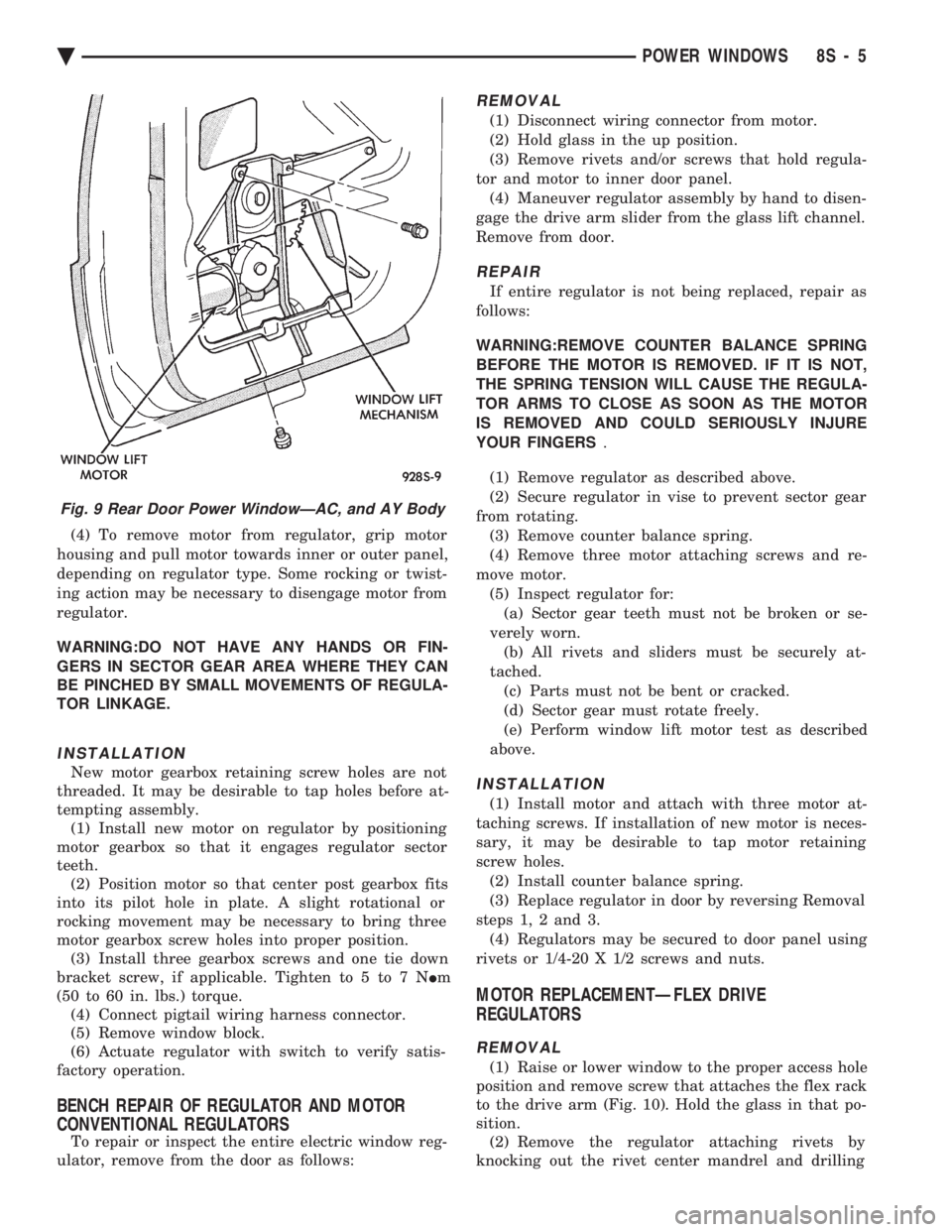
(4) To remove motor from regulator, grip motor
housing and pull motor towards inner or outer panel,
depending on regulator type. Some rocking or twist-
ing action may be necessary to disengage motor from
regulator.
WARNING:DO NOT HAVE ANY HANDS OR FIN-
GERS IN SECTOR GEAR AREA WHERE THEY CAN
BE PINCHED BY SMALL MOVEMENTS OF REGULA-
TOR LINKAGE.
INSTALLATION
New motor gearbox retaining screw holes are not
threaded. It may be desirable to tap holes before at-
tempting assembly. (1) Install new motor on regulator by positioning
motor gearbox so that it engages regulator sector
teeth. (2) Position motor so that center post gearbox fits
into its pilot hole in plate. A slight rotational or
rocking movement may be necessary to bring three
motor gearbox screw holes into proper position. (3) Install three gearbox screws and one tie down
bracket screw, if applicable. Tighten to 5 to 7 N Im
(50 to 60 in. lbs.) torque. (4) Connect pigtail wiring harness connector.
(5) Remove window block.
(6) Actuate regulator with switch to verify satis-
factory operation.
BENCH REPAIR OF REGULATOR AND MOTOR
CONVENTIONAL REGULATORS
To repair or inspect the entire electric window reg-
ulator, remove from the door as follows:
REMOVAL
(1) Disconnect wiring connector from motor.
(2) Hold glass in the up position.
(3) Remove rivets and/or screws that hold regula-
tor and motor to inner door panel. (4) Maneuver regulator assembly by hand to disen-
gage the drive arm slider from the glass lift channel.
Remove from door.
REPAIR
If entire regulator is not being replaced, repair as
follows:
WARNING:REMOVE COUNTER BALANCE SPRING
BEFORE THE MOTOR IS REMOVED. IF IT IS NOT,
THE SPRING TENSION WILL CAUSE THE REGULA-
TOR ARMS TO CLOSE AS SOON AS THE MOTOR
IS REMOVED AND COULD SERIOUSLY INJURE
YOUR FINGERS .
(1) Remove regulator as described above.
(2) Secure regulator in vise to prevent sector gear
from rotating. (3) Remove counter balance spring.
(4) Remove three motor attaching screws and re-
move motor. (5) Inspect regulator for:(a) Sector gear teeth must not be broken or se-
verely worn. (b) All rivets and sliders must be securely at-
tached. (c) Parts must not be bent or cracked.
(d) Sector gear must rotate freely.
(e) Perform window lift motor test as described
above.
INSTALLATION
(1) Install motor and attach with three motor at-
taching screws. If installation of new motor is neces-
sary, it may be desirable to tap motor retaining
screw holes. (2) Install counter balance spring.
(3) Replace regulator in door by reversing Removal
steps 1, 2 and 3. (4) Regulators may be secured to door panel using
rivets or 1/4-20 X 1/2 screws and nuts.
MOTOR REPLACEMENTÐFLEX DRIVE
REGULATORS
REMOVAL
(1) Raise or lower window to the proper access hole
position and remove screw that attaches the flex rack
to the drive arm (Fig. 10). Hold the glass in that po-
sition. (2) Remove the regulator attaching rivets by
knocking out the rivet center mandrel and drilling
Fig. 9 Rear Door Power WindowÐAC, and AY Body
Ä POWER WINDOWS 8S - 5
Page 737 of 2438
POWER MIRRORS
CONTENTS
page page
AUTOMATIC DAY/NIGHT INSIDE MIRROR .... 7
AUTOMATIC DAY/NIGHT INSIDE MIRROR WITH ULTRALIGHT HEADLAMP CONTROL ....... 7
GENERAL INFORMATION .................. 1
HEATED MIRROR ........................ 2
INSIDE MIRROR/READING LAMPS BULB/LENS REPLACEMENT ........................ 6
INSIDE MIRROR/READING LAMPS REPLACEMENT ........................ 6
MIRROR ASSEMBLY REPLACEMENTÐAA BODY.5
MIRROR ASSEMBLY REPLACEMENTÐ AC AND AY BODIES .................... 5
MIRROR ASSEMBLY REPLACEMENTÐAG BODY.5
MIRROR ASSEMBLY REPLACEMENTÐAJ BODY.5
MIRROR ASSEMBLY REPLACEMENTÐAP BODY.5
MIRROR MOTOR TEST PROCEDURE ........ 2
MIRROR SWITCH REPLACEMENTÐAA BODY . 3
MIRROR SWITCH REPLACEMENTÐAC AND AY BODIES .............................. 4
MIRROR SWITCH REPLACEMENTÐAG AND AJ BODIES .............................. 3
MIRROR SWITCH REPLACEMENTÐAP BODY . 4
MIRROR SWITCH TEST PROCEDURE ....... 2
TEST PROCEDURES ...................... 2
GENERAL INFORMATION
Electrically operated power mirrors are available
on all car lines. The mirrors are controlled by a sin-
gle switch assembly located either on the driver's
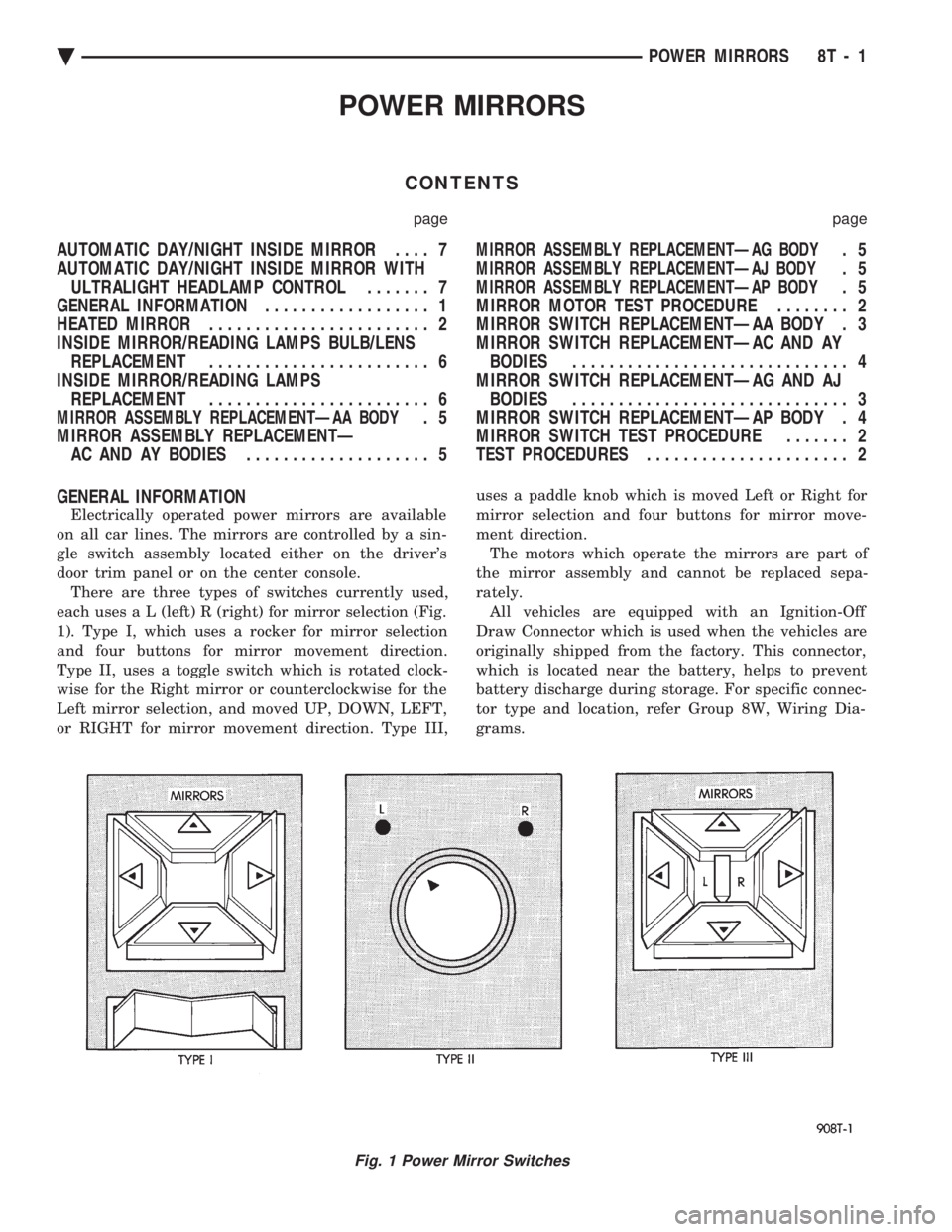
door trim panel or on the center console. There are three types of switches currently used,
each use s a L (left) R (right) for mirror selection (Fig.
1). Type I, which uses a rocker for mirror selection
and four buttons for mirror movement direction.
Type II, uses a toggle switch which is rotated clock-
wise for the Right mirror or counterclockwise for the
Left mirror selection, and moved UP, DOWN, LEFT,
or RIGHT for mirror movement direction. Type III, uses a paddle knob which is moved Left or Right for
mirror selection and four buttons for mirror move-
ment direction.
The motors which operate the mirrors are part of
the mirror assembly and cannot be replaced sepa-
rately. All vehicles are equipped with an Ignition-Off
Draw Connector which is used when the vehicles are
originally shipped from the factory. This connector,
which is located near the battery, helps to prevent
battery discharge during storage. For specific connec-
tor type and location, refer Group 8W, Wiring Dia-
grams.
Fig. 1 Power Mirror Switches
Ä POWER MIRRORS 8T - 1
Page 743 of 2438
AUTOMATIC DAY/NIGHT INSIDE MIRROR
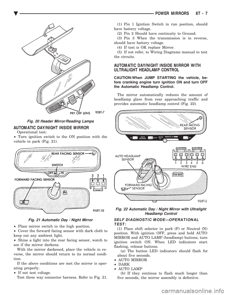
Operational test:
² Turn ignition switch to the ON position with the
vehicle in park (Fig. 21).
² Place mirror switch in the high position.
² Cover the forward facing sensor with dark cloth to
keep out any ambient light.
² Shine a light into the rear facing sensor, watch to
see if the mirror darkens. With the mirror darkened, place the vehicle in re-
verse, the mirror should return to its normal condi-
tion. If the above conditions are met the mirror is oper-
ating properly.
² If not test voltage.
Test three way connector harness. Refer to Fig. 21. (1) Pin 1 Ignition Switch in run position, should
have battery voltage. (2) Pin 2 Should have continuity to Ground.
(3) Pin 3 When the transmission is in reverse,
should have battery voltage. (4) If test is OK replace Mirror.
(5) If not refer, to Wiring Diagrams manual to test
the circuits.
AUTOMATIC DAY/NIGHT INSIDE MIRROR WITH
ULTRALIGHT HEADLAMP CONTROL
CAUTION:When JUMP STARTING the vehicle, be-
fore cranking engine turn ignition ON and turn OFF
the Automatic Headlamp Control.
The mirror automatically reduces the amount of
headlamp glare from rear approaching traffic and
provides automatic headlamp control (Fig. 22).
SELF DIAGNOSTIC MODEÐOPERATIONAL TEST:
(1) Place shift selector in park (P) or Neutral (N)
position. With ignition OFF, press and hold AUTO
MIRROR and AUTO LAMP (headlamp) buttons, turn
ignition switch ON. When LED indicators start
flashing, release buttons. (a) The button LED indicators should flash for
about five seconds.
² AUTO MIRROR
² DARK
² AUTO LAMP
(b) If they continue to flash much longer than
five seconds, the mirror assembly is defective.
Fig. 20 Header Mirror/Reading Lamps
Fig. 21 Automatic Day / Night Mirror
Fig. 22 Automatic Day / Night Mirror with Ultralight Headlamp Control
Ä POWER MIRRORS 8T - 7
Page 745 of 2438
CHIME WARNING/REMINDER SYSTEM
CONTENTS
page page
BODY CONTROLLER REPLACEMENT ........ 5
CHIME MODULE REPLACEMENT AA and AP BODIES .............................. 5
CHIME SYSTEM DIAGNOSISÐAA AND AP BODIES .............................. 2
CHIME SYSTEM DIAGNOSISÐAC, AG, AJ AND AY BODIES ....................... 3
CHIME WARNING/REMINDER SYSTEM TEST . 1 GENERAL INFORMATION
.................. 1
HEADLAMP SWITCH REPLACEMENT ........ 5
KEY-IN SWITCH REPLACEMENT ............ 5
SEAT BELT BUCKLE REPLACEMENT ........ 5
SEAT BELT BUCKLE SWITCH TEST BUZZER SYSTEM .............................. 1
SERVICE PROCEDURES ................... 5
TIMED BUZZER-RELAY TESTÐAP BODY ..... 1
GENERAL INFORMATION
WARNING: ON VEHICLES EQUIPPED WITH AN AIR
BAG REFER TO THE AIR BAG PORTION OF THIS
SECTION FOR STEERING WHEEL OR SWITCH RE-
MOVAL AND INSTALLATION PROCEDURES.
BUZZER SYSTEM
The seat belt warning system uses both visual and
audible signals. A combined seat belt and key warn-
ing buzzer with a red light on the instrument panel. The system will always illuminate the seat belt
warning lamp for four to eight seconds when the ig-
nition switch is turned to the ON position. Also, only
if the driver does not fasten his seat belt, the buzzer
will sound during the same time interval. Passenger
belts are not connected to the system. A timed buzzer-relay is used to operate the system
for the time period. It consists of a time delay mech-
anism and buzzer assembly. Only the driver's seat
belt buckle has a switch that is connected to the sys-
tem.
CHIME WARNING/REMINDER SYSTEM
The chime warning/reminder system is similar in
operation to the buzzer system except for a more
pleasant sounding tone. This chime type tone sounds
for all three warning/reminder conditions; namely
headlamps left on, keys left in ignition and fasten
seat belt.
TIMED BUZZER-RELAY TESTÐAP BODY
PREPARATION
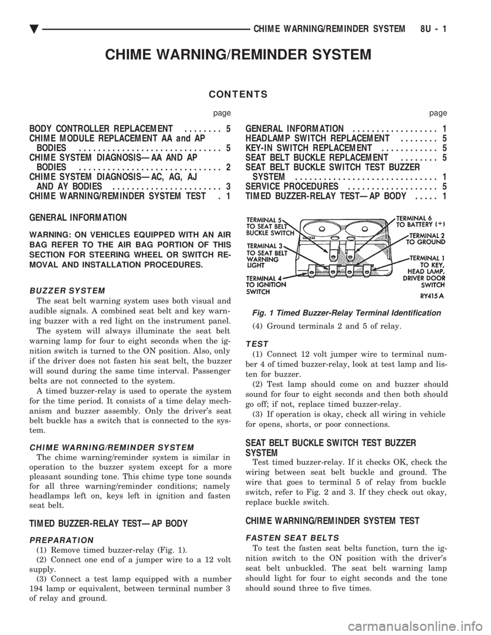
(1) Remove timed buzzer-relay (Fig. 1).
(2) Connect one end of a jumper wire to a 12 volt
supply. (3) Connect a test lamp equipped with a number
194 lamp or equivalent, between terminal number 3
of relay and ground. (4) Ground terminals 2 and 5 of relay.
TEST
(1) Connect 12 volt jumper wire to terminal num-
ber 4 of timed buzzer-relay, look at test lamp and lis-
ten for buzzer. (2) Test lamp should come on and buzzer should
sound for four to eight seconds and then both should
go off; if not, replace timed buzzer-relay. (3) If operation is okay, check all wiring in vehicle
for opens, shorts, or poor connections.
SEAT BELT BUCKLE SWITCH TEST BUZZER
SYSTEM
Test timed buzzer-relay. If it checks OK, check the
wiring between seat belt buckle and ground. The
wire that goes to terminal 5 of relay from buckle
switch, refer to Fig. 2 and 3. If they check out okay,
replace buckle switch.
CHIME WARNING/REMINDER SYSTEM TEST
FASTEN SEAT BELTS
To test the fasten seat belts function, turn the ig-
nition switch to the ON position with the driver's
seat belt unbuckled. The seat belt warning lamp
should light for four to eight seconds and the tone
should sound three to five times.
Fig. 1 Timed Buzzer-Relay Terminal Identification
Ä CHIME WARNING/REMINDER SYSTEM 8U - 1
Page 749 of 2438

CONDITION: NO TONE WHEN HEADLAMPS ARE ON AND DRIVER'S DOOR IS OPEN, ANDIGNITION IS OFF
PROCEDURE
(1) Check left door jamb switch for good ground
when driver's door is open. This may be checked at
terminal 1 of 25-way body controller connector. (2) Check for battery feed at terminal 16 of 25-way
body controller connector. (3) Check headlamp switch.
CONDITION: NO TONE WHEN KEY IS LEFT INIGNITION AND DRIVER'S DOOR IS OPEN
PROCEDURE
(1) Check left door jamb switch for good ground
when driver's door is open. This may be checked at
terminal 1 of 25-way body controller connector. (2) Check for battery feed at terminal 16 of 25-way
body controller connector. (3) Check key-in switch.
CONDITION: CHIMES CONTINUE WHENHEADLAMPS ARE TURNED OFF AND/OR KEYIS REMOVED FROM IGNITION
PROCEDURE
Check wiring for a grounded condition between
headlamp switch, key-in switch, and body controller.
SERVICE PROCEDURES
CHIME MODULE REPLACEMENT AA and AP
BODIES
(1) Open glove box door and disconnect check strap.
(2) Disconnect glove box light switch.
(3) Remove screws from glove box assembly and
remove. (4) Remove two screws from chime module mount-
ing bracket (Figs. 9 and 10). (5) Disconnect chime module wiring and remove
module. (6) For installation reverse above procedures.
BODY CONTROLLER REPLACEMENT
Refer to Group 8E, Instrument Panel and Gauges.
SEAT BELT BUCKLE REPLACEMENT
Refer to Group 23, Body of this service manual.
HEADLAMP SWITCH REPLACEMENT
Refer to Group 8E, Instrument Panel and Gauges.
KEY-IN SWITCH REPLACEMENT
The Key-in switch is built into the ignition switch as-
sembly. Should the Key-in switch require service, the
ignition switch assembly must be replaced. Refer to
Group 8D Ignition System of this service manual (Fig.
11).
Fig. 9 Chime Module LocationÐAA Body
Fig. 10 Chime Module Location
Fig. 11 Halo Lamp and Key-In Warning Switch Continuity
Ä CHIME WARNING/REMINDER SYSTEM 8U - 5