1993 CHEVROLET PLYMOUTH ACCLAIM instrument panel
[x] Cancel search: instrument panelPage 614 of 2438
TESTING PROCEDURES
MULTI-FUNCTION SWITCH TESTS AA, AC, AP, AND AY BODIES
The multi-function switch contains electrical cir-
cuitry for turn signal, cornering lamps (optional),
hazard warning, headlamp beam select, headlamp
optical horn, windshield wiper, pulse wipe, and wind-
shield washer switching. This integrated switch as-
sembly is mounted to the left hand side of the
steering column. Should any function of the switch
fail, the entire switch assembly must be replaced. Re-
fer to Fig. 1 for diagnosis. To test the switch, first disconnect the negative
battery cable, then remove the upper and lower col-
umn covers to gain access to the switch connector.
Remove switch connector. Using an ohmmeter, test
for continuity (no resistance) between the terminals
of the switch as shown in the following continuity
charts (Fig 2 or 3).
DUAL-FUNCTION SWITCH TESTSÐAG AND AJ BODIES
The dual-function switch contains electrical cir-
cuitry for hazard warning switching, and circuitry
and electronics for turn signal cancellation. The
switch assembly is mounted to the left hand side of
the steering column. To test the hazard warning portion of the switch,
first disconnect the negative battery cable, then re-
move the upper and lower steering column covers to
gain access to the switch connector. Remove switch
connector (Fig. 4). Using an ohmmeter, test for con-
tinuity between the terminals of the switch as shown
in the following continuity chart (Fig. 5). To test the cancellation portion of the switch:
(1) Reconnect battery and switch connector (Fig.
5). (2) Connect voltmeter positive lead (+) to pin 8
and negative lead (-) to ground. (3) Place ignition switch to the ON position. Volt-
meter should read battery voltage. If no voltage is
present, check feed wire to pin 8. If battery voltage is
present continue with switch test.
RIGHT CANCELLATION TEST (1) Connect one side of a jumper wire to pin 3 and
the other end of jumper wire to ground. (2) Connect the positive lead (+) of a voltmeter to
pin 5 and the negative lead (-) to ground.
CAUTION: Do not allow pin 5 to become grounded
during test, switch failure will result.
(3) With the ignition switch in the ON position,
push the cancellation pawl down and read the volt-
meter. (4) The voltmeter should show at least 9 volts. (5) If voltage is 0 to 8 volts the cancellation switch
is defective. If voltage is 9 volts or more the cancel-
lation switch is working correctly.
LEFT CANCELLATION TEST
(1) Connect one side of a jumper wire to pin 4 and
the other end of jumper wire to ground. (2) Connect the positive lead (+) of a voltmeter to
pin 5 and the negative lead (-) to ground.
CAUTION: Do not allow pin 5 to become grounded
during test, switch failure will result.
(3) With the ignition switch in the ON position,
push the cancellation pawl up and read the voltme-
ter. (4) The voltmeter should show at least 9 volts.
(5) If voltage is 0 to 8 volts the cancellation switch
is defective. If voltage is 9 volts or more the cancel-
lation switch is working correctly.
REMOTE TURN SIGNAL SWITCH TESTÐAA AND AJ BODIES
The remote turn signal switch is located on the left
side of the instrument panel switch pod. To test, re-
move switch pod assembly from instrument panel.
Using an ohmmeter, test for continuity between the
terminals of the switch as shown in the following
continuity chart (Fig. 6). The white 7 way connector
next to the 14 way connector must be connected
when performing continuity checks.
CANCELLATION SOLENOID TESTÐAG AND AJ BODIES
To test the turn signal cancellation solenoid:
(1) Remove switch pod from instrument panel.
(2) Connect one end of a jumper wire to the posi-
tive terminal of the battery, the other end to pin 6 of
the turn signal switch 14 way connector. (3) Place turn signal switch in the left turn mode.
(4) Take a second jumper wire and connect one end
to a good ground. Momentarily touch the other end of
the jumper wire to pin 11 or 14. The solenoid should
energize, and return the switch to its center OFF po-
sition. (5) Place turn signal switch in the right turn
mode. (6) Repeat step 4. The solenoid should energize,
and return the switch to its center OFF position. (7) If switch does not return to center in either di-
rection, the switch is defective.
MULTI-FUNCTION SWITCHÐAA, AC, AP AND AY
BODIES
REMOVAL
(1) Disconnect negative battery cable.
(2) Tilt column only remove tilt lever.
8J - 2 TURN SIGNALS AND HAZARD WARNING FLASHER Ä
Page 618 of 2438

(5) For installation reverse above procedure.
(6) Check for proper operation of all components
which are controlled by the pod mounted switch.
TURN SIGNAL AND HAZARD WARNING FLASHER
LOCATION
AA, AC, AP AND AY BODIES
The turn signal flasher and the hazard warning
flasher are two separate plug-in type units. On AC and AY both flashers are on the relay mod-
ule (Fig. 10).
On AA and AP Bodies the hazard flasher is located
on the relay module (Fig. 11). The turn signal flasher
is on the driver's side of A/C duct for AA Body (Fig.
12) and center A/C duct for AP Body.
AG AND AJ BODIES
The turn signal flasher and the hazard warning
flasher are combined into one unit called a combina-
tion flasher (combo-flasher). The combo-flasher con-
trols the flashing of the hazard warning system and the turn signal system. An inoperative bulb or in-
complete turn signal circuit will result in an increase
in flasher speed. The combo-flasher is located under the instrument
panel, right of the steering column and is clipped on
the A/C distribution duct. The combo-flasher is yel-
low in color for ease of identification.TURN SIGNAL RELAYSÐAG AND AJ BODIES
The AG and AJ models are equipped with four
turn signal relays.
Fig. 9 Remote Turn Signal SwitchÐAG and AJ Bodies
Fig. 10 Turn Signal and Hazard WarningFlasherÐAC and AY Bodies
Fig. 11 Hazard Warning FlasherÐAA and AP Bodies
Fig. 12 Turn Signal FlasherÐAA Body
8J - 6 TURN SIGNALS AND HAZARD WARNING FLASHER Ä
Page 619 of 2438
One relay controls the right rear turn signal and
stop lamp. The second relay controls the left rear
turn signal and stop lamp. The third relay controls
the right front turn signal. The fourth relay controls
the left front turn signal. The turn signal relays are located in the relay
bank, underneath the driver's side of the instrument
panel. The four turn signal relays are identical and
can be interchanged. The turn signal relays do not cycle on and off with
the turn signal lamp. Their function is to complete the turn signal circuit when the turn signal is
switched on. Turn signal cycling is done by the com-
bination flasher. To test the relay, remove the suspect relay and
switch it with 1 of the other 3 turn signal relays. If
the problem follows the relay, replace that relay. If
the problem remains in the same circuit, the relay is
not the problem. Refer to Group 8W, Wiring Dia-
grams.
Ä TURN SIGNALS AND HAZARD WARNING FLASHER 8J - 7
Page 635 of 2438
WIPER SWITCH SERVICE PROCEDURE
WARNING: ON VEHICLES EQUIPPED WITH AIR-
BAG, SEE GROUP 8M, RESTRAINT SYSTEMS FOR
STEERING WHEEL OR COLUMN REMOVAL PROCE-
DURES.
AC AND AY BODIES
The wiper switch is part of the multi-function
switch assembly. If the wiper switch fails, the multi-
function switch must be replaced. Refer to Group 8J,
Turn Signals and Hazard Warning Flasher for multi-
function switch service procedure.
AG AND AJ BODIES
REMOVAL
(1) Remove switch pod assembly from instrument
panel. (2) Remove five inner switch pod panel.
(3) Unhook switch linkage from buttons.
(4) Remove switch mounting screws.
(5) Remove switch.
INSTALLATION (1) Latch switch linkage in the up position.
(2) Insert switch into switch pod and install
mounting screws. (3) Unlatch linkage and install onto push buttons.
(4) Operate all switch modes for correct operation.
(5) Reinstall five inner switch pod panel screws.
(6) Reinstall switch pod assembly.
PULSE INTERMITTENT WINDSHIELD WIPER
CONTROLLER (PIWWC)
The controller is a part of the washing and wiper
system which includes:
² Pulse intermittent windshield wiper controller
² Wiper blades and arms
² Wiper motor
² Windshield washer reservoir
² Wiring harness
² Windshield washer pump
² Windshield washer hoses
Any part not working properly could cause, the
whole system not to work properly or at all. If the
system is not working proper, check all parts before
taking any action of part replacements.
The controller controls the pulse/wipe and the inter-
mittent modes only. The time delay in the intermittent
wipe mode is a minimum of 45 to a maximum of 25 sec-
onds depending on the switch setting.
The wash function can be turn ON with the wiper
control switch in the OFF position. Pressing the
wash button on the end of the level will operate the
washer pump until released. The wipers will operate
while the pump is operating and continue for about
three addition wipes ( 61) after before parking.
AA BODY
The PIWWC (Fig. 26) is attached to a bracket lo-
cated to the right of the steering column behind the
steering column cover (Fig. 27).
AP BODY
The PIWWC is attached to a bracket located to the
right of the steering column behind the steering col-
umn cover (Fig. 28).
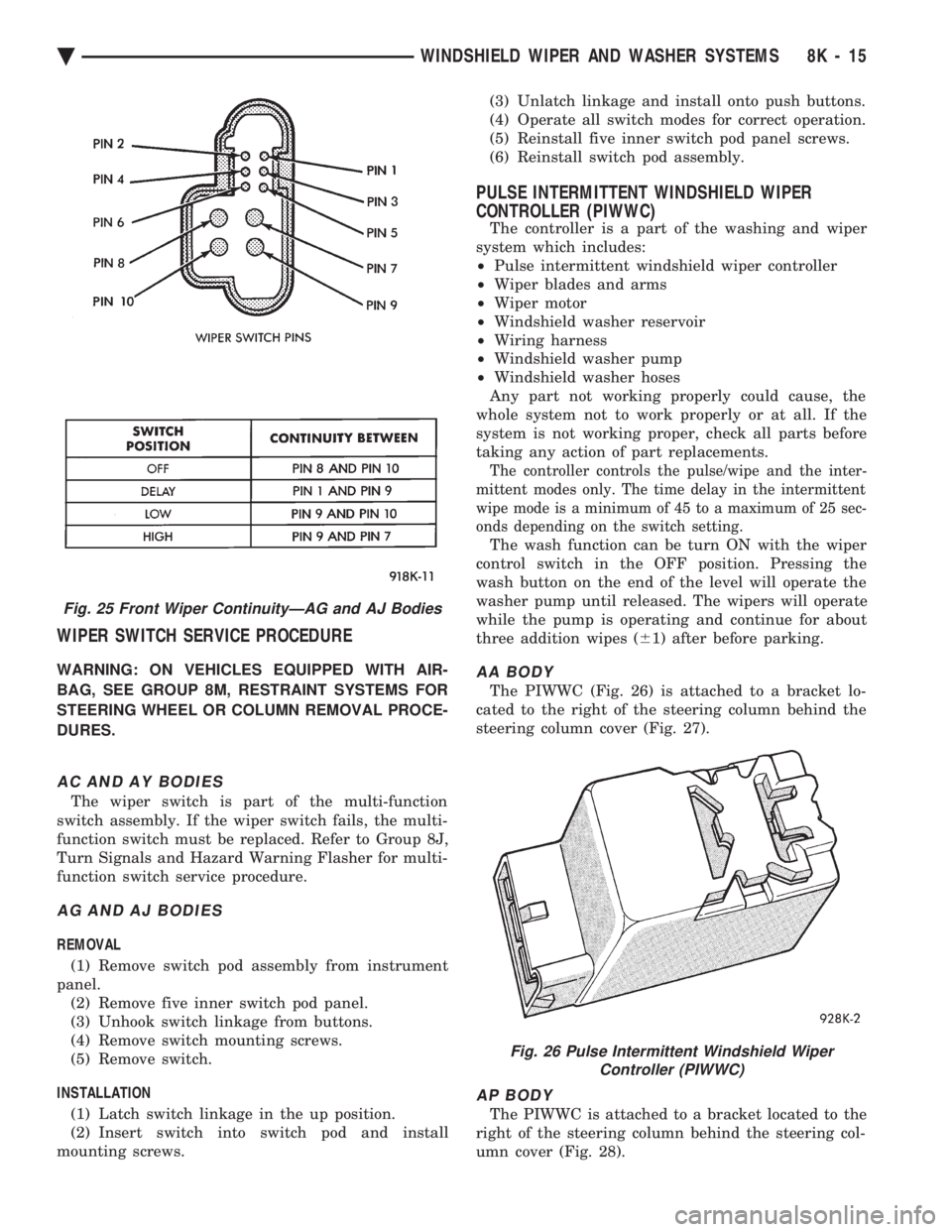
Fig. 25 Front Wiper ContinuityÐAG and AJ Bodies
Fig. 26 Pulse Intermittent Windshield Wiper Controller (PIWWC)
Ä WINDSHIELD WIPER AND WASHER SYSTEMS 8K - 15
Page 645 of 2438
EXTERIOR LAMP SWITCHES AND HEADLAMP ALIGNMENT INDEX
page page
Headlamp Adjustment Using Alignment Screen .... 3
Headlamp Alignment ....................... 3
Headlamp Alignment Preparation .............. 3 Headlamp Dimmer Switch
................... 3
Headlamp Switch .......................... 3
HEADLAMP SWITCH
Service procedures for the headlamp switch can be
found in Group 8E, Instrument Panel and Gauges. More
information can be found in Wiring Diagrams manual.
HEADLAMP DIMMER SWITCH
The headlamp dimmer switch is incorporated into
the turn signal switch. Proper procedures can be found
in Group 8J, Turn Signal and Flashers. More informa-
tion can be found in Group 8W, Wiring Diagrams.
HEADLAMP ALIGNMENT
Headlamps can be aligned using the screen method
provided in this section. Alignment Tool C4466-A or
equivalent can also be used. Refer to instructions
provided with the tool for proper procedures. The
preferred headlamp alignment setting is 0 for the
left/right adjustment and 0 for the up/down ad-
justment.
HEADLAMP ALIGNMENT PREPARATION
(1) Verify headlamp dimmer switch and high beam
indicator operation. (2) Inspect and correct damaged or defective compo-
nents that could interfere with proper headlamp align-
ment. (3) Verify proper tire inflation.
(4) Clean headlamp lenses.
(5) Verify that luggage area is not heavily loaded.
(6) Fuel tank should be FULL. Add 2.94 kg (6.5 lbs.)
of weight over the fuel tank for each estimated gallon of
missing fuel.
HEADLAMP ADJUSTMENT USING ALIGNMENT
SCREEN
ALIGNMENT SCREEN PREPARATION (FIG. 1 AND 2)
(1) Position vehicle on a level surface perpendicular
to a flat wall 7.62 meters (25 ft) away from front of
headlamp lens. (2) If necessary, tape a line on the floor 7.62 meters
(25 ft) away from and parallel to the wall.
(3) From the floor up 1.27 meters (5 ft), tape a line on
the wall at the centerline of the vehicle. Sight along the
centerline of the vehicle (from rear of vehicle forward) to
verify accuracy of the line placement.
(4) Rock vehicle side-to-side three times to allow
suspension to stabilize. (5) Jounce front suspension three times by pushing
downward on front bumper and releasing. (6) Measure the distance from the center of head-
lamp lens to the floor. Transfer measurement to the
alignment screen (with tape). Use this line for up/down
adjustment reference. (7) Measure distance from the centerline of the ve-
hicle to the center of each headlamp being aligned.
Transfer measurements to screen (with tape) to each
side of vehicle centerline. Use these lines for left/right
adjustment reference.
HEADLAMP ADJUSTMENT (FIG. 3, 4, 5, 6 OR 7)
A properly aimed low beam headlamp will project the
top edge of low beam hot spot on the alignment screen
from 50 mm (2 in.) above to 50 mm (2 in.) below the
headlamp centerline. The side-to-side left edge of low
beam hot spot should be from 50 mm (2 in.) left to
50mm (2 in.) right of headlamp centerline (Fig. 1). The
preferred headlamp alignment is 0 for the
up/down adjustment and 0 for the left/right ad-
justment. The high beams on a vehicle with aero
headlamps cannot be aligned. The high beam pattern
should be correct when the low beams are aligned
properly. To adjust headlamp alignment, rotate alignment
screws to achieve the specified low beam hot spot
pattern.
CAUTION: Do not cover an illuminated headlamp for
more then 15 seconds. Lamp will overheat and burn
or melt cover.
To adjust headlamps, rotate alignment screws to
achieve the specified high intensity pattern (Fig. 1 or
2).
FOG LAMP ALIGNMENT (FIG. 8)
Prepare an alignment screen. Refer to Alignment
Screen Preparation paragraph in this section. A prop-
erly aligned fog lamp will project a pattern on the
alignment screen 100 mm (4 in.) below the fog lamp
centerline and straight ahead.
Ä LAMPS 8L - 3
Page 667 of 2438
EXTERIOR LAMP SYSTEMS INDEX
page page
Daytime Running LampÐCanada Only ........ 25
Headlamp Time Delay System .............. 26
Lamp Outage ModuleÐAA-Body ............. 25 Lamp Outage ModuleÐAll Except AA-Body
..... 25
Lamp Outage System ..................... 25
Removal (Fig. 4) ......................... 25
LAMP OUTAGE SYSTEM
Diagnostics and component relationships for AC,
AG, AJ or AY-Bodies can be found in the Body Di-
agnostic Procedures Manual, Electronic Vehicle In-
formation Center (EVIC) section. For circuit and component locations on AA-body,
refer to the Wiring Diagrams Manual.
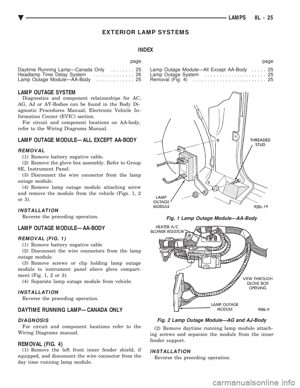
LAMP OUTAGE MODULEÐALL EXCEPT AA-BODY
REMOVAL
(1) Remove battery negative cable.
(2) Remove the glove box assembly. Refer to Group
8E, Instrument Panel. (3) Disconnect the wire connector from the lamp
outage module. (4) Remove lamp outage module attaching screw
and remove the module from the vehicle (Figs. 1, 2
or 3).
INSTALLATION
Reverse the preceding operation.
LAMP OUTAGE MODULEÐAA-BODY
REMOVAL (FIG. 1)
(1) Remove battery negative cable
(2) Disconnect the wire connectors from the lamp
outage module. (3) Remove screws or clip holding lamp outage
module to instrument panel above glove compart-
ment (Fig. 1, 2 or 3). (4) Separate lamp outage module from vehicle.
INSTALLATION
Reverse the preceding operation.
DAYTIME RUNNING LAMPÐCANADA ONLY
DIAGNOSIS
For circuit and component locations refer to the
Wiring Diagrams manual.
REMOVAL (FIG. 4)
(1) Remove the left front inner fender shield, if
equipped, and disconnect the wire connector from the
day time running lamp module. (2) Remove daytime running lamp module attach-
ing screws and separate the module from the inner
fender support.INSTALLATION
Reverse the preceding operation.
Fig. 1 Lamp Outage ModuleÐAA-Body
Fig. 2 Lamp Outage ModuleÐAG and AJ-Body
Ä LAMPS 8L - 25
Page 669 of 2438
CONCEALED HEADLAMPS INDEX
page page
Concealed Headlamp MotorÐAC-Body ........ 29
Diagnostic Procedures ..................... 27
General Information ....................... 27 Headlamp DoorÐAC-Body
................. 29
Headlamp DoorÐAY Body ................. 29
Headlamp Drive MotorÐAY Body ............ 30
GENERAL INFORMATION
For proper operation of the Concealed Headlamp
System, refer to the Owner's Manual provided with
the vehicle.
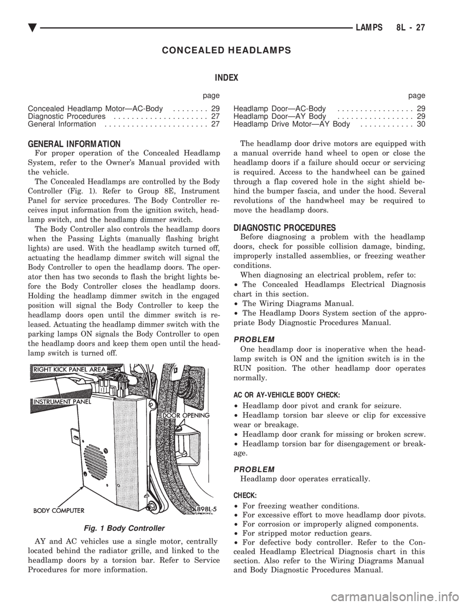
The Concealed Headlamps are controlled by the Body
Controller (Fig. 1). Refer to Group 8E, Instrument
Panel for service procedures. The Body Controller re-
ceives input information from the ignition switch, head-
lamp switch, and the headlamp dimmer switch. The Body Controller also controls the headlamp doors
when the Passing Lights (manually flashing bright
lights) are used. With the headlamp switch turned off,
actuating the headlamp dimmer switch will signal the
Body Controller to open the headlamp doors. The oper-
ator then has two seconds to flash the bright lights be-
fore the Body Controller closes the headlamp doors.
Holding the headlamp dimmer switch in the engaged
position will signal the Body Controller to keep the
headlamp doors open until the dimmer switch is re-
leased. Actuating the headlamp dimmer switch with the
parking lamps ON signals the Body Controller to open
the headlamp doors and keep them open until the head-
lamp switch is turned off.
AY and AC vehicles use a single motor, centrally
located behind the radiator grille, and linked to the
headlamp doors by a torsion bar. Refer to Service
Procedures for more information. The headlamp door drive motors are equipped with
a manual override hand wheel to open or close the
headlamp doors if a failure should occur or servicing
is required. Access to the handwheel can be gained
through a flap covered hole in the sight shield be-
hind the bumper fascia, and under the hood. Several
revolutions of the handwheel may be required to
move the headlamp doors.
DIAGNOSTIC PROCEDURES
Before diagnosing a problem with the headlamp
doors, check for possible collision damage, binding,
improperly installed assemblies, or freezing weather
conditions. When diagnosing an electrical problem, refer to:
² The Concealed Headlamps Electrical Diagnosis
chart in this section.
² The Wiring Diagrams Manual.
² The Headlamp Doors System section of the appro-
priate Body Diagnostic Procedures Manual.
PROBLEM
One headlamp door is inoperative when the head-
lamp switch is ON and the ignition switch is in the
RUN position. The other headlamp door operates
normally.
AC OR AY-VEHICLE BODY CHECK:
² Headlamp door pivot and crank for seizure.
² Headlamp torsion bar sleeve or clip for excessive
wear or breakage.
² Headlamp door crank for missing or broken screw.
² Headlamp torsion bar for disengagement or break-
age.
PROBLEM
Headlamp door operates erratically.
CHECK:
² For freezing weather conditions.
² For excessive effort to move headlamp door pivots.
² For corrosion or improperly aligned components.
² For stripped motor reduction gears.
² For defective body controller. Refer to the Con-
cealed Headlamp Electrical Diagnosis chart in this
section. Also refer to the Wiring Diagrams Manual
and Body Diagnostic Procedures Manual.
Fig. 1 Body Controller
Ä LAMPS 8L - 27
Page 676 of 2438
² The Illuminated Entry DiagnosisÐAC, AG, AJ
and AY-BODY chart in this section.
² The Illuminated Entry System section of the ap-
propriate Body Diagnostic Procedures Manual.
² The Wiring Diagrams Manual.
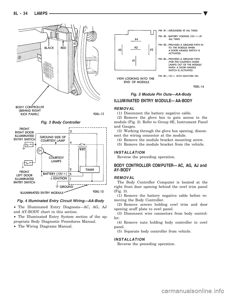
ILLUMINATED ENTRY MODULEÐAA-BODY
REMOVAL
(1) Disconnect the battery negative cable.
(2) Remove the glove box to gain access to the
module (Fig. 2). Refer to Group 8E, Instrument Panel
and Gauges. (3) Working through the glove box opening, discon-
nect the wiring connector at the module. (4) Remove the module bracket mounting screw.
(5) Remove the module bracket from the vehicle.
INSTALLATION
Reverse the preceding operation.
BODY CONTROLLER COMPUTERÐAC, AG, AJ and
AY-BODY
REMOVAL
The Body Controller Computer is located at the
right front door opening behind the cowl trim panel
(Fig. 3). (1) Remove the battery negative cable before re-
moving the Body Controller. (2) Remove screws holding cowl trim and door
opening scuff plate to cowl panel. (3) Disconnect wire connectors from body control-
ler. (4) Remove nuts holding body controller to cowl
panel. (5) Separate body controller from vehicle.
INSTALLATION
Reverse the preceding operation.
Fig. 3 Body Controller
Fig. 4 Illuminated Entry Circuit WiringÐAA-Body
Fig. 5 Module Pin OutsÐAA-Body
8L - 34 LAMPS Ä