1993 CHEVROLET PLYMOUTH ACCLAIM instrument panel
[x] Cancel search: instrument panelPage 567 of 2438

AUDIO SYSTEM
CONTENTS
page page
ANTENNAS ............................ 20
COMPACT DISC PLAYER ................. 30 RADIOS
................................ 1
SPEAKERS ............................ 24
RADIOS INDEX
page page
Audio Diagnostic Test Procedures ............. 1
Description .............................. 1
Interference Elimination ..................... 1
Radio Removal AP Body Replacement ........ 19 Radio RemovalÐAA Body
.................. 18
Radio RemovalÐAC and AY Bodies .......... 18
Radio RemovalÐAG and AJ Bodies .......... 18
DESCRIPTION
For operation of the factory installed standard and
optional radios and the optional compact disc player,
refer to the Sound Systems Operating Instructions
Manual supplied with the vehicle. All vehicles are equipped with an Ignition-Off
Draw Connector which, is used when the vehicles are
originally shipped from the factory. This connector
which, is located near the battery, helps to prevent
battery discharge during storage. For specific connec-
tor type and location, refer to Group 8W, Wiring Di-
agrams. This connector is included in the radio memory cir-
cuitry and should be checked if the memory of time
or radio station programming is inoperative.
INTERFERENCE ELIMINATION
Some components are used on vehicles equipped
with a radio capacitor, to suppress radio frequency
interference/static. Capacitors are mounted in various locations, on the
generator either internal or external, internal to the
instrument cluster, and internal to the windshield
wiper motor. Ground straps are mounted from radio chassis to
instrument panel support structure, engine to cowl,
across engine mount on right hand side. On vehicles
with air conditioning there is a strap from evapora-
tor valve to cowl. These ground straps should be se-
curely tightened to assure good metal to metal
contact. Ground straps conduct very small high fre-
quency electrical signals to ground and require clean
large surface area contact. Radio resistance type spark plug cables in the high
tension circuit of the ignition system complete the in-
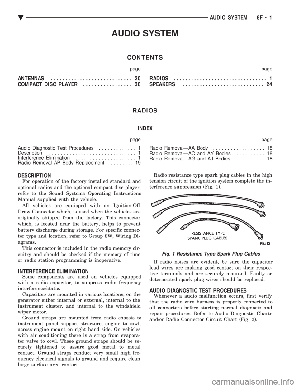
terference suppression (Fig. 1).
If radio noises are evident, be sure the capacitor
lead wires are making good contact on their respec-
tive terminals and are securely mounted. Faulty or
deteriorated spark plug wires should be replaced.
AUDIO DIAGNOSTIC TEST PROCEDURES
Whenever a audio malfunction occurs, first verify
that the radio wire harness is properly connected to
all connectors before starting normal diagnosis and
repair procedures. Refer to Audio Diagnostic Charts
and/or Radio Connector Circuit Chart (Fig. 2).
Fig. 1 Resistance Type Spark Plug Cables
Ä AUDIO SYSTEM 8F - 1
Page 584 of 2438

RADIO REMOVALÐAA BODY
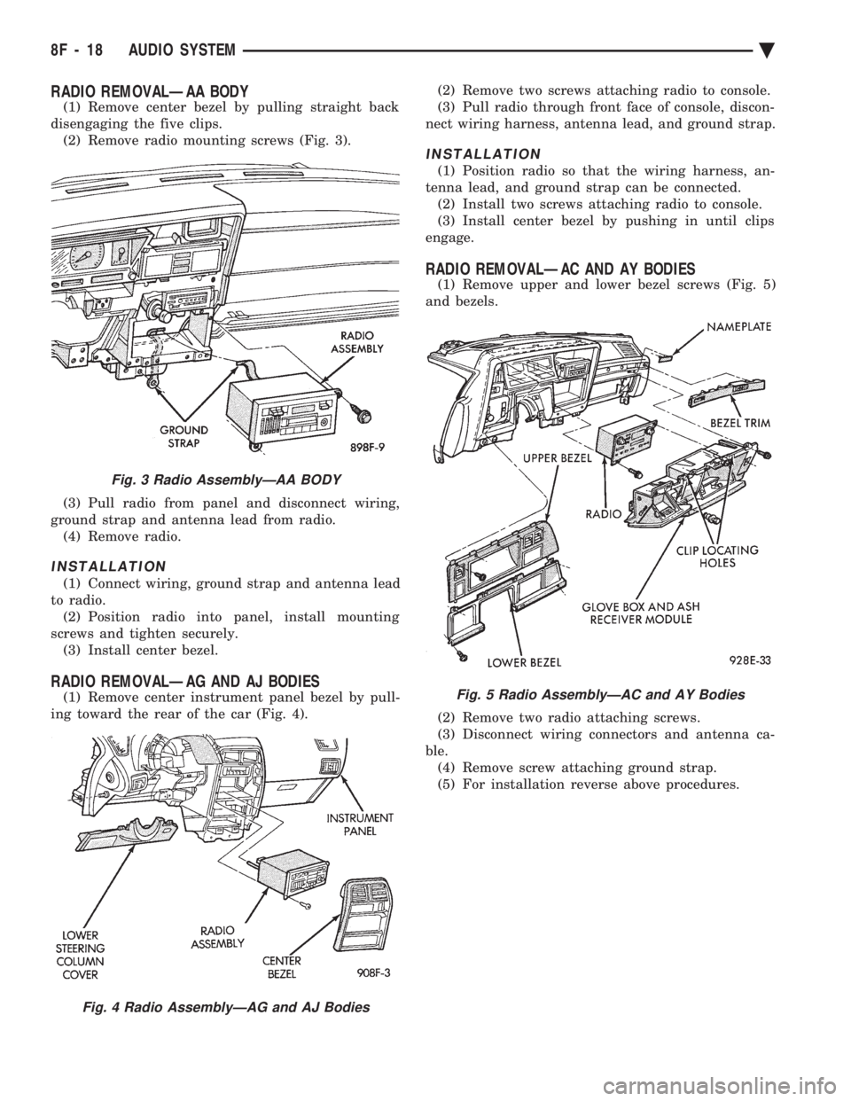
(1) Remove center bezel by pulling straight back
disengaging the five clips. (2) Remove radio mounting screws (Fig. 3).
(3) Pull radio from panel and disconnect wiring,
ground strap and antenna lead from radio. (4) Remove radio.
INSTALLATION
(1) Connect wiring, ground strap and antenna lead
to radio. (2) Position radio into panel, install mounting
screws and tighten securely. (3) Install center bezel.
RADIO REMOVALÐAG AND AJ BODIES
(1) Remove center instrument panel bezel by pull-
ing toward the rear of the car (Fig. 4). (2) Remove two screws attaching radio to console.
(3) Pull radio through front face of console, discon-
nect wiring harness, antenna lead, and ground strap.
INSTALLATION
(1) Position radio so that the wiring harness, an-
tenna lead, and ground strap can be connected. (2) Install two screws attaching radio to console.
(3) Install center bezel by pushing in until clips
engage.
RADIO REMOVALÐAC AND AY BODIES
(1) Remove upper and lower bezel screws (Fig. 5)
and bezels.
(2) Remove two radio attaching screws.
(3) Disconnect wiring connectors and antenna ca-
ble. (4) Remove screw attaching ground strap.
(5) For installation reverse above procedures.
Fig. 3 Radio AssemblyÐAA BODY
Fig. 4 Radio AssemblyÐAG and AJ Bodies
Fig. 5 Radio AssemblyÐAC and AY Bodies
8F - 18 AUDIO SYSTEM Ä
Page 585 of 2438

RADIO REMOVAL AP BODY REPLACEMENT
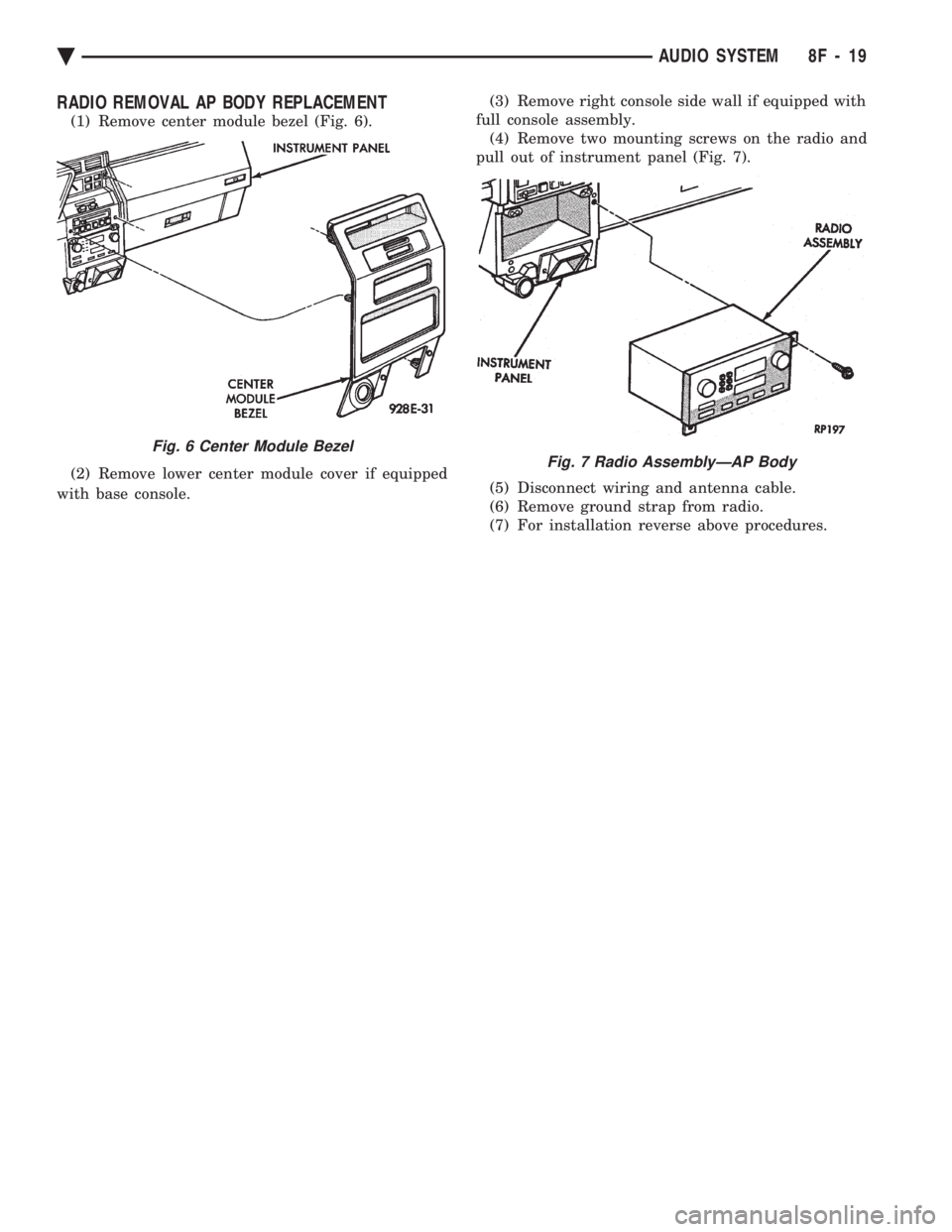
(1) Remove center module bezel (Fig. 6).
(2) Remove lower center module cover if equipped
with base console. (3) Remove right console side wall if equipped with
full console assembly. (4) Remove two mounting screws on the radio and
pull out of instrument panel (Fig. 7).
(5) Disconnect wiring and antenna cable.
(6) Remove ground strap from radio.
(7) For installation reverse above procedures.
Fig. 6 Center Module Bezel
Fig. 7 Radio AssemblyÐAP Body
Ä AUDIO SYSTEM 8F - 19
Page 590 of 2438

SPEAKERS INDEX
page page
AA Body ............................... 24
AC and AY Bodies ....................... 27
AC and AY Bodies ....................... 24
AG and AJ Bodies ....................... 25 AP Body
............................... 26
Infinity Remote Amplifier ................... 28
Relay/ChokeÐInfinity Speaker ............... 29
AA BODY
FRONT DOOR MOUNTED SPEAKER
REPLACEMENT
(1) Remove power window switch.
(2) Pry out on speaker grille at two locations on
forward edge of grille to disengage clips (Fig. 20).
(3) Remove two speaker mounting screws.
(4) Pull speaker away from door and disconnect
wiring connector. (5) For installation reverse the above procedures.
REAR DOOR MOUNTED SPEAKERREPLACEMENT
(1) Carefully pry with a blunt edge tool at the two
slotted openings on top edge of grille to disengage
clips. (2) Tilt top edge of grille away from door and lift
up to disengage plastic hooks on grille from trim
panel. (3) To aid in removing speaker it may be necessary
to disengage door trim panel near speaker opening. (4) Remove speaker-adaptor retaining screws (Fig.
21).
(5) Pull speaker away from door and disconnect
wiring connector. (6) For installation reverse above procedures.
AC and AY BODIES
INSTRUMENT PANEL SPEAKERSREPLACEMENT
(1) Carefully pry up at rearward corners of grille
with a blunt edge tool to disengage two plastic posts
from receptacle cavities in the instrument panel pad. (2) As rearward edge of grille comes free of pad in-
sert your fingers under exposed grille surface and
push up to disengage two more posts at forward cor-
ners of grille. (3) Remove two speaker attaching screws.
(4) Lift up speaker and disconnect wire connector.
Remove speaker. (5) For installation reverse above procedures.
FRONT DOOR SPEAKER REMOVAL
(1) Remove door trim panel, refer to Group 23,
Body.
Fig. 20 Front Door Mounted SpeakerÐAA Body
Fig. 21 Rear Door Mounted SpeakerÐAA Body
8F - 24 AUDIO SYSTEM Ä
Page 591 of 2438

(2) Remove two speaker attaching screws and dis-
connect wire connector. (3) Remove speaker.
(4) For installation reverse above procedures.
REAR SHELF SPEAKERS REMOVAL
(1) Remove rear shelf, refer to Group 23, Body.
(2) Remove two speaker attaching screws and dis-
connect wire connector. (3) Remove speaker.
(4) For installation reverse above procedures.
AG and AJ BODIES
INSTRUMENT PANEL SPEAKERS REPLACEMENT
(1) Remove instrument panel top cover (Fig. 22).
(2) Remove two speaker retaining screws.
(3) Lift speaker away from panel and disconnect
wiring. (4) For installation reverse above procedures.
FRONT DOOR MOUNTED SPEAKERREPLACEMENTÐAG BODY
(1) Remove door trim panel.
(2) Remove two speaker-adaptor retaining screws
(Fig. 23). (3) Pull speaker away from door and disconnect
wiring. (4) For installation reverse above procedures.
REAR SPEAKER REPLACEMENTÐAG BODY
(1) Remove speaker grille by pulling away from
quarter trim panel to disengage retaining clips (Fig.
24). (2) Remove four speaker retaining screws.
(3) Pull speaker away from body and disconnect
wiring. (4) For installation reverse above procedures.
DOOR MOUNTED SPEAKER
REPLACEMENTÐAJ BODY
(1) Pull speaker grille away from door trim panel
to disengage retaining clips (Fig. 25). (2) Remove two speaker retaining screws.
(3) Pull speaker away from door and disconnect
wiring. (4) For installation reverse above procedures.
REAR SPEAKER REPLACEMENTÐAJ BODYWITH 60/40 FOLDING REAR SEAT
(1) Remove 40-side seat back.
(2) Remove 60-side seat back.
(3) Remove outboard pivot brackets.
Fig. 22 Instrument Panel SpeakersÐAG and AJ Bodies
Fig. 23 Front Door Mounted SpeakerÐAG Body
Fig. 24 Rear SpeakerÐAG Body
Ä AUDIO SYSTEM 8F - 25
Page 593 of 2438

REAR MOUNTED SPEAKER REPLACEMENTÐAP BODY
(1) Remove cargo side trim panel (Fig. 29).
(2) Reaching up underneath quarter panel exten-
sion, remove four speaker retaining nuts (Fig. 30). (3) Move speaker away from mounting bracket and
disconnect wiring. (4) For installation reverse above procedures.
AC AND AY BODIES
INSTRUMENT PANEL SPEAKERREPLACEMENT
(1) Carefully, pry speaker grille away from instru-
ment panel (Fig. 31). (2) Remove two speaker retaining screws. (3) Lift speaker away from panel and disconnect
wiring. (4) For installation reverse above procedures.
DOOR MOUNTED SPEAKER REPLACEMENTÐAC AND AY BODIES
(1) Carefully, pry speaker grille away from door
trim panel (Fig. 32). (2) Remove two speaker retaining screws.
(3) Pull speaker away from door and disconnect
wiring. (4) For installation reverse above procedures.
REAR SPEAKER REPLACEMENTÐAC AND AYBODIES
(1) Remove seat cushion.
(2) Remove seat back.
Fig. 28 Door Mounted SpeakerÐAP Body
Fig. 29 Cargo Side Trim PanelÐAP Body
Fig. 30 Rear Mounted SpeakerÐAP Body
Fig. 31 Instrument Panel SpeakersÐAC and AY Bodies
Ä AUDIO SYSTEM 8F - 27
Page 596 of 2438

COMPACT DISC PLAYER
WARNING: USE OF THE CONTROLS, ADJUST-
MENTS, OR SERVICE PROCEDURES NOT SPECI-
FIED HERE OR IN THE OWNER MANUAL MAY
RESULT IN HAZARDOUS RADIATION EXPOSURE.
REPAIR PROCEDURES SHOULD ONLY BE PER-
FORMED BY A TRAINED TECHNICIAN.
DIAGNOSIS TEST
Power to the compact disc player is supplied by the
radio through the CD interface cable. The compact
disc player will only work with the radio system
turned ON. When a compact disc is inserted with the
label side facing up, the disc is automatically loaded
and will begin to play. The CD player may eject the disc with a display of
E under the following conditions:
² The surface of the disc is dirty or wet
² The disc was inserted with the label side facing
down
² The disc is defective
² The CD player may skip or mute while playing a
disc under severe vibration conditions example pot
holes, railroad tracks, etc.
² If the CD player becomes too hot at temperatures
above 60ÉC (140 ÉF) the CD player will shut down
with a display of HOT until it cools down. Refer to
the Audio Diagnostic Charts.
COMPACT DISC PLAYER REPLACEMENT
With intergral compact disc player refer to Radio
Removal.
AJ BODY
(1) Remove center instrument panel bezel by pull-
ing toward the rear of the car. (2) Remove two screws attaching disc player to
console (Fig. 36). (3) Pull disc player out of console and disconnect
interface cable. (4) To install compact disc player, above the re-
moval procedures.
Fig. 36 Compact Disc Player
8F - 30 AUDIO SYSTEM Ä
Page 613 of 2438

TURN SIGNALS AND HAZARD WARNING FLASHER
CONTENTS
page page
AG AND AJ BODIES ..................... 1
CHIME FUNCTIONÐAC, AG, AJ AND AY .... 1
DUAL-FUNCTION SWITCHÐAG AND AJ BODIES.5
GENERAL INFORMATION .................. 1
HAZARD WARNING SYSTEM .............. 1
MULTI-FUNCTION SWITCHÐAA, AC, AP AND AY BODIES .............................. 2 REMOTE TURN SIGNAL SWITCH REMOVALÐAG
AND AJ BODIES ....................... 5
TESTING PROCEDURES ................... 2
TURN SIGNAL AND HAZARD WARNING FLASHER LOCATION ............................ 6
TURN SIGNAL RELAYSÐAG AND AJ BODIES . 6
GENERAL INFORMATION
WARNING: ON VEHICLES EQUIPPED WITH AIR-
BAG, SEE GROUP 8M, RESTRAINT SYSTEMS FOR
AIRBAG REMOVAL PROCEDURES.
TURN SIGNALSÐAC, AY, AA AND AP BODIES
The turn signals are part of the multi-function switch.
Which contains electrical circuitry for turn signal, cor-
nering lamps, hazard warning, headlamp beam select,
headlamp optical horn, windshield wiper, pulse wipe
and windshield washer switching. The integrated switch
assembly is mounted to the left hand side of the steer-
ing column. When the driver wishes to signal his inten-
tions to change direction of travel, he moves the lever
upward to cause the right signals to flash and down-
ward to cause the left signals to flash. After completion
of a turn the system is deactivated automatically. As
the steering wheel returns to the straight ahead posi-
tion, a canceling cam of two lobes molded to the clock-
spring mechanism comes in contact with the cancel
actuator on the turn signal multi-function switch as-
sembly. Either cam lobe, pushing on the cancel actua-
tor, returns the switch to the off position. If only momentary signaling such as indication of a
lane change is desired, the switch is actuated to a left
or right intermediate detent position. In this position
the signal lamps flash as described above, but the
switch returns to the OFF position as soon as the lever
is released.
When the system is activated, 1 of 2 indicator
lamps mounted in the instrument cluster flashes in
unison with the turn signal lamps, indicating to the
driver that the system is operating.
AG AND AJ BODIES
The turn signals are actuated with lever on the left
side of the instrument panel switch pod. When the
driver wishes to signal his intentions to change di- rection of travel, he moves the lever upward to cause
the right signals to flash and downward to cause the
left signals to flash. After completion of a turn the system is deacti-
vated automatically. The cancellation switch in the
steering column sends a signal to a remote turn sig-
nal switch in the switch pod to cancel the turn signal
function. As the steering wheel returns to the
straight ahead position from a turn, a cancel cam
which is located on the steering wheel contacts a
cancel flipper located on the cancellation switch.
When the flipper is contacted by the cancel cam in
the proper rotational direction, the cancel switch
sends a signal to the remote turn signal switch. If only momentary signaling such as indication of a
lane change is desired, the switch is actuated to a
left or right intermediate detent position. In this po-
sition the signal lamps flash as described above, but
the switch returns to the OFF position as soon as the
lever is released. When the system is activated, 1 of 2 indicator
lamps mounted in the instrument cluster flashes in
unison with the turn signal lamps, indicating to the
driver that the system is operating.
HAZARD WARNING SYSTEM
The hazard warning system is actuated by a push
button located on the top of the steering column be-
tween the steering wheel and the instrument panel.
The hazard switch is identified with a double trian-
gle on top of the button. Push and release the button
to turn the hazard function ON or OFF. The button
will move out from the steering column in the ON
position and will remain in toward the column in the
OFF position.
CHIME FUNCTIONÐAC, AG, AJ AND AY
The chime will sound after the vehicle has traveled
a distance of 0.6 miles at a speed above 15 miles per
hour.
Ä TURN SIGNALS AND HAZARD WARNING FLASHER 8J - 1