1993 CHEVROLET PLYMOUTH ACCLAIM door lock
[x] Cancel search: door lockPage 2258 of 2438
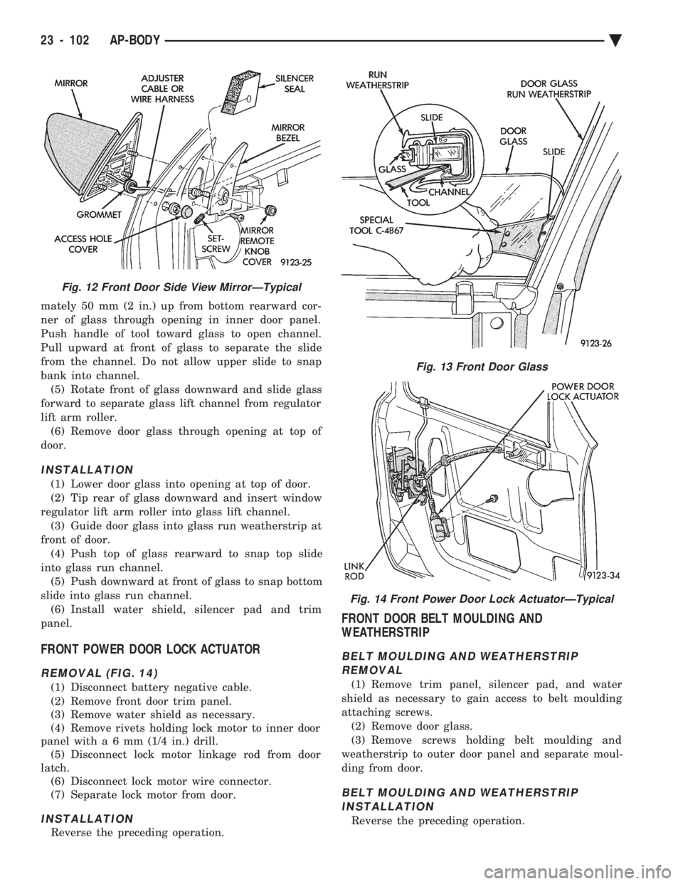
mately 50 mm (2 in.) up from bottom rearward cor-
ner of glass through opening in inner door panel.
Push handle of tool toward glass to open channel.
Pull upward at front of glass to separate the slide
from the channel. Do not allow upper slide to snap
bank into channel. (5) Rotate front of glass downward and slide glass
forward to separate glass lift channel from regulator
lift arm roller. (6) Remove door glass through opening at top of
door.
INSTALLATION
(1) Lower door glass into opening at top of door.
(2) Tip rear of glass downward and insert window
regulator lift arm roller into glass lift channel. (3) Guide door glass into glass run weatherstrip at
front of door. (4) Push top of glass rearward to snap top slide
into glass run channel. (5) Push downward at front of glass to snap bottom
slide into glass run channel. (6) Install water shield, silencer pad and trim
panel.
FRONT POWER DOOR LOCK ACTUATOR
REMOVAL (FIG. 14)
(1) Disconnect battery negative cable.
(2) Remove front door trim panel.
(3) Remove water shield as necessary.
(4) Remove rivets holding lock motor to inner door
panel wit ha6mm (1/4 in.) drill.
(5) Disconnect lock motor linkage rod from door
latch. (6) Disconnect lock motor wire connector.
(7) Separate lock motor from door.
INSTALLATION
Reverse the preceding operation.
FRONT DOOR BELT MOULDING AND
WEATHERSTRIP
BELT MOULDING AND WEATHERSTRIP
REMOVAL
(1) Remove trim panel, silencer pad, and water
shield as necessary to gain access to belt moulding
attaching screws. (2) Remove door glass.
(3) Remove screws holding belt moulding and
weatherstrip to outer door panel and separate moul-
ding from door.
BELT MOULDING AND WEATHERSTRIP INSTALLATION
Reverse the preceding operation.
Fig. 12 Front Door Side View MirrorÐTypical
Fig. 13 Front Door Glass
Fig. 14 Front Power Door Lock ActuatorÐTypical
23 - 102 AP-BODY Ä
Page 2262 of 2438
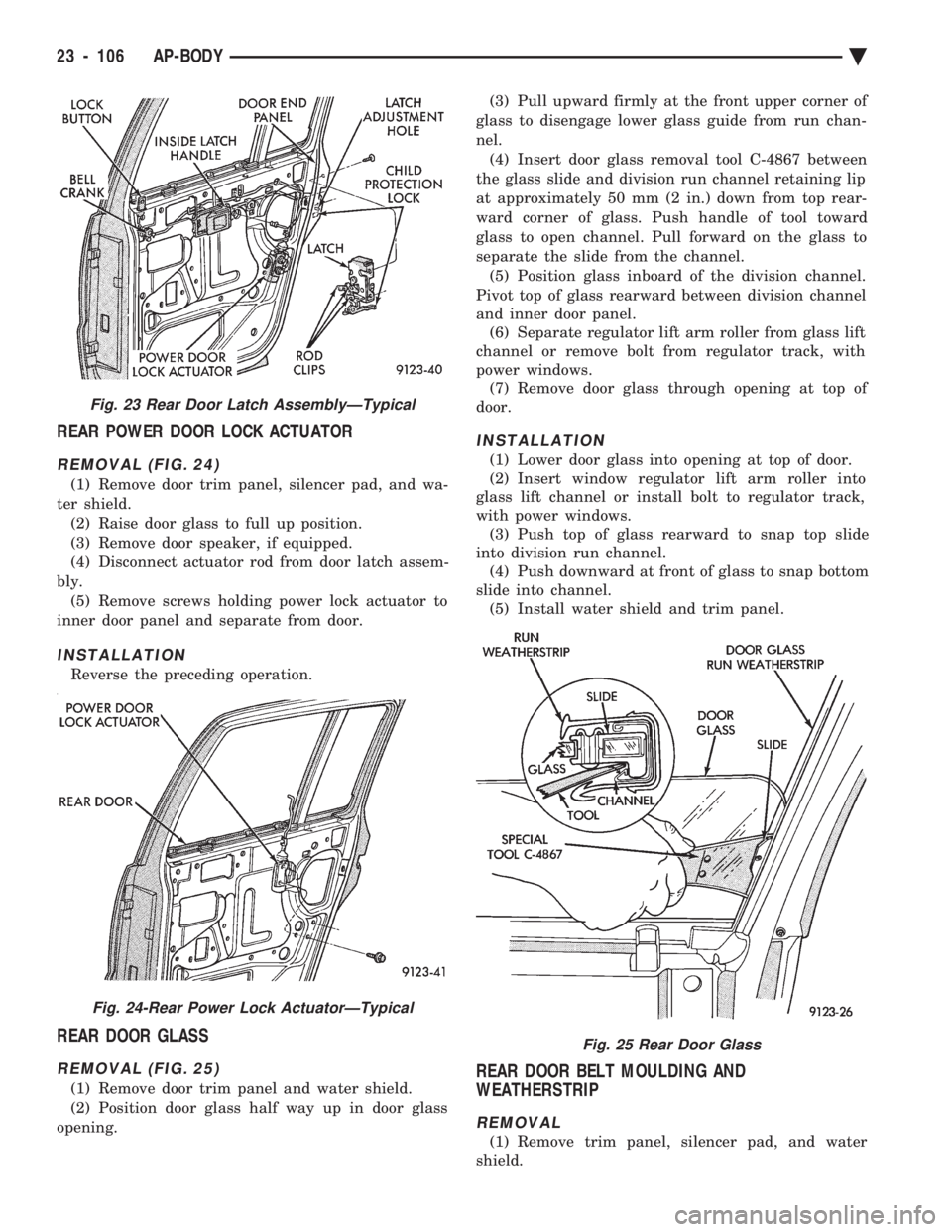
REAR POWER DOOR LOCK ACTUATOR
REMOVAL (FIG. 24)
(1) Remove door trim panel, silencer pad, and wa-
ter shield. (2) Raise door glass to full up position.
(3) Remove door speaker, if equipped.
(4) Disconnect actuator rod from door latch assem-
bly. (5) Remove screws holding power lock actuator to
inner door panel and separate from door.
INSTALLATION
Reverse the preceding operation.
REAR DOOR GLASS
REMOVAL (FIG. 25)
(1) Remove door trim panel and water shield.
(2) Position door glass half way up in door glass
opening. (3) Pull upward firmly at the front upper corner of
glass to disengage lower glass guide from run chan-
nel. (4) Insert door glass removal tool C-4867 between
the glass slide and division run channel retaining lip
at approximately 50 mm (2 in.) down from top rear-
ward corner of glass. Push handle of tool toward
glass to open channel. Pull forward on the glass to
separate the slide from the channel. (5) Position glass inboard of the division channel.
Pivot top of glass rearward between division channel
and inner door panel. (6) Separate regulator lift arm roller from glass lift
channel or remove bolt from regulator track, with
power windows. (7) Remove door glass through opening at top of
door.
INSTALLATION
(1) Lower door glass into opening at top of door.
(2) Insert window regulator lift arm roller into
glass lift channel or install bolt to regulator track,
with power windows. (3) Push top of glass rearward to snap top slide
into division run channel. (4) Push downward at front of glass to snap bottom
slide into channel. (5) Install water shield and trim panel.
REAR DOOR BELT MOULDING AND
WEATHERSTRIP
REMOVAL
(1) Remove trim panel, silencer pad, and water
shield.
Fig. 23 Rear Door Latch AssemblyÐTypical
Fig. 24-Rear Power Lock ActuatorÐTypical
Fig. 25 Rear Door Glass
23 - 106 AP-BODY Ä
Page 2284 of 2438
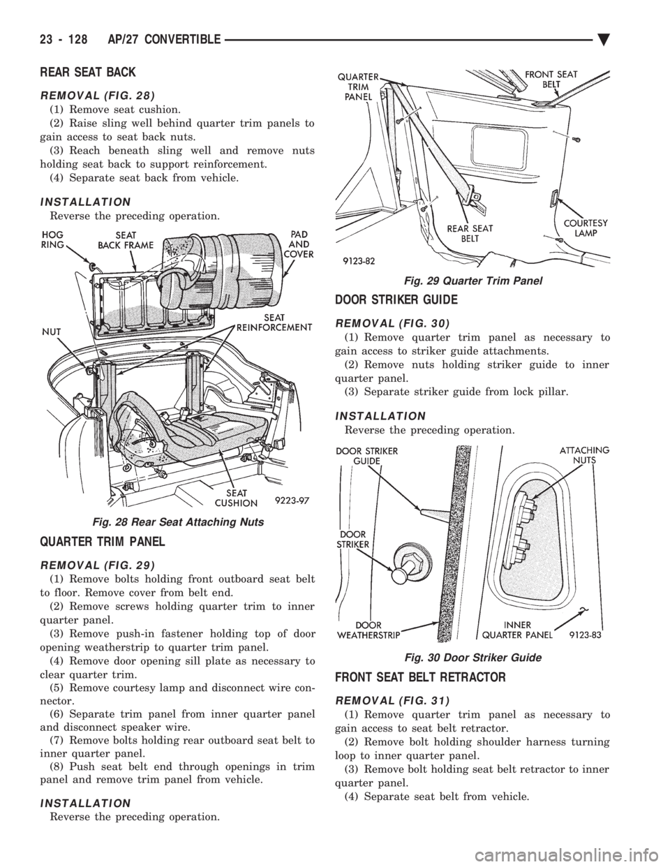
REAR SEAT BACK
REMOVAL (FIG. 28)
(1) Remove seat cushion.
(2) Raise sling well behind quarter trim panels to
gain access to seat back nuts. (3) Reach beneath sling well and remove nuts
holding seat back to support reinforcement. (4) Separate seat back from vehicle.
INSTALLATION
Reverse the preceding operation.
QUARTER TRIM PANEL
REMOVAL (FIG. 29)
(1) Remove bolts holding front outboard seat belt
to floor. Remove cover from belt end. (2) Remove screws holding quarter trim to inner
quarter panel. (3) Remove push-in fastener holding top of door
opening weatherstrip to quarter trim panel. (4) Remove door opening sill plate as necessary to
clear quarter trim. (5) Remove courtesy lamp and disconnect wire con-
nector. (6) Separate trim panel from inner quarter panel
and disconnect speaker wire. (7) Remove bolts holding rear outboard seat belt to
inner quarter panel. (8) Push seat belt end through openings in trim
panel and remove trim panel from vehicle.
INSTALLATION
Reverse the preceding operation.
DOOR STRIKER GUIDE
REMOVAL (FIG. 30)
(1) Remove quarter trim panel as necessary to
gain access to striker guide attachments. (2) Remove nuts holding striker guide to inner
quarter panel. (3) Separate striker guide from lock pillar.
INSTALLATION
Reverse the preceding operation.
FRONT SEAT BELT RETRACTOR
REMOVAL (FIG. 31)
(1) Remove quarter trim panel as necessary to
gain access to seat belt retractor. (2) Remove bolt holding shoulder harness turning
loop to inner quarter panel. (3) Remove bolt holding seat belt retractor to inner
quarter panel. (4) Separate seat belt from vehicle.
Fig. 28 Rear Seat Attaching Nuts
Fig. 29 Quarter Trim Panel
Fig. 30 Door Striker Guide
23 - 128 AP/27 CONVERTIBLE Ä
Page 2287 of 2438
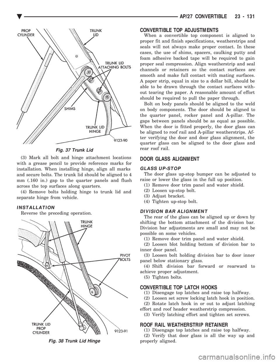
(3) Mark all bolt and hinge attachment locations
with a grease pencil to provide reference marks for
installation. When installing hinge, align all marks
and secure bolts. The trunk lid should be aligned to 4
mm (.160 in.) gap to the quarter panels and flush
across the top surfaces along quarters. (4) Remove bolts holding hinge to trunk lid and
separate hinge from vehicle.
INSTALLATION
Reverse the preceding operation.
CONVERTIBLE TOP ADJUSTMENTS
When a convertible top component is aligned to
proper fit and finish specifications, weatherstrips and
seals will not always make proper contact. In these
cases, the use of shims, spacers, caulking putty and
foam adhesive backed tape will be required to gain
proper seal compression. Align weatherstrip and seal
channels or retainers so the contact surfaces are
smooth and make full contact with mating surfaces.
A paper strip, equal in size to a dollar bill, should be
able to be drawn through the contact surfaces with-
out tearing the paper. A reasonable amount of effort
should be required to pull the paper through. Bolt on body panels should be aligned to the weld
on body components. The door should be aligned to
the quarter panel, rocker panel and A-pillar. The
gaps between panels should be as equal as possible.
When the door is fitted properly, the door glass can
be aligned to roof rail and A-pillar weatherstrips. Af-
ter verifying the door and door glass alignment, the
quarter glass can be aligned to the door glass and
rear roof rail.
DOOR GLASS ALIGNMENT
GLASS UP-STOP
The door glass up-stop bumper can be adjusted to
raise or lower the glass in the full up position. (1) Remove door trim panel and water shield.
(2) Loosen up-stop bolt.
(3) Adjust bracket.
(4) Tighten up-stop bolt.
DIVISION BAR ALIGNMENT
The rear of the glass can be aligned up or down by
shifting the bottom attachment of the division bar.
Division bar adjustments are small and may not be
possible on some vehicles. (1) Remove door trim panel and water shield.
(2) Loosen blot holding bottom of division bar to
inner door panel. (3) Loosen bolt holding division bar to door inner
panel below stationary glass. (4) Shift division bar forward or rearward to
achieve proper adjustment. (5) Tighten bolts.
CONVERTIBLE TOP LATCH HOOKS
(1) Disengage top latches and raise top halfway.
(2) Loosen set screw locking latch hook in position.
(2) Rotate latch hook in or out to adjust latching
effort and roof header weatherstrip compression. (3) Verify latching effort and tighten set screws.
ROOF RAIL WEATHERSTRIP RETAINER
(1) Disengage top latches and raise top halfway.
(2) Verify that door glass is all the way up and
properly aligned.
Fig. 37 Trunk Lid
Fig. 38 Trunk Lid Hinge
Ä AP/27 CONVERTIBLE 23 - 131
Page 2293 of 2438
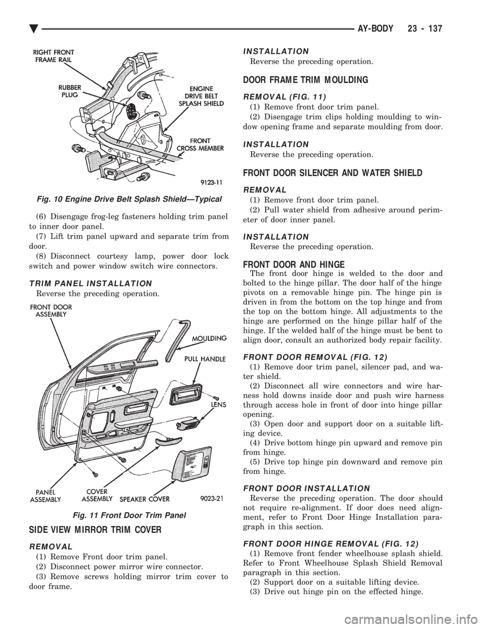
(6) Disengage frog-leg fasteners holding trim panel
to inner door panel. (7) Lift trim panel upward and separate trim from
door. (8) Disconnect courtesy lamp, power door lock
switch and power window switch wire connectors.
TRIM PANEL INSTALLATION
Reverse the preceding operation.
SIDE VIEW MIRROR TRIM COVER
REMOVAL
(1) Remove Front door trim panel.
(2) Disconnect power mirror wire connector.
(3) Remove screws holding mirror trim cover to
door frame.
INSTALLATION
Reverse the preceding operation.
DOOR FRAME TRIM MOULDING
REMOVAL (FIG. 11)
(1) Remove front door trim panel.
(2) Disengage trim clips holding moulding to win-
dow opening frame and separate moulding from door.
INSTALLATION
Reverse the preceding operation.
FRONT DOOR SILENCER AND WATER SHIELD
REMOVAL
(1) Remove front door trim panel.
(2) Pull water shield from adhesive around perim-
eter of door inner panel.
INSTALLATION
Reverse the preceding operation.
FRONT DOOR AND HINGE
The front door hinge is welded to the door and
bolted to the hinge pillar. The door half of the hinge
pivots on a removable hinge pin. The hinge pin is
driven in from the bottom on the top hinge and from
the top on the bottom hinge. All adjustments to the
hinge are performed on the hinge pillar half of the
hinge. If the welded half of the hinge must be bent to
align door, consult an authorized body repair facility.
FRONT DOOR REMOVAL (FIG. 12)
(1) Remove door trim panel, silencer pad, and wa-
ter shield. (2) Disconnect all wire connectors and wire har-
ness hold downs inside door and push wire harness
through access hole in front of door into hinge pillar
opening. (3) Open door and support door on a suitable lift-
ing device. (4) Drive bottom hinge pin upward and remove pin
from hinge. (5) Drive top hinge pin downward and remove pin
from hinge.
FRONT DOOR INSTALLATION
Reverse the preceding operation. The door should
not require re-alignment. If door does need align-
ment, refer to Front Door Hinge Installation para-
graph in this section.
FRONT DOOR HINGE REMOVAL (FIG. 12)
(1) Remove front fender wheelhouse splash shield.
Refer to Front Wheelhouse Splash Shield Removal
paragraph in this section. (2) Support door on a suitable lifting device.
(3) Drive out hinge pin on the effected hinge.
Fig. 10 Engine Drive Belt Splash ShieldÐTypical
Fig. 11 Front Door Trim Panel
Ä AY-BODY 23 - 137
Page 2294 of 2438
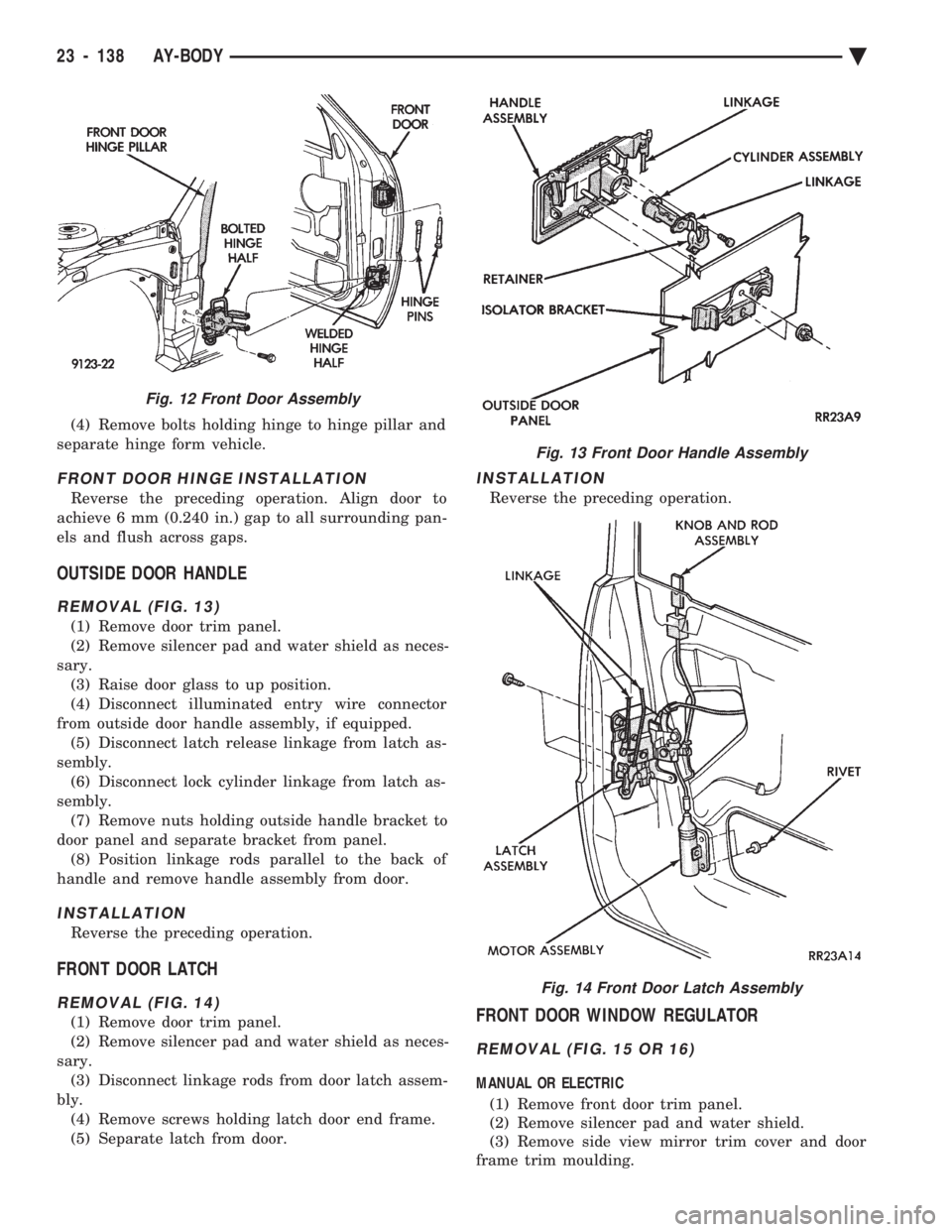
(4) Remove bolts holding hinge to hinge pillar and
separate hinge form vehicle.
FRONT DOOR HINGE INSTALLATION
Reverse the preceding operation. Align door to
achieve 6 mm (0.240 in.) gap to all surrounding pan-
els and flush across gaps.
OUTSIDE DOOR HANDLE
REMOVAL (FIG. 13)
(1) Remove door trim panel.
(2) Remove silencer pad and water shield as neces-
sary. (3) Raise door glass to up position.
(4) Disconnect illuminated entry wire connector
from outside door handle assembly, if equipped. (5) Disconnect latch release linkage from latch as-
sembly. (6) Disconnect lock cylinder linkage from latch as-
sembly. (7) Remove nuts holding outside handle bracket to
door panel and separate bracket from panel. (8) Position linkage rods parallel to the back of
handle and remove handle assembly from door.
INSTALLATION
Reverse the preceding operation.
FRONT DOOR LATCH
REMOVAL (FIG. 14)
(1) Remove door trim panel.
(2) Remove silencer pad and water shield as neces-
sary. (3) Disconnect linkage rods from door latch assem-
bly. (4) Remove screws holding latch door end frame.
(5) Separate latch from door.
INSTALLATION
Reverse the preceding operation.
FRONT DOOR WINDOW REGULATOR
REMOVAL (FIG. 15 OR 16)
MANUAL OR ELECTRIC
(1) Remove front door trim panel.
(2) Remove silencer pad and water shield.
(3) Remove side view mirror trim cover and door
frame trim moulding.
Fig. 12 Front Door Assembly
Fig. 13 Front Door Handle Assembly
Fig. 14 Front Door Latch Assembly
23 - 138 AY-BODY Ä
Page 2314 of 2438
backed off, immediately point the end of hose toward
floor, as possibly trapped refrigerant in the hose will
be released.(e) Install service port cap.
DISCHARGE (HIGH PRESSURE) GAUGE CONNECTION (1) Remove the service port cap from the 1/4 in.
service port. (2) Check all valves on the equipment being used to
verify they are closed. (3) Inspect the hose gasket in the service port con-
nector at the end of the (RED) hose. If the gasket is
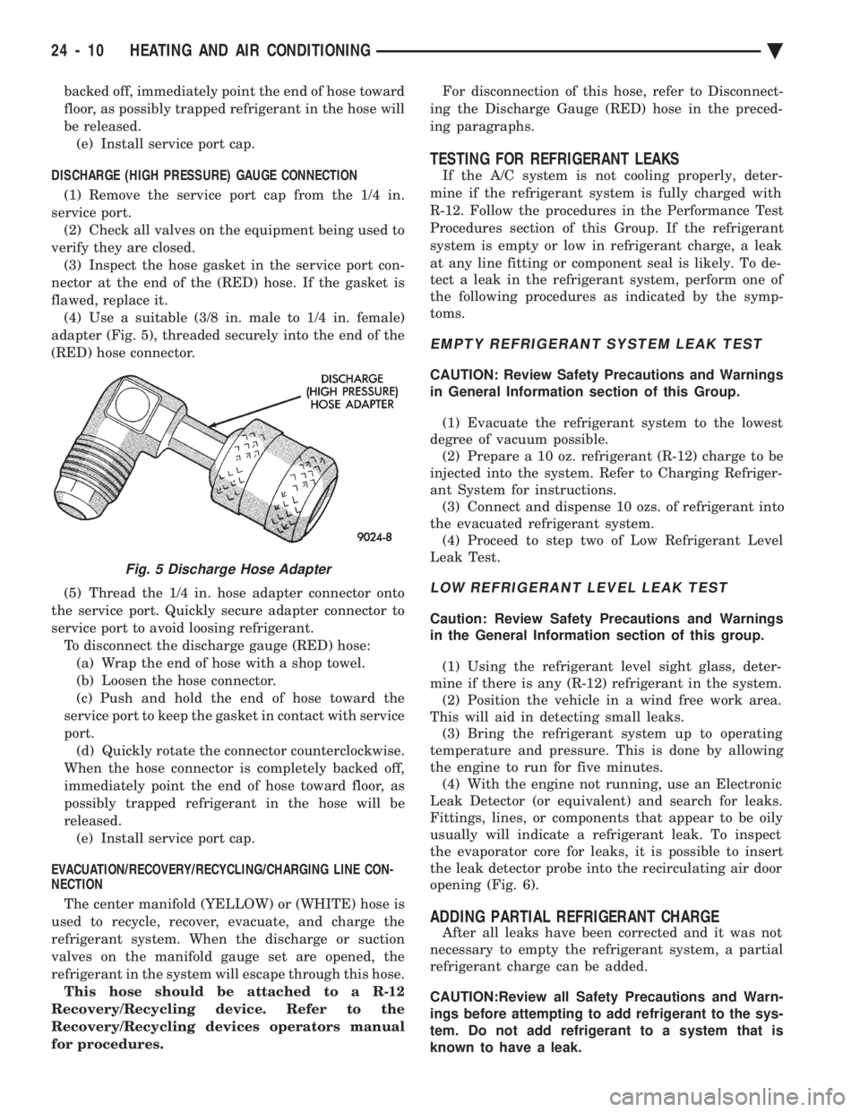
flawed, replace it. (4) Use a suitable (3/8 in. male to 1/4 in. female)
adapter (Fig. 5), threaded securely into the end of the
(RED) hose connector.
(5) Thread the 1/4 in. hose adapter connector onto
the service port. Quickly secure adapter connector to
service port to avoid loosing refrigerant. To disconnect the discharge gauge (RED) hose:(a) Wrap the end of hose with a shop towel.
(b) Loosen the hose connector.
(c) Push and hold the end of hose toward the
service port to keep the gasket in contact with service
port. (d) Quickly rotate the connector counterclockwise.
When the hose connector is completely backed off,
immediately point the end of hose toward floor, as
possibly trapped refrigerant in the hose will be
released. (e) Install service port cap.
EVACUATION/RECOVERY/RECYCLING/CHARGING LINE CON-
NECTION
The center manifold (YELLOW) or (WHITE) hose is
used to recycle, recover, evacuate, and charge the
refrigerant system. When the discharge or suction
valves on the manifold gauge set are opened, the
refrigerant in the system will escape through this hose. This hose should be attached to a R-12
Recovery/Recycling device. Refer to the
Recovery/Recycling devices operators manual
for procedures. For disconnection of this hose, refer to Disconnect-
ing the Discharge Gauge (RED) hose in the preced-
ing paragraphs.
TESTING FOR REFRIGERANT LEAKS
If the A/C system is not cooling properly, deter-
mine if the refrigerant system is fully charged with
R-12. Follow the procedures in the Performance Test
Procedures section of this Group. If the refrigerant
system is empty or low in refrigerant charge, a leak
at any line fitting or component seal is likely. To de-
tect a leak in the refrigerant system, perform one of
the following procedures as indicated by the symp-
toms.
EMPTY REFRIGERANT SYSTEM LEAK TEST
CAUTION: Review Safety Precautions and Warnings
in General Information section of this Group.
(1) Evacuate the refrigerant system to the lowest
degree of vacuum possible. (2) Prepare a 10 oz. refrigerant (R-12) charge to be
injected into the system. Refer to Charging Refriger-
ant System for instructions. (3) Connect and dispense 10 ozs. of refrigerant into
the evacuated refrigerant system. (4) Proceed to step two of Low Refrigerant Level
Leak Test.
LOW REFRIGERANT LEVEL LEAK TEST
Caution: Review Safety Precautions and Warnings
in the General Information section of this group.
(1) Using the refrigerant level sight glass, deter-
mine if there is any (R-12) refrigerant in the system. (2) Position the vehicle in a wind free work area.
This will aid in detecting small leaks. (3) Bring the refrigerant system up to operating
temperature and pressure. This is done by allowing
the engine to run for five minutes. (4) With the engine not running, use an Electronic
Leak Detector (or equivalent) and search for leaks.
Fittings, lines, or components that appear to be oily
usually will indicate a refrigerant leak. To inspect
the evaporator core for leaks, it is possible to insert
the leak detector probe into the recirculating air door
opening (Fig. 6).
ADDING PARTIAL REFRIGERANT CHARGE
After all leaks have been corrected and it was not
necessary to empty the refrigerant system, a partial
refrigerant charge can be added.
CAUTION:Review all Safety Precautions and Warn-
ings before attempting to add refrigerant to the sys-
tem. Do not add refrigerant to a system that is
known to have a leak.
Fig. 5 Discharge Hose Adapter
24 - 10 HEATING AND AIR CONDITIONING Ä
Page 2351 of 2438
COMPONENT SERVICE PROCEDURES INDEX
page page
Air Distribution Duct ...................... 50
Air Distribution Duct ...................... 52
Ambient Switch .......................... 47
Blend-Air Door .......................... 64
Blower Motor ............................ 58
Blower Motor Wheel Assembly .............. 58
Blower Resistor Block ..................... 49
Condensate Drain Tube ................... 64
Condenser Assembly ...................... 57
Condenser Fan Control Switch .............. 47
Defroster Duct ........................... 51
Defroster Duct Adapter .................... 51
Defroster Ducts/Demister Ducts and Hoses ..... 52
Differential Pressure Cut-Out Switch Diagnosis . . 48
Evaporator Coil .......................... 64 Expansion Valve
......................... 55
Filter-Drier Assembly ...................... 57
Fin-Sensing Cycling Clutch Switch ............ 53
Heater Core ............................ 64
Heater Hoses ........................... 51
Heater-A/C Unit AssemblyÐRemoval and Installation ............................ 61
Heater-A/C Unit Recondition ................ 63
Low or Differential Pressure Cut-Off Switch ..... 54
Temperature Control CableÐAA,AP,AG and AJ Models ............................ 49
Temperature Control CableÐAC/AY Models .... 48
Vacuum ActuatorÐFresh/Recirc Door ......... 50
Vacuum ActuatorsÐMode Doors ............. 52
AMBIENT SWITCH
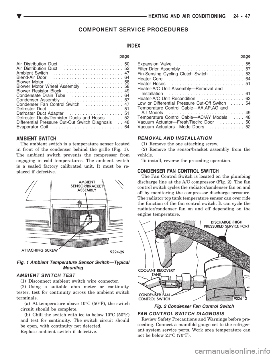
The ambient switch is a temperature sensor located
in front of the condenser behind the grille (Fig. 1).
The ambient switch prevents the compressor from
engaging in cold temperatures. The ambient switch
is a sealed factory calibrated unit. It must be re-
placed if defective.
AMBIENT SWITCH TEST
(1) Disconnect ambient switch wire connector.
(2) Using a suitable ohm meter or continuity
tester, test for continuity across the ambient switch
terminals. (a) At temperature above 10ÉC (50ÉF), the switch
circuit should be complete. (b) Chill the switch with ice to below 10ÉC (50ÉF)
and test for continuity. The switch circuit should
be open, with continuity not detected.
Replace ambient switch if defective.
REMOVAL AND INSTALLATION
(1) Remove the one attaching screw.
(2) Remove the sensor/bracket assembly from the
vehicle. To install, reverse the preceding operation.
CONDENSER FAN CONTROL SWITCH
The Fan Control Switch is located on the plumbing
discharge line at the A/C compressor (Fig. 2). The fan
control switch cycles the radiator/condenser fan on and
off by monitoring the compressor discharge pressure.
The radiator top tank temperature sensor can over ride
the function of the fan control switch. It can cycle the
radiator/condenser fan on and off depending on the
engine temperature.
FAN CONTROL SWITCH DIAGNOSIS
Review Safety Precautions and Warnings before pro-
ceeding. Connect a manifold gauge set to the refriger-
ant system service ports. Work area temperature can
not be below 21ÉC (70ÉF).
Fig. 1 Ambient Temperature Sensor SwitchÐTypical Mounting
Fig. 2 Condenser Fan Control Switch
Ä HEATING AND AIR CONDITIONING 24 - 47