1993 CHEVROLET PLYMOUTH ACCLAIM door lock
[x] Cancel search: door lockPage 2225 of 2438
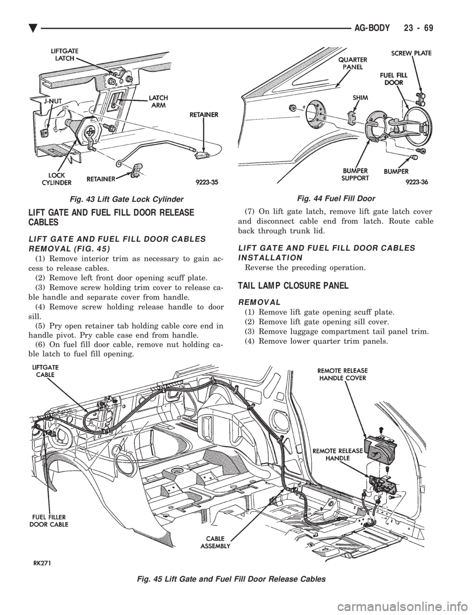
LIFT GATE AND FUEL FILL DOOR RELEASE
CABLES
LIFT GATE AND FUEL FILL DOOR CABLES
REMOVAL (FIG. 45)
(1) Remove interior trim as necessary to gain ac-
cess to release cables. (2) Remove left front door opening scuff plate.
(3) Remove screw holding trim cover to release ca-
ble handle and separate cover from handle. (4) Remove screw holding release handle to door
sill. (5) Pry open retainer tab holding cable core end in
handle pivot. Pry cable case end from handle. (6) On fuel fill door cable, remove nut holding ca-
ble latch to fuel fill opening. (7) On lift gate latch, remove lift gate latch cover
and disconnect cable end from latch. Route cable
back through trunk lid.
LIFT GATE AND FUEL FILL DOOR CABLES INSTALLATION
Reverse the preceding operation.
TAIL LAMP CLOSURE PANEL
REMOVAL
(1) Remove lift gate opening scuff plate.
(2) Remove lift gate opening sill cover.
(3) Remove luggage compartment tail panel trim.
(4) Remove lower quarter trim panels.
Fig. 45 Lift Gate and Fuel Fill Door Release Cables
Fig. 43 Lift Gate Lock CylinderFig. 44 Fuel Fill Door
Ä AG-BODY 23 - 69
Page 2227 of 2438
AJ-VEHICLE BODY COMPONENT SERVICE INDEX
page page
A-Pillar and Roof Rail Mouldings ............. 77
Cowl Cover ............................. 73
Cowl Panel Trim and Scuff Plates ............ 77
Door Glass ............................. 76
Door Glass Lift Plate and Guide Post ......... 76
Door Latch ............................. 75
Door Trim Panel ......................... 74
Floor Carpet ............................ 80
Front Center Console ..................... 79
Front Door and Hinge ..................... 75
Front Door Silencer and Water Shield ......... 74
Front End Splash Shields .................. 73
Front Seat Belts ......................... 78
Front Seats ............................. 78
Fuel Fill Door ........................... 84
Glass Run WeatherstripÐAJ-21 Body ......... 76
Grille .................................. 71
Grille Header Molding ..................... 71
Grille Opening Panel ...................... 71
Head Lining ............................. 81
Hood and Hinges ........................ 72
Hood Latch and Release Cable .............. 72
Inside Latch Release Handle ................ 76 Lower Grille
............................. 71
Outside Door Latch Release Handle .......... 76
Overhead Console ........................ 80
Power Door Lock Actuator .................. 76
Quarter Extension Trim Panel ............... 77
Quarter Glass Module ..................... 85
Quarter Trim Panel ....................... 77
Rear Seat Belts .......................... 78
Rear Seats ............................. 79
Rear Shelf Trim Panel ..................... 78
Rear Window Glass ...................... 81
Sun Roof Air Deflector .................... 81
Sun Roof Drain Tubes .................... 81
Sun Roof Weatherstrip .................... 81
Trunk Lid .............................. 82
Trunk Lid and Fuel Fill Door Release Cables . . . 83
Trunk Lid Hinge ......................... 82
Trunk Lid Latch .......................... 83
Trunk Lid Lock .......................... 83
Trunk Lid Luggage Rack ................... 83
Trunk Lid Torsion Bar ..................... 83
Trunk Opening Weatherstrip ................ 83
Window Regulator ........................ 75
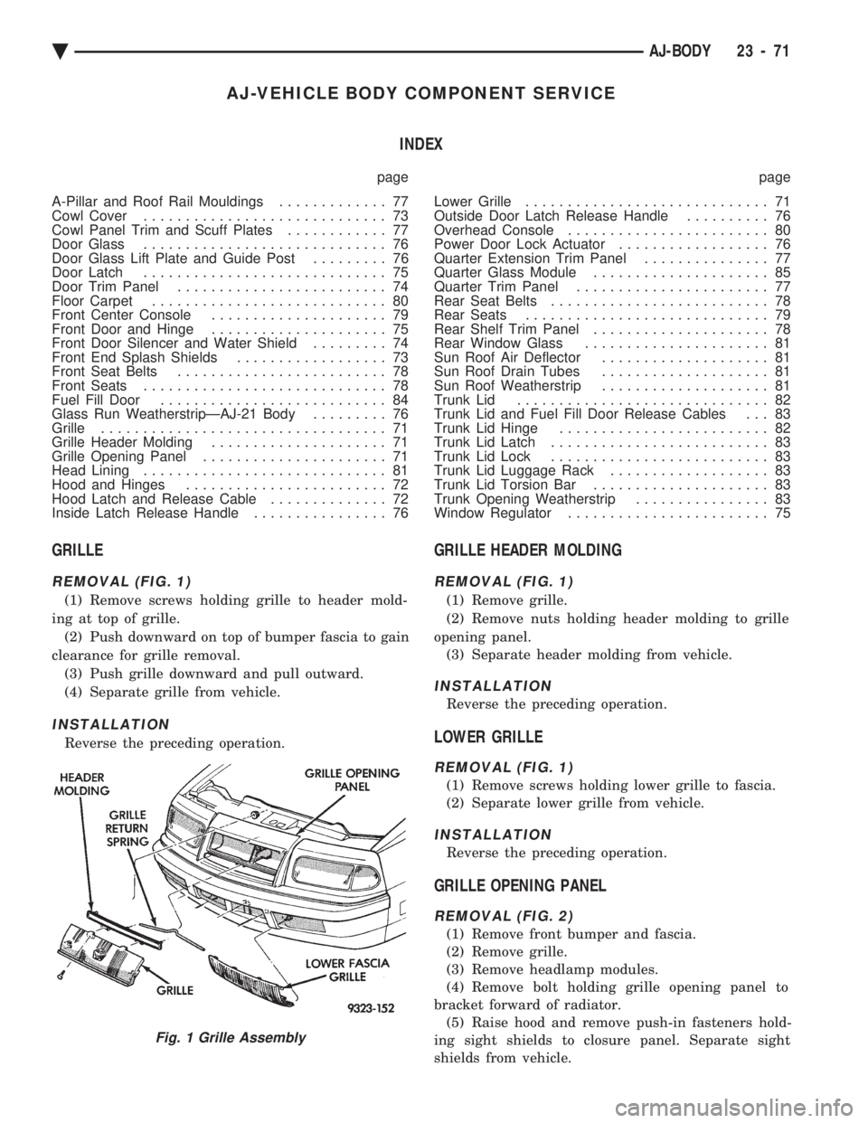
GRILLE
REMOVAL (FIG. 1)
(1) Remove screws holding grille to header mold-
ing at top of grille. (2) Push downward on top of bumper fascia to gain
clearance for grille removal. (3) Push grille downward and pull outward.
(4) Separate grille from vehicle.
INSTALLATION
Reverse the preceding operation.
GRILLE HEADER MOLDING
REMOVAL (FIG. 1)
(1) Remove grille.
(2) Remove nuts holding header molding to grille
opening panel. (3) Separate header molding from vehicle.
INSTALLATION
Reverse the preceding operation.
LOWER GRILLE
REMOVAL (FIG. 1)
(1) Remove screws holding lower grille to fascia.
(2) Separate lower grille from vehicle.
INSTALLATION
Reverse the preceding operation.
GRILLE OPENING PANEL
REMOVAL (FIG. 2)
(1) Remove front bumper and fascia.
(2) Remove grille.
(3) Remove headlamp modules.
(4) Remove bolt holding grille opening panel to
bracket forward of radiator. (5) Raise hood and remove push-in fasteners hold-
ing sight shields to closure panel. Separate sight
shields from vehicle.
Fig. 1 Grille Assembly
Ä AJ-BODY 23 - 71
Page 2230 of 2438
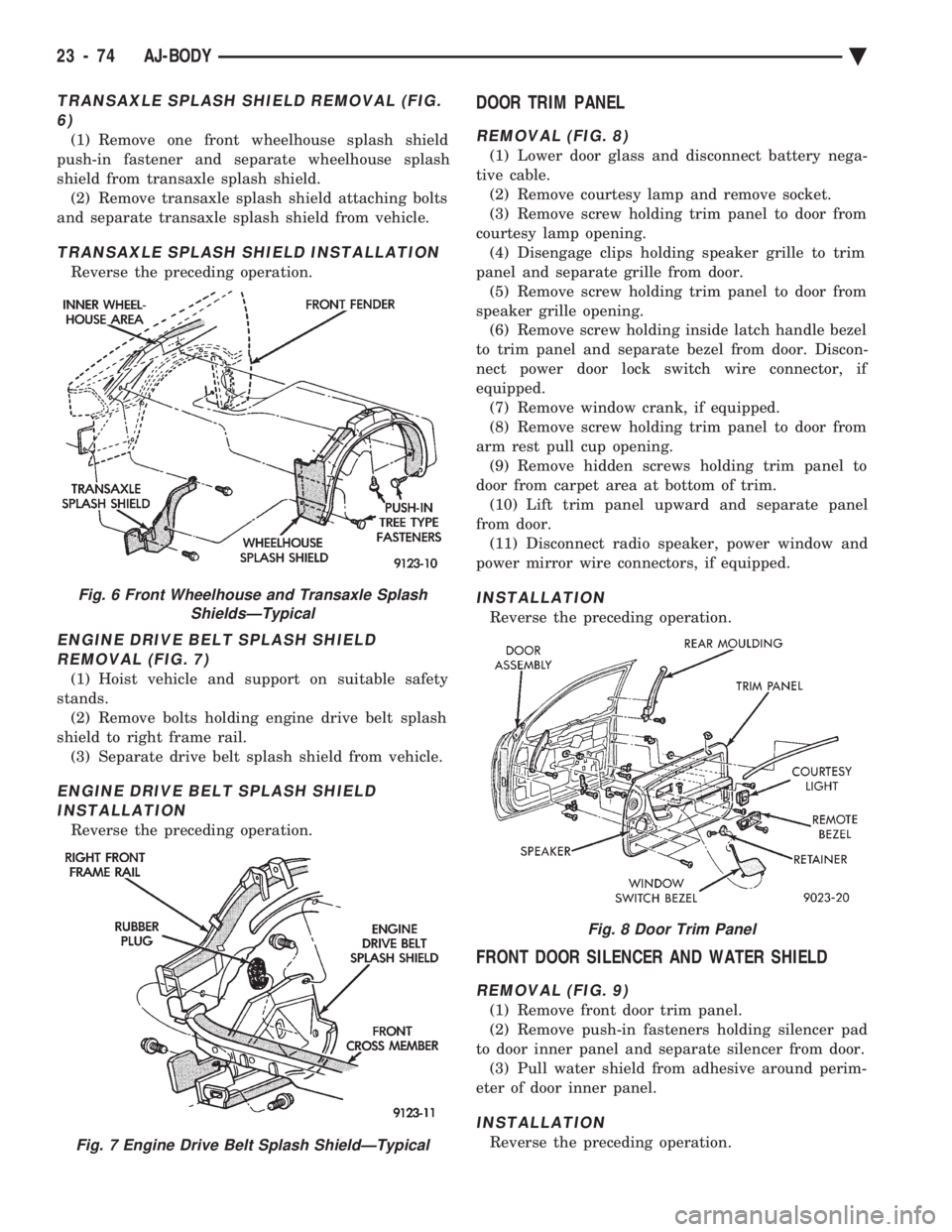
TRANSAXLE SPLASH SHIELD REMOVAL (FIG. 6)
(1) Remove one front wheelhouse splash shield
push-in fastener and separate wheelhouse splash
shield from transaxle splash shield. (2) Remove transaxle splash shield attaching bolts
and separate transaxle splash shield from vehicle.
TRANSAXLE SPLASH SHIELD INSTALLATION
Reverse the preceding operation.
ENGINE DRIVE BELT SPLASH SHIELD REMOVAL (FIG. 7)
(1) Hoist vehicle and support on suitable safety
stands. (2) Remove bolts holding engine drive belt splash
shield to right frame rail. (3) Separate drive belt splash shield from vehicle.
ENGINE DRIVE BELT SPLASH SHIELDINSTALLATION
Reverse the preceding operation.
DOOR TRIM PANEL
REMOVAL (FIG. 8)
(1) Lower door glass and disconnect battery nega-
tive cable. (2) Remove courtesy lamp and remove socket.
(3) Remove screw holding trim panel to door from
courtesy lamp opening. (4) Disengage clips holding speaker grille to trim
panel and separate grille from door. (5) Remove screw holding trim panel to door from
speaker grille opening. (6) Remove screw holding inside latch handle bezel
to trim panel and separate bezel from door. Discon-
nect power door lock switch wire connector, if
equipped. (7) Remove window crank, if equipped.
(8) Remove screw holding trim panel to door from
arm rest pull cup opening. (9) Remove hidden screws holding trim panel to
door from carpet area at bottom of trim. (10) Lift trim panel upward and separate panel
from door. (11) Disconnect radio speaker, power window and
power mirror wire connectors, if equipped.
INSTALLATION
Reverse the preceding operation.
FRONT DOOR SILENCER AND WATER SHIELD
REMOVAL (FIG. 9)
(1) Remove front door trim panel.
(2) Remove push-in fasteners holding silencer pad
to door inner panel and separate silencer from door. (3) Pull water shield from adhesive around perim-
eter of door inner panel.
INSTALLATION
Reverse the preceding operation.
Fig. 6 Front Wheelhouse and Transaxle Splash ShieldsÐTypical
Fig. 7 Engine Drive Belt Splash ShieldÐTypical
Fig. 8 Door Trim Panel
23 - 74 AJ-BODY Ä
Page 2232 of 2438
DOOR GLASS
REMOVAL
(1) Remove door trim panel.
(2) Remove silencer and water shield.
(3) Raise door glass 100 mm (4 in.) from down po-
sition. (4) Disconnect battery negative cable if equipped
with power windows. (5) Loosen bolts holding glass stabilizers and guide
hook receiver to top of inner door frame. (6) Remove nuts holding door glass to lift plate.
(7) Separate glass from lift plate and lift glass up-
ward from opening at top of door.
INSTALLATION
Reverse the preceding operation.
DOOR GLASS LIFT PLATE AND GUIDE POST
REMOVAL
(1) Remove door trim panel.
(2) Remove silencer and water shield.
(3) Raise door glass 100 mm (4 in.) from down po-
sition. (4) Disconnect battery negative cable if equipped
with power windows. (5) Remove nuts holding door glass to lift plate
and separate glass from lift plate. Allow glass to
slide downward to the bottom of door. (6) Remove bolts (nuts on AJ-27 body) holding
guide post to inner door panel. (7) Separate lift plate channel from regulator lift
roller. (8) Remove lift plate and guide assemble from door
through access hole in inner door panel.
INSTALLATION
Reverse the preceding operation.
GLASS RUN WEATHERSTRIPÐAJ-21 BODY
REMOVAL
(1) Remove door trim panel.
(2) Remove silencer and water shield as necessary.
(3) Remove side view mirror cover.
(4) Pull glass run weatherstrip from door frame
channel.
INSTALLATION
Reverse the preceding operation.
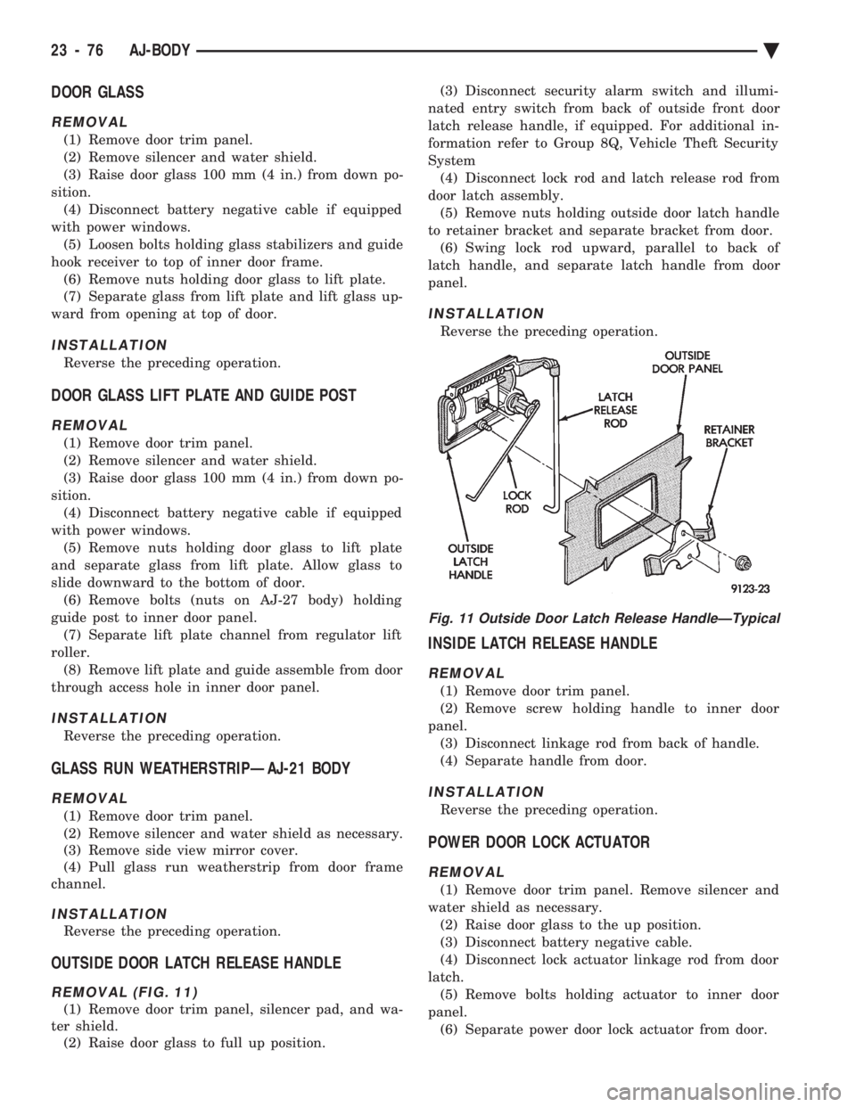
OUTSIDE DOOR LATCH RELEASE HANDLE
REMOVAL (FIG. 11)
(1) Remove door trim panel, silencer pad, and wa-
ter shield. (2) Raise door glass to full up position. (3) Disconnect security alarm switch and illumi-
nated entry switch from back of outside front door
latch release handle, if equipped. For additional in-
formation refer to Group 8Q, Vehicle Theft Security
System (4) Disconnect lock rod and latch release rod from
door latch assembly. (5) Remove nuts holding outside door latch handle
to retainer bracket and separate bracket from door. (6) Swing lock rod upward, parallel to back of
latch handle, and separate latch handle from door
panel.
INSTALLATION
Reverse the preceding operation.
INSIDE LATCH RELEASE HANDLE
REMOVAL
(1) Remove door trim panel.
(2) Remove screw holding handle to inner door
panel. (3) Disconnect linkage rod from back of handle.
(4) Separate handle from door.
INSTALLATION
Reverse the preceding operation.
POWER DOOR LOCK ACTUATOR
REMOVAL
(1) Remove door trim panel. Remove silencer and
water shield as necessary. (2) Raise door glass to the up position.
(3) Disconnect battery negative cable.
(4) Disconnect lock actuator linkage rod from door
latch. (5) Remove bolts holding actuator to inner door
panel. (6) Separate power door lock actuator from door.
Fig. 11 Outside Door Latch Release HandleÐTypical
23 - 76 AJ-BODY Ä
Page 2239 of 2438
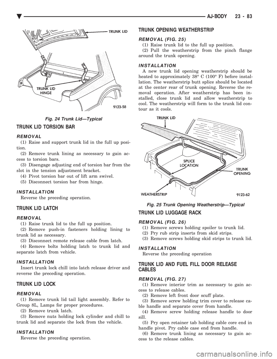
TRUNK LID TORSION BAR
REMOVAL
(1) Raise and support trunk lid in the full up posi-
tion. (2) Remove trunk lining as necessary to gain ac-
cess to torsion bars. (3) Disengage adjusting end of torsion bar from the
slot in the tension adjustment bracket. (4) Pivot torsion bar out of lift arm swivel.
(5) Disconnect torsion bar from hinge.
INSTALLATION
Reverse the preceding operation.
TRUNK LID LATCH
REMOVAL
(1) Raise trunk lid to the full up position.
(2) Remove push-in fasteners holding lining to
trunk lid as necessary. (3) Disconnect remote release cable from latch.
(4) Remove bolts holding latch to trunk lid and
separate latch from vehicle.
INSTALLATION
Insert trunk lock chill into latch release driver and
reverse the preceding operation.
TRUNK LID LOCK
REMOVAL
(1) Remove trunk lid tail light assembly. Refer to
Group 8L, Lamps for proper procedures. (2) Remove trunk latch.
(3) Remove nuts holding lock cylinder and chill to
trunk lid and separate the lock from the vehicle.
INSTALLATION
Reverse the preceding operation.
TRUNK OPENING WEATHERSTRIP
REMOVAL (FIG. 25)
(1) Raise trunk lid to the full up position.
(2) Pull the weatherstrip from the pinch flange
around the trunk opening.
INSTALLATION
A new trunk lid opening weatherstrip should be
heated to approximately 38É C (100É F) before instal-
lation. The weatherstrip butt splice should be located
at the center rear of trunk opening. Reverse the re-
moval operation. After weatherstrip has been in-
stalled, close trunk lid and allow weatherstrip to
cool. The weatherstrip will form to the trunk lid con-
tour as it cools.
TRUNK LID LUGGAGE RACK
REMOVAL (FIG. 26)
(1) Remove screws holding spoiler to trunk lid.
(2) Pry rub strip inserts from skid strips.
(3) Remove screws holding skid strips to trunk lid.
INSTALLATION
Reverse the preceding operation
TRUNK LID AND FUEL FILL DOOR RELEASE
CABLES
REMOVAL (FIG. 27)
(1) Remove interior trim as necessary to gain ac-
cess to release cables. (2) Remove left front door scuff plate.
(3) Remove screw holding trim cover to release ca-
ble handle and separate cover from handle. (4) Remove screw holding release handle to door
sill. (5) Pry open retainer tab holding cable core end in
handle pivot. Pry cable case end from handle. (6) Remove trunk lining as necessary to gain ac-
cess to the release cables.
Fig. 24 Trunk LidÐTypical
Fig. 25 Trunk Opening WeatherstripÐTypical
Ä AJ-BODY 23 - 83
Page 2253 of 2438
AP-VEHICLE BODY COMPONENT SERVICE INDEX
page page
A-Pillar and Roof Rail Mouldings ............ 109
B-Pillar Trim PanelÐAP-44 Body ............ 109
Body Side Moulding and Applique ........... 108
Cowl Panel Trim and Scuff Plates ........... 109
Door Opening Weatherstrips ............... 107
Floor Carpet ........................... 113
Front Center Console .................... 113
Front Door and Hinge .................... 100
Front Door Belt Moulding and Weatherstrip .... 102
Front Door Glass ........................ 101
Front Door Glass Channel and Run Weatherstrip .......................... 103
Front Door Glass Run Lower Channels ....... 103
Front Door Latch ........................ 101
Front Door Side View Mirror ............... 101
Front Door Trim PanelÐAP-24/44 Body ....... 99
Front Door Water Shield .................. 100
Front Door Window Regulator/Manual ........ 103
Front Door Window Regulator/Power ......... 104
Front End Splash Shields .................. 99
Front Power Door Lock Actuator ............ 102
Front Seat BeltsÐAP-24 Body .............. 110
Front Seat BeltsÐAP-44 Body .............. 110
Front Seats ............................ 111
Grille .................................. 97
Grille Opening Panel ...................... 97
Head Lining ............................ 114
Hood and Hinges ........................ 97 Hood Latch and Release Cable
.............. 98
Lift Gate Luggage Rack ................... 116
Lift Gate Remote Release Cable ............ 115
Lower Quarter Trim PanelÐAP-44 Body ...... 109
Outside Front Door Latch Release Handle ..... 101
Outside Rear Door Latch Release Handle ..... 105
Overhead Console ....................... 113
Quarter Glass Weatherstrip ................ 108
Quarter Glass Window ................... 108
Quarter Trim PanelÐAP-44 Body ........... 109
Rear Door and Hinge .................... 104
Rear Door Belt Moulding and Weatherstrip .... 106
Rear Door Glass ........................ 106
Rear Door Glass Run Weatherstrip .......... 107
Rear Door Latch ........................ 105
Rear Door Silencer and Water Shield ........ 104
Rear Door Stationary Glass ................ 107
Rear Door Trim Panel .................... 104
Rear Door Window Regulator/Manual ........ 107
Rear Door Window Regulator/Power ......... 107
Rear Power Door Lock Actuator ............ 106
Rear Seat Belts ......................... 111
Rear Seats ............................ 112
Rear Window Glass ...................... 115
Sun Roof Air Deflector ................... 114
Sun Roof Drain Tubes .................... 115
Sun Roof Weatherstrip ................... 114
Upper Quarter Trim PanelÐAP-44 Body ...... 109
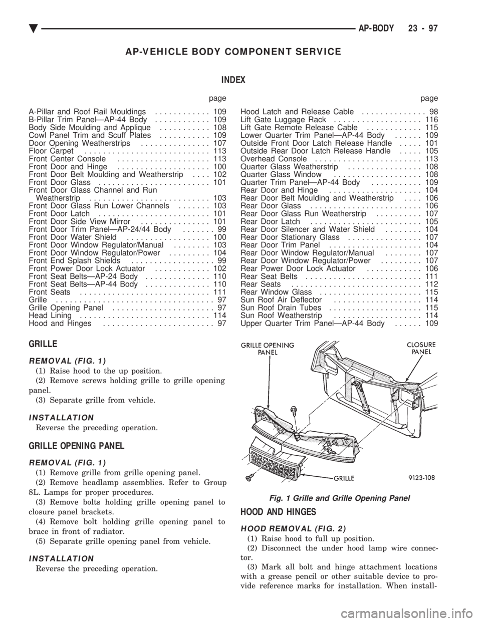
GRILLE
REMOVAL (FIG. 1)
(1) Raise hood to the up position.
(2) Remove screws holding grille to grille opening
panel. (3) Separate grille from vehicle.
INSTALLATION
Reverse the preceding operation.
GRILLE OPENING PANEL
REMOVAL (FIG. 1)
(1) Remove grille from grille opening panel.
(2) Remove headlamp assemblies. Refer to Group
8L. Lamps for proper procedures. (3) Remove bolts holding grille opening panel to
closure panel brackets. (4) Remove bolt holding grille opening panel to
brace in front of radiator. (5) Separate grille opening panel from vehicle.
INSTALLATION
Reverse the preceding operation.
HOOD AND HINGES
HOOD REMOVAL (FIG. 2)
(1) Raise hood to full up position.
(2) Disconnect the under hood lamp wire connec-
tor. (3) Mark all bolt and hinge attachment locations
with a grease pencil or other suitable device to pro-
vide reference marks for installation. When install-
Fig. 1 Grille and Grille Opening Panel
Ä AP-BODY 23 - 97
Page 2256 of 2438
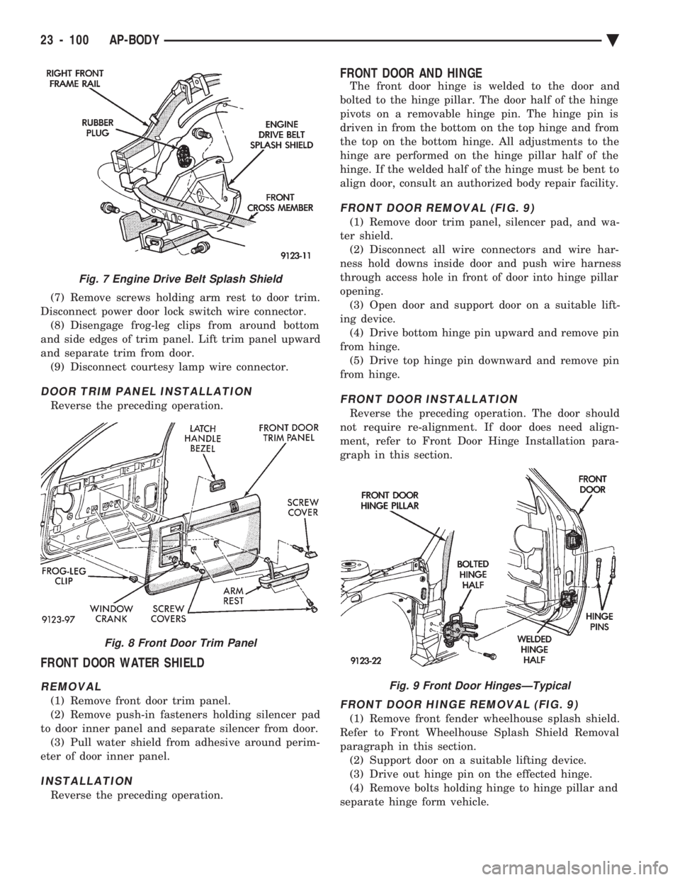
(7) Remove screws holding arm rest to door trim.
Disconnect power door lock switch wire connector. (8) Disengage frog-leg clips from around bottom
and side edges of trim panel. Lift trim panel upward
and separate trim from door. (9) Disconnect courtesy lamp wire connector.
DOOR TRIM PANEL INSTALLATION
Reverse the preceding operation.
FRONT DOOR WATER SHIELD
REMOVAL
(1) Remove front door trim panel.
(2) Remove push-in fasteners holding silencer pad
to door inner panel and separate silencer from door. (3) Pull water shield from adhesive around perim-
eter of door inner panel.
INSTALLATION
Reverse the preceding operation.
FRONT DOOR AND HINGE
The front door hinge is welded to the door and
bolted to the hinge pillar. The door half of the hinge
pivots on a removable hinge pin. The hinge pin is
driven in from the bottom on the top hinge and from
the top on the bottom hinge. All adjustments to the
hinge are performed on the hinge pillar half of the
hinge. If the welded half of the hinge must be bent to
align door, consult an authorized body repair facility.
FRONT DOOR REMOVAL (FIG. 9)
(1) Remove door trim panel, silencer pad, and wa-
ter shield. (2) Disconnect all wire connectors and wire har-
ness hold downs inside door and push wire harness
through access hole in front of door into hinge pillar
opening. (3) Open door and support door on a suitable lift-
ing device. (4) Drive bottom hinge pin upward and remove pin
from hinge. (5) Drive top hinge pin downward and remove pin
from hinge.
FRONT DOOR INSTALLATION
Reverse the preceding operation. The door should
not require re-alignment. If door does need align-
ment, refer to Front Door Hinge Installation para-
graph in this section.
FRONT DOOR HINGE REMOVAL (FIG. 9)
(1) Remove front fender wheelhouse splash shield.
Refer to Front Wheelhouse Splash Shield Removal
paragraph in this section. (2) Support door on a suitable lifting device.
(3) Drive out hinge pin on the effected hinge.
(4) Remove bolts holding hinge to hinge pillar and
separate hinge form vehicle.
Fig. 7 Engine Drive Belt Splash Shield
Fig. 8 Front Door Trim Panel
Fig. 9 Front Door HingesÐTypical
23 - 100 AP-BODY Ä
Page 2257 of 2438
FRONT DOOR HINGE INSTALLATION
Reverse the preceding operation. Align door to
achieve 6 mm (0.240 in.) gap to all surrounding pan-
els and flush across gaps.
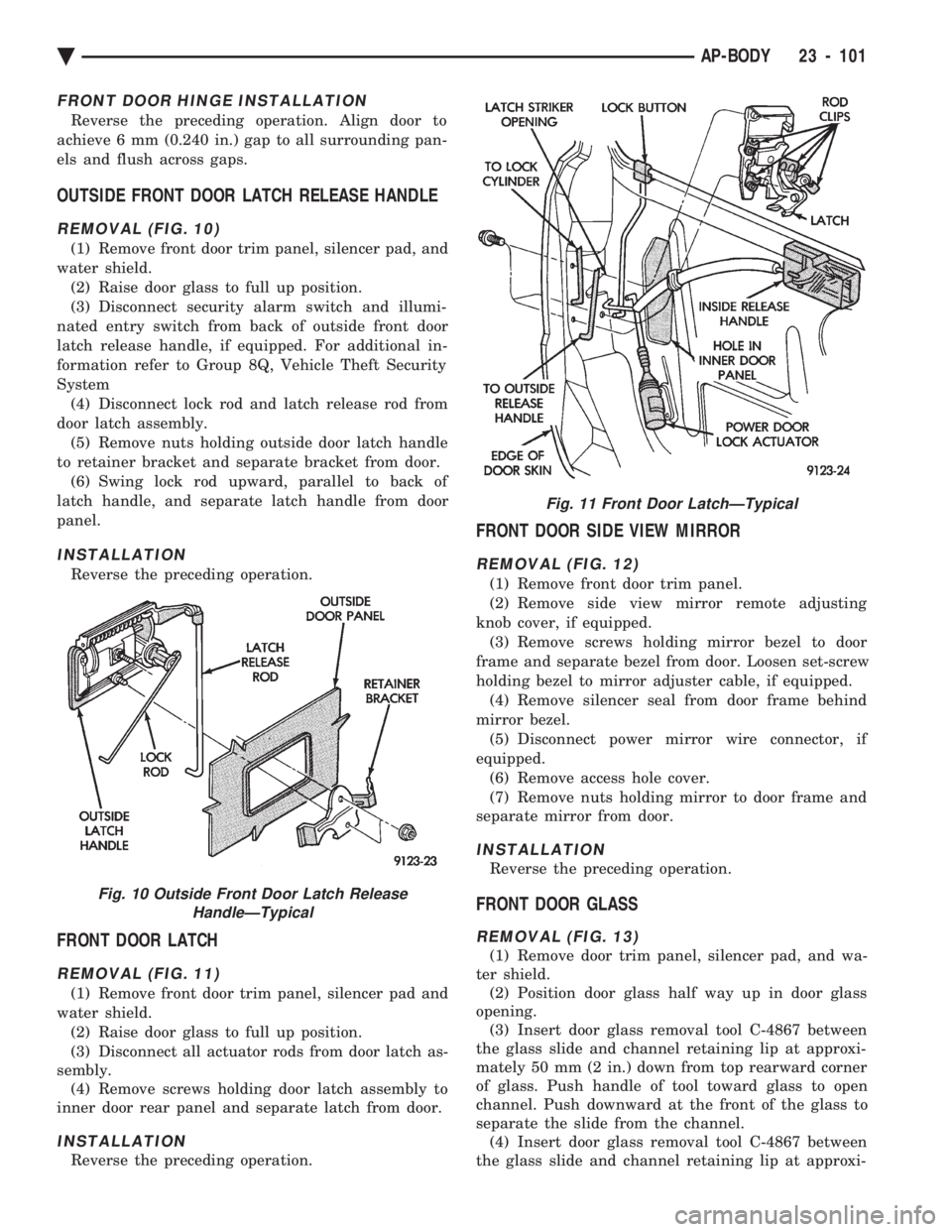
OUTSIDE FRONT DOOR LATCH RELEASE HANDLE
REMOVAL (FIG. 10)
(1) Remove front door trim panel, silencer pad, and
water shield. (2) Raise door glass to full up position.
(3) Disconnect security alarm switch and illumi-
nated entry switch from back of outside front door
latch release handle, if equipped. For additional in-
formation refer to Group 8Q, Vehicle Theft Security
System (4) Disconnect lock rod and latch release rod from
door latch assembly. (5) Remove nuts holding outside door latch handle
to retainer bracket and separate bracket from door. (6) Swing lock rod upward, parallel to back of
latch handle, and separate latch handle from door
panel.
INSTALLATION
Reverse the preceding operation.
FRONT DOOR LATCH
REMOVAL (FIG. 11)
(1) Remove front door trim panel, silencer pad and
water shield. (2) Raise door glass to full up position.
(3) Disconnect all actuator rods from door latch as-
sembly. (4) Remove screws holding door latch assembly to
inner door rear panel and separate latch from door.
INSTALLATION
Reverse the preceding operation.
FRONT DOOR SIDE VIEW MIRROR
REMOVAL (FIG. 12)
(1) Remove front door trim panel.
(2) Remove side view mirror remote adjusting
knob cover, if equipped. (3) Remove screws holding mirror bezel to door
frame and separate bezel from door. Loosen set-screw
holding bezel to mirror adjuster cable, if equipped. (4) Remove silencer seal from door frame behind
mirror bezel. (5) Disconnect power mirror wire connector, if
equipped. (6) Remove access hole cover.
(7) Remove nuts holding mirror to door frame and
separate mirror from door.
INSTALLATION
Reverse the preceding operation.
FRONT DOOR GLASS
REMOVAL (FIG. 13)
(1) Remove door trim panel, silencer pad, and wa-
ter shield. (2) Position door glass half way up in door glass
opening. (3) Insert door glass removal tool C-4867 between
the glass slide and channel retaining lip at approxi-
mately 50 mm (2 in.) down from top rearward corner
of glass. Push handle of tool toward glass to open
channel. Push downward at the front of the glass to
separate the slide from the channel. (4) Insert door glass removal tool C-4867 between
the glass slide and channel retaining lip at approxi-
Fig. 10 Outside Front Door Latch Release HandleÐTypical
Fig. 11 Front Door LatchÐTypical
Ä AP-BODY 23 - 101