1993 CHEVROLET PLYMOUTH ACCLAIM door lock
[x] Cancel search: door lockPage 2353 of 2438
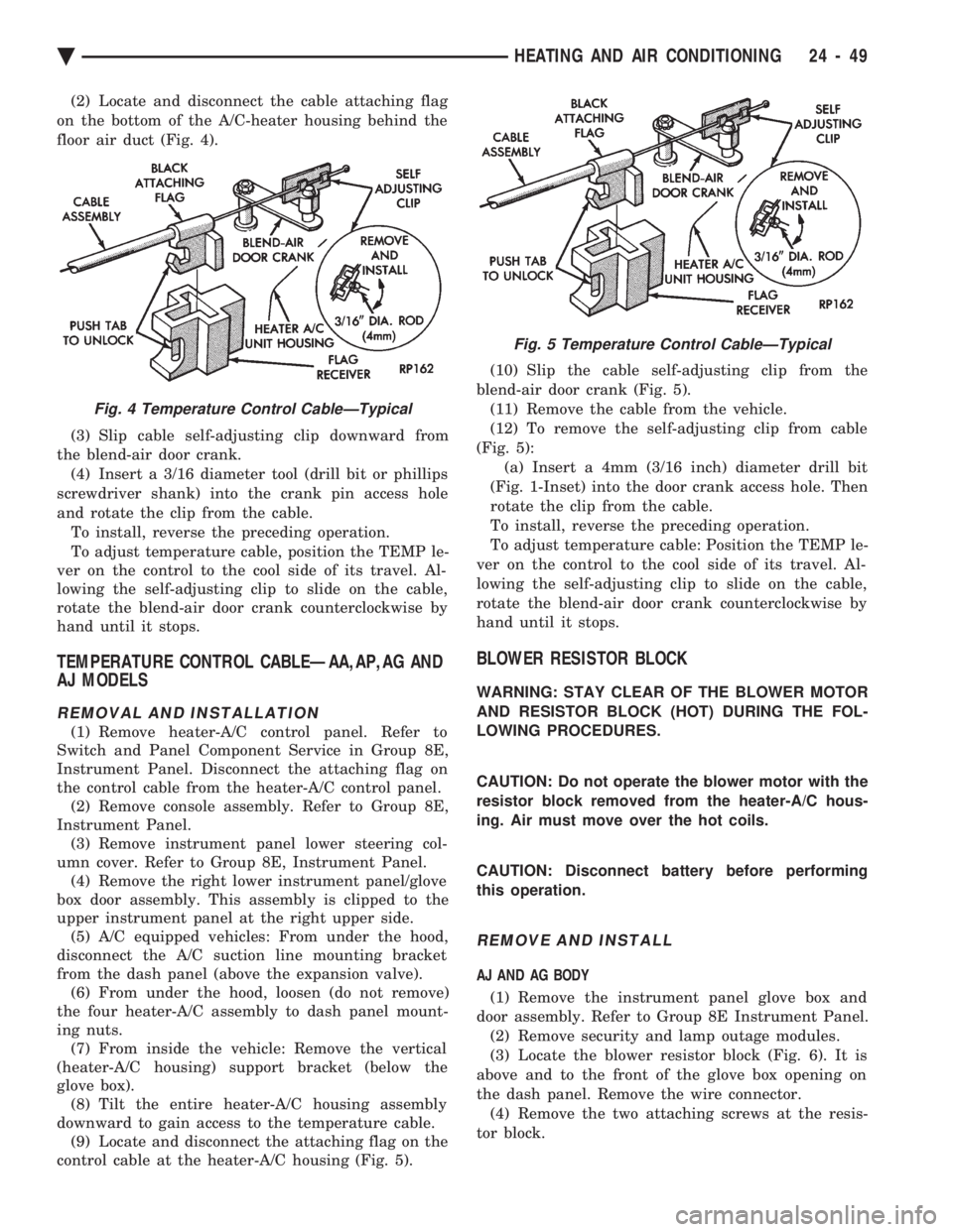
(2) Locate and disconnect the cable attaching flag
on the bottom of the A/C-heater housing behind the
floor air duct (Fig. 4).
(3) Slip cable self-adjusting clip downward from
the blend-air door crank. (4) Insert a 3/16 diameter tool (drill bit or phillips
screwdriver shank) into the crank pin access hole
and rotate the clip from the cable. To install, reverse the preceding operation.
To adjust temperature cable, position the TEMP le-
ver on the control to the cool side of its travel. Al-
lowing the self-adjusting clip to slide on the cable,
rotate the blend-air door crank counterclockwise by
hand until it stops.
TEMPERATURE CONTROL CABLEÐAA,AP,AG AND
AJ MODELS
REMOVAL AND INSTALLATION
(1) Remove heater-A/C control panel. Refer to
Switch and Panel Component Service in Group 8E,
Instrument Panel. Disconnect the attaching flag on
the control cable from the heater-A/C control panel. (2) Remove console assembly. Refer to Group 8E,
Instrument Panel. (3) Remove instrument panel lower steering col-
umn cover. Refer to Group 8E, Instrument Panel. (4) Remove the right lower instrument panel/glove
box door assembly. This assembly is clipped to the
upper instrument panel at the right upper side. (5) A/C equipped vehicles: From under the hood,
disconnect the A/C suction line mounting bracket
from the dash panel (above the expansion valve). (6) From under the hood, loosen (do not remove)
the four heater-A/C assembly to dash panel mount-
ing nuts. (7) From inside the vehicle: Remove the vertical
(heater-A/C housing) support bracket (below the
glove box). (8) Tilt the entire heater-A/C housing assembly
downward to gain access to the temperature cable. (9) Locate and disconnect the attaching flag on the
control cable at the heater-A/C housing (Fig. 5). (10) Slip the cable self-adjusting clip from the
blend-air door crank (Fig. 5). (11) Remove the cable from the vehicle.
(12) To remove the self-adjusting clip from cable
(Fig. 5): (a) Insert a 4mm (3/16 inch) diameter drill bit
(Fig. 1-Inset) into the door crank access hole. Then
rotate the clip from the cable.
To install, reverse the preceding operation.
To adjust temperature cable: Position the TEMP le-
ver on the control to the cool side of its travel. Al-
lowing the self-adjusting clip to slide on the cable,
rotate the blend-air door crank counterclockwise by
hand until it stops.
BLOWER RESISTOR BLOCK
WARNING: STAY CLEAR OF THE BLOWER MOTOR
AND RESISTOR BLOCK (HOT) DURING THE FOL-
LOWING PROCEDURES.
CAUTION: Do not operate the blower motor with the
resistor block removed from the heater-A/C hous-
ing. Air must move over the hot coils.
CAUTION: Disconnect battery before performing
this operation.
REMOVE AND INSTALL
AJ AND AG BODY
(1) Remove the instrument panel glove box and
door assembly. Refer to Group 8E Instrument Panel. (2) Remove security and lamp outage modules.
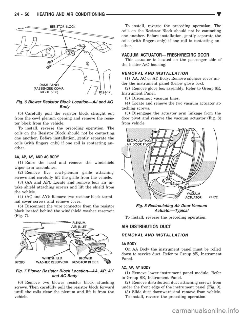
(3) Locate the blower resistor block (Fig. 6). It is
above and to the front of the glove box opening on
the dash panel. Remove the wire connector. (4) Remove the two attaching screws at the resis-
tor block.
Fig. 4 Temperature Control CableÐTypical
Fig. 5 Temperature Control CableÐTypical
Ä HEATING AND AIR CONDITIONING 24 - 49
Page 2354 of 2438
(5) Carefully pull the resistor block straight out
from the cowl plenum opening and remove the resis-
tor block from the vehicle. To install, reverse the preceding operation. The
coils on the Resistor Block should not be contacting
one another. Before installation, gently separate the
coils (with fingers only) if one coil is contacting an-
other.
AA, AP, AY, AND AC BODY
(1) Raise the hood and remove the windshield
wiper arm assemblies. (2) Remove five cowl-plenum grille attaching
screws and carefully lift the grille from the vehicle. (3) (AA and AP): Locate and remove four air in-
take shield attaching screws and lift the shield from
the vehicle. (4) (AC and AY): Remove two resistor block termi-
nal cover screws and remove cover. (5) Disconnect the wire connector from the resistor
block located behind the windshield washer reservoir
(Fig. 7).
(6) Remove two blower resistor block attaching
screws. Then carefully pull the resistor block forward
until the coils clear the plenum and lift it from the
vehicle. To install, reverse the preceding operation. The
coils on the Resistor Block should not be contacting
one another. Before installation, gently separate the
coils (with fingers only) if one coil is contacting an-
other.
VACUUM ACTUATORÐFRESH/RECIRC DOOR
This actuator is located on the passenger side of
the heater-A/C housing.
REMOVAL AND INSTALLATION
(1) AA, AC or AY Body: Remove silencer cover un-
der the instrument panel (below glove box). (2) Remove glove box assembly. Refer to Group 8E,
Instrument Panel. (3) Disconnect vacuum lines.
(4) Locate and remove the two vacuum actuator at-
taching screws. (5) Disengage the actuator arm linkage from the
door pivot and remove the vacuum actuator (Fig. 8)
from vehicle.
To install, reverse the preceding operation.
AIR DISTRIBUTION DUCT
REMOVAL AND INSTALLATION
AA BODY On AA Body the instrument panel must be rolled
down to service duct. Refer to Group 8E, Instrument
Panel.
AC, AP, AY BODY (1) Remove lower instrument panel module. Refer
to Group 8E, Instrument Panel. (2) Remove distribution duct attaching screws from
under the front edge of the instrument panel (Fig. 9). (3) Slide duct downward and remove from vehicle.
To install, reverse the preceding operation.
Fig. 6 Blower Resistor Block LocationÐAJ and AG Body
Fig. 7 Blower Resistor Block LocationÐAA, AP, AYand AC Body
Fig. 8 Recirculating Air Door VacuumActuatorÐTypical
24 - 50 HEATING AND AIR CONDITIONING Ä
Page 2356 of 2438
To install, reverse the preceding operation.
VACUUM ACTUATORSÐMODE DOORS
The Vacuum Actuators for the Mode Doors are lo-
cated on the drivers side of heater/AC housing above
the accelerator pedal.
REMOVAL
(1) Remove the instrument panel cover under the
steering column. Refer to Group 8E, Instrument
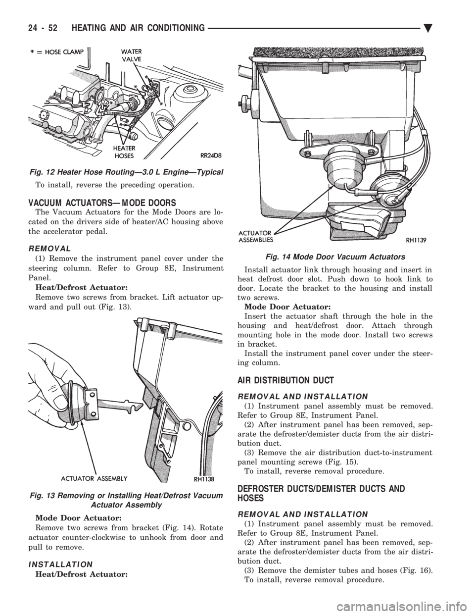
Panel. Heat/Defrost Actuator:
Remove two screws from bracket. Lift actuator up-
ward and pull out (Fig. 13).
Mode Door Actuator:
Remove two screws from bracket (Fig. 14). Rotate
actuator counter-clockwise to unhook from door and
pull to remove.
INSTALLATION
Heat/Defrost Actuator: Install actuator link through housing and insert in
heat defrost door slot. Push down to hook link to
door. Locate the bracket to the housing and install
two screws. Mode Door Actuator:
Insert the actuator shaft through the hole in the
housing and heat/defrost door. Attach through
mounting hole in the mode door. Install two screws
in bracket. Install the instrument panel cover under the steer-
ing column.
AIR DISTRIBUTION DUCT
REMOVAL AND INSTALLATION
(1) Instrument panel assembly must be removed.
Refer to Group 8E, Instrument Panel. (2) After instrument panel has been removed, sep-
arate the defroster/demister ducts from the air distri-
bution duct. (3) Remove the air distribution duct-to-instrument
panel mounting screws (Fig. 15). To install, reverse removal procedure.
DEFROSTER DUCTS/DEMISTER DUCTS AND
HOSES
REMOVAL AND INSTALLATION
(1) Instrument panel assembly must be removed.
Refer to Group 8E, Instrument Panel. (2) After instrument panel has been removed, sep-
arate the defroster/demister ducts from the air distri-
bution duct. (3) Remove the demister tubes and hoses (Fig. 16).
To install, reverse removal procedure.
Fig. 12 Heater Hose RoutingÐ3.0 L EngineÐTypical
Fig. 13 Removing or Installing Heat/Defrost Vacuum Actuator Assembly
Fig. 14 Mode Door Vacuum Actuators
24 - 52 HEATING AND AIR CONDITIONING Ä
Page 2362 of 2438
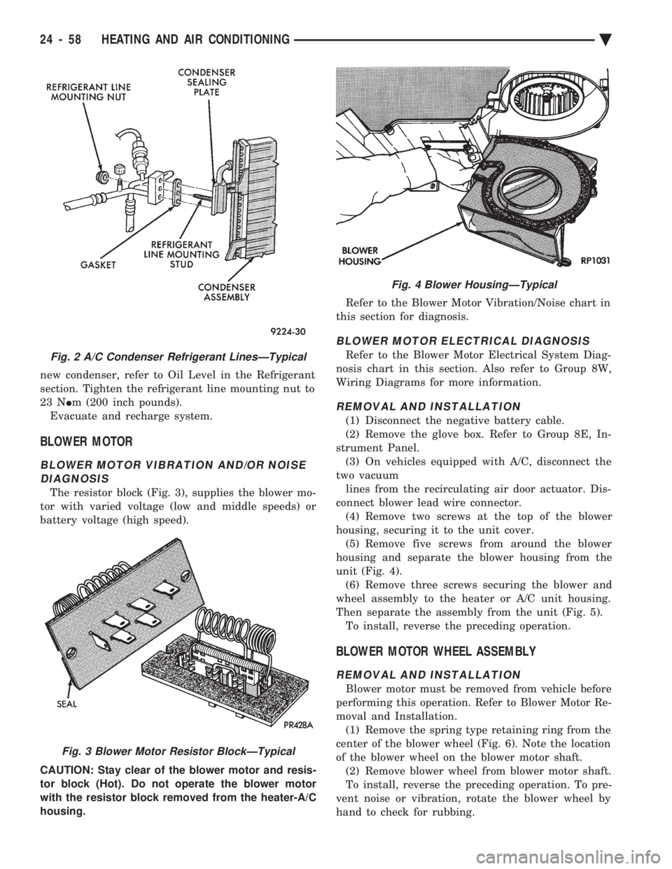
new condenser, refer to Oil Level in the Refrigerant
section. Tighten the refrigerant line mounting nut to
23 N Im (200 inch pounds).
Evacuate and recharge system.
BLOWER MOTOR
BLOWER MOTOR VIBRATION AND/OR NOISE DIAGNOSIS
The resistor block (Fig. 3), supplies the blower mo-
tor with varied voltage (low and middle speeds) or
battery voltage (high speed).
CAUTION: Stay clear of the blower motor and resis-
tor block (Hot). Do not operate the blower motor
with the resistor block removed from the heater-A/C
housing. Refer to the Blower Motor Vibration/Noise chart in
this section for diagnosis.
BLOWER MOTOR ELECTRICAL DIAGNOSIS
Refer to the Blower Motor Electrical System Diag-
nosis chart in this section. Also refer to Group 8W,
Wiring Diagrams for more information.
REMOVAL AND INSTALLATION
(1) Disconnect the negative battery cable.
(2) Remove the glove box. Refer to Group 8E, In-
strument Panel. (3) On vehicles equipped with A/C, disconnect the
two vacuum lines from the recirculating air door actuator. Dis-
connect blower lead wire connector. (4) Remove two screws at the top of the blower
housing, securing it to the unit cover. (5) Remove five screws from around the blower
housing and separate the blower housing from the
unit (Fig. 4). (6) Remove three screws securing the blower and
wheel assembly to the heater or A/C unit housing.
Then separate the assembly from the unit (Fig. 5). To install, reverse the preceding operation.
BLOWER MOTOR WHEEL ASSEMBLY
REMOVAL AND INSTALLATION
Blower motor must be removed from vehicle before
performing this operation. Refer to Blower Motor Re-
moval and Installation. (1) Remove the spring type retaining ring from the
center of the blower wheel (Fig. 6). Note the location
of the blower wheel on the blower motor shaft. (2) Remove blower wheel from blower motor shaft.
To install, reverse the preceding operation. To pre-
vent noise or vibration, rotate the blower wheel by
hand to check for rubbing.
Fig. 2 A/C Condenser Refrigerant LinesÐTypical
Fig. 3 Blower Motor Resistor BlockÐTypical
Fig. 4 Blower HousingÐTypical
24 - 58 HEATING AND AIR CONDITIONING Ä
Page 2368 of 2438
(3) To remove the top cover from the A/C-heater
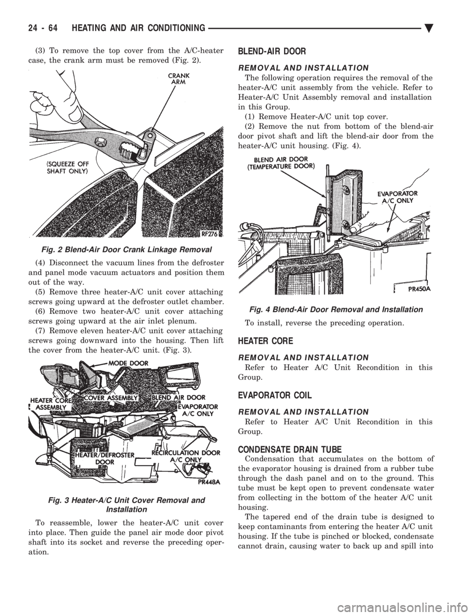
case, the crank arm must be removed (Fig. 2).
(4) Disconnect the vacuum lines from the defroster
and panel mode vacuum actuators and position them
out of the way. (5) Remove three heater-A/C unit cover attaching
screws going upward at the defroster outlet chamber. (6) Remove two heater-A/C unit cover attaching
screws going upward at the air inlet plenum. (7) Remove eleven heater-A/C unit cover attaching
screws going downward into the housing. Then lift
the cover from the heater-A/C unit. (Fig. 3).
To reassemble, lower the heater-A/C unit cover
into place. Then guide the panel air mode door pivot
shaft into its socket and reverse the preceding oper-
ation.BLEND-AIR DOOR
REMOVAL AND INSTALLATION
The following operation requires the removal of the
heater-A/C unit assembly from the vehicle. Refer to
Heater-A/C Unit Assembly removal and installation
in this Group. (1) Remove Heater-A/C unit top cover.
(2) Remove the nut from bottom of the blend-air
door pivot shaft and lift the blend-air door from the
heater-A/C unit housing. (Fig. 4).
To install, reverse the preceding operation.
HEATER CORE
REMOVAL AND INSTALLATION
Refer to Heater A/C Unit Recondition in this
Group.
EVAPORATOR COIL
REMOVAL AND INSTALLATION
Refer to Heater A/C Unit Recondition in this
Group.
CONDENSATE DRAIN TUBE
Condensation that accumulates on the bottom of
the evaporator housing is drained from a rubber tube
through the dash panel and on to the ground. This
tube must be kept open to prevent condensate water
from collecting in the bottom of the heater A/C unit
housing. The tapered end of the drain tube is designed to
keep contaminants from entering the heater A/C unit
housing. If the tube is pinched or blocked, condensate
cannot drain, causing water to back up and spill into
Fig. 2 Blend-Air Door Crank Linkage Removal
Fig. 3 Heater-A/C Unit Cover Removal and Installation
Fig. 4 Blend-Air Door Removal and Installation
24 - 64 HEATING AND AIR CONDITIONING Ä
Page 2370 of 2438
AUTOMATIC TEMPERATURE CONTROL (ATC) INDEX
page page
Ambient Temperature Sensor ............... 67
ATC Computer/Control Panel ................ 66
Blend-Air Door Actuator .................... 69
Computer Aided Diagnostic Tests ............ 72
Diagnostic Trouble Code Definitions .......... 73
Diagnostic Trouble Code Service Procedures . . . 74
Erasing Diagnostic Trouble Codes ............ 83
Fresh/Recirc Door Actuator ................. 68 General InformationÐComponent Operation
.... 66
In-Car Temperature Sensor/Aspirator Assembly . . 70
Manual A/C Mode ........................ 66
Mode Door Actuator ...................... 69
NonÐComputer Aided Diagnostic Tests ....... 72
Power Module ........................... 67
Sun Sensor ............................. 71
Water Temperature Sensor ................. 71
GENERAL INFORMATIONÐCOMPONENT
OPERATION
The Automatic Temperature Control (ATC) system
lets the operator change the passenger compartment
environment. A computer, built into the control
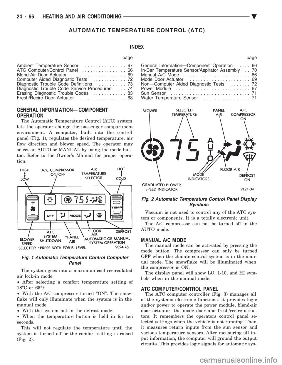
panel (Fig. 1), regulates the desired temperature, air
flow direction and blower speed. The operator may
select an AUTO or MANUAL by using the mode but-
ton. Refer to the Owner's Manual for proper opera-
tion.
The system goes into a maximum cool recirculated
air lock-in mode:
² After selecting a comfort temperature setting of
18ÉC or 65ÉF.
² With the A/C compressor turned ``ON''. The snow-
flake will only illuminate when the system is in the
manual mode.
² With the system not in the defrost mode.
² When the temperature button is held in for ten
seconds. This will not regulate the temperature until the
system is turned off or the comfort setting is raised
(Fig. 2). Vacuum is not used to control any of the ATC sys-
tem or components. It is a totally electronic unit. The A/C compressor can not be turned off in the
AUTO mode.
MANUAL A/C MODE
The manual mode can be activated by pressing the
mode button. The compressor can only be turned
OFF when the climate control system is in the man-
ual mode. The snowflake will be illuminated when
the compressor is ON. The display panel will show LO, 1-10, and HI sym-
bols when in the manual mode.
ATC COMPUTER/CONTROL PANEL
The ATC computer controller (Fig. 3) manages all
of the systems electronic functions. It provides logic
and/or power to operate the power module, blend-air
door actuator, the mode door and fresh/recirc actua-
tors. It remembers the operators control panel se-
lected settings when the vehicle is not running. Then
it measures return inputs from the sun sensor and
various temperature sensors. After measuring all in-
put information, the computer will ground the output
circuits. This provides logic signals for automatic sys-
Fig. 1 Automatic Temperature Control Computer Panel
Fig. 2 Automatic Temperature Control Panel Display Symbols
24 - 66 HEATING AND AIR CONDITIONING Ä
Page 2373 of 2438
To install, reverse the preceding operation.
BLEND-AIR DOOR ACTUATOR
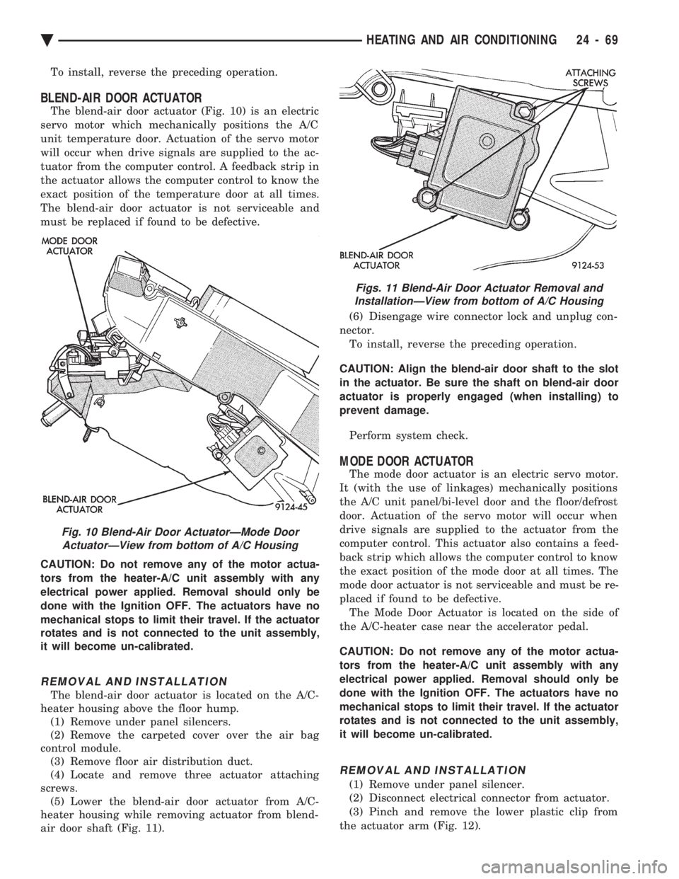
The blend-air door actuator (Fig. 10) is an electric
servo motor which mechanically positions the A/C
unit temperature door. Actuation of the servo motor
will occur when drive signals are supplied to the ac-
tuator from the computer control. A feedback strip in
the actuator allows the computer control to know the
exact position of the temperature door at all times.
The blend-air door actuator is not serviceable and
must be replaced if found to be defective.
CAUTION: Do not remove any of the motor actua-
tors from the heater-A/C unit assembly with any
electrical power applied. Removal should only be
done with the Ignition OFF. The actuators have no
mechanical stops to limit their travel. If the actuator
rotates and is not connected to the unit assembly,
it will become un-calibrated.
REMOVAL AND INSTALLATION
The blend-air door actuator is located on the A/C-
heater housing above the floor hump. (1) Remove under panel silencers.
(2) Remove the carpeted cover over the air bag
control module. (3) Remove floor air distribution duct.
(4) Locate and remove three actuator attaching
screws. (5) Lower the blend-air door actuator from A/C-
heater housing while removing actuator from blend-
air door shaft (Fig. 11). (6) Disengage wire connector lock and unplug con-
nector. To install, reverse the preceding operation.
CAUTION: Align the blend-air door shaft to the slot
in the actuator. Be sure the shaft on blend-air door
actuator is properly engaged (when installing) to
prevent damage.
Perform system check.
MODE DOOR ACTUATOR
The mode door actuator is an electric servo motor.
It (with the use of linkages) mechanically positions
the A/C unit panel/bi-level door and the floor/defrost
door. Actuation of the servo motor will occur when
drive signals are supplied to the actuator from the
computer control. This actuator also contains a feed-
back strip which allows the computer control to know
the exact position of the mode door at all times. The
mode door actuator is not serviceable and must be re-
placed if found to be defective. The Mode Door Actuator is located on the side of
the A/C-heater case near the accelerator pedal.
CAUTION: Do not remove any of the motor actua-
tors from the heater-A/C unit assembly with any
electrical power applied. Removal should only be
done with the Ignition OFF. The actuators have no
mechanical stops to limit their travel. If the actuator
rotates and is not connected to the unit assembly,
it will become un-calibrated.
REMOVAL AND INSTALLATION
(1) Remove under panel silencer.
(2) Disconnect electrical connector from actuator.
(3) Pinch and remove the lower plastic clip from
the actuator arm (Fig. 12).
Fig. 10 Blend-Air Door ActuatorÐMode Door ActuatorÐView from bottom of A/C Housing
Figs. 11 Blend-Air Door Actuator Removal andInstallationÐView from bottom of A/C Housing
Ä HEATING AND AIR CONDITIONING 24 - 69
Page 2375 of 2438
(3) Remove the two aspirator mounting screws.
(4) Disconnect the aspirator intake hose from the
instrument panel. (5) Remove sensor/aspirator and it's wiring har-
ness from vehicle. To install, reverse the preceding operation.
WATER TEMPERATURE SENSOR
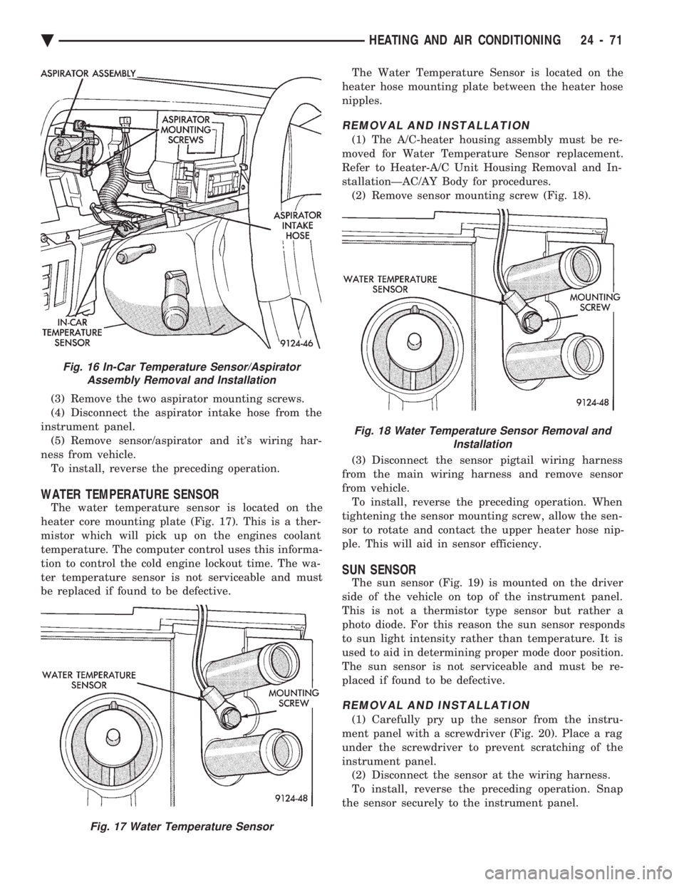
The water temperature sensor is located on the
heater core mounting plate (Fig. 17). This is a ther-
mistor which will pick up on the engines coolant
temperature. The computer control uses this informa-
tion to control the cold engine lockout time. The wa-
ter temperature sensor is not serviceable and must
be replaced if found to be defective. The Water Temperature Sensor is located on the
heater hose mounting plate between the heater hose
nipples.
REMOVAL AND INSTALLATION
(1) The A/C-heater housing assembly must be re-
moved for Water Temperature Sensor replacement.
Refer to Heater-A/C Unit Housing Removal and In-
stallationÐAC/AY Body for procedures. (2) Remove sensor mounting screw (Fig. 18).
(3) Disconnect the sensor pigtail wiring harness
from the main wiring harness and remove sensor
from vehicle. To install, reverse the preceding operation. When
tightening the sensor mounting screw, allow the sen-
sor to rotate and contact the upper heater hose nip-
ple. This will aid in sensor efficiency.
SUN SENSOR
The sun sensor (Fig. 19) is mounted on the driver
side of the vehicle on top of the instrument panel.
This is not a thermistor type sensor but rather a
photo diode. For this reason the sun sensor responds
to sun light intensity rather than temperature. It is
used to aid in determining proper mode door position.
The sun sensor is not serviceable and must be re-
placed if found to be defective.
REMOVAL AND INSTALLATION
(1) Carefully pry up the sensor from the instru-
ment panel with a screwdriver (Fig. 20). Place a rag
under the screwdriver to prevent scratching of the
instrument panel. (2) Disconnect the sensor at the wiring harness.
To install, reverse the preceding operation. Snap
the sensor securely to the instrument panel.
Fig. 16 In-Car Temperature Sensor/Aspirator Assembly Removal and Installation
Fig. 17 Water Temperature Sensor
Fig. 18 Water Temperature Sensor Removal and Installation
Ä HEATING AND AIR CONDITIONING 24 - 71