1993 CHEVROLET PLYMOUTH ACCLAIM door lock
[x] Cancel search: door lockPage 1469 of 2438
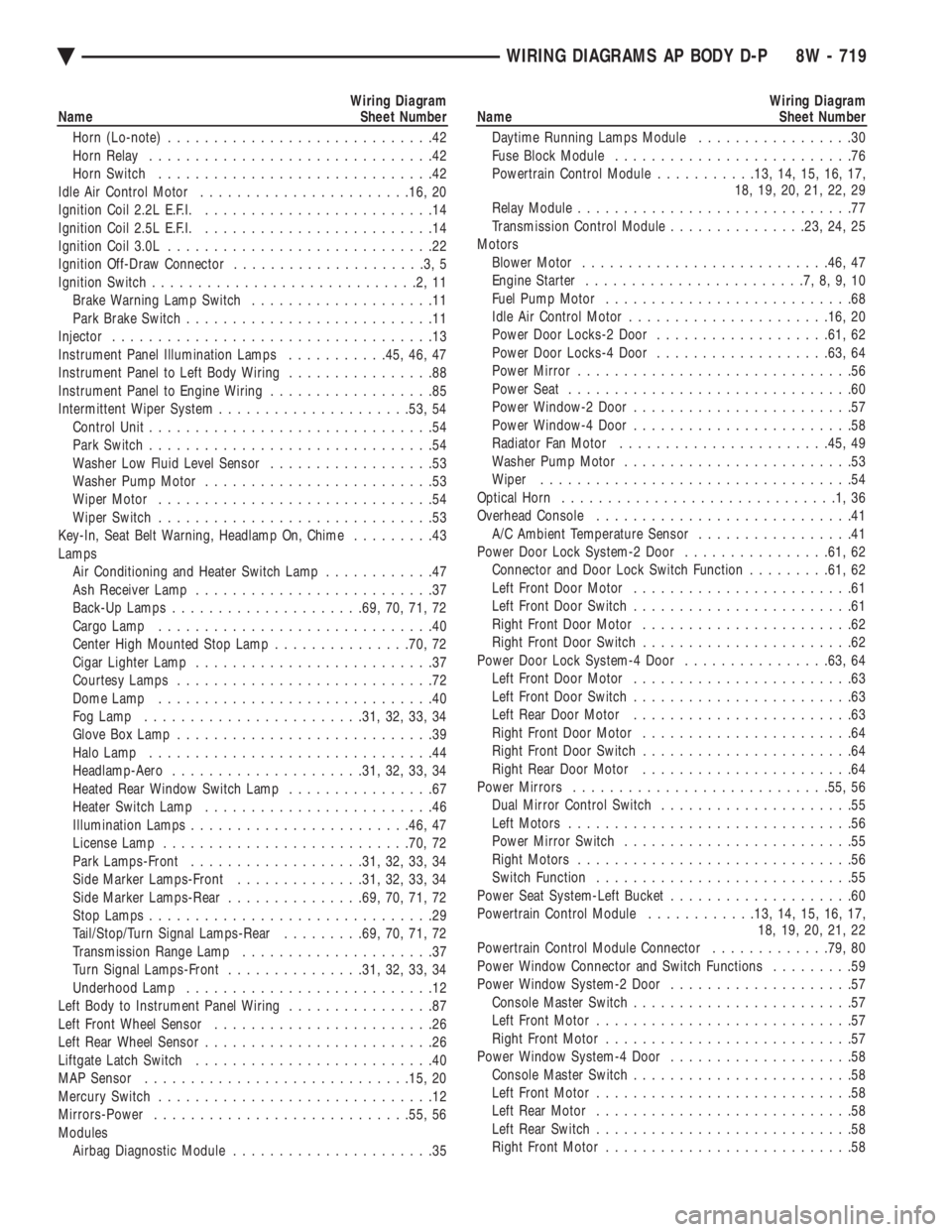
Wiring Diagram
Name Sheet Number
Horn (Lo-note) .............................42
Horn Relay ...............................42
Horn Switch ..............................42
Idle Air Control Motor ...................... .16, 20
Ignition Coil 2.2L E.F.I. .........................14
Ignition Coil 2.5L E.F.I. .........................14
Ignition Coil 3.0L .............................22
Ignition Off-Draw Connector .....................3,5
Ignition Switch .............................2,11
Brake Warning Lamp Switch ....................11
Park Brake Switch ...........................11
Injector ...................................13
Instrument Panel Illumination Lamps ...........45, 46, 47
Instrument Panel to Left Body Wiring ................88
Instrument Panel to Engine Wiring ..................85
Intermittent Wiper System .................... .53, 54
Control Unit ...............................54
Park Switch ...............................54
Washer Low Fluid Level Sensor ..................53
Washer Pump Motor .........................53
Wiper Motor ..............................54
Wiper Switch ..............................53
Key-In, Seat Belt Warning, Headlamp On, Chime .........43
Lamps Air Conditioning and Heater Switch Lamp ............47
Ash Receiver Lamp ..........................37
Back-Up Lamps .................... .69, 70, 71, 72
Cargo Lamp ..............................40
Center High Mounted Stop Lamp ...............70, 72
Cigar Lighter Lamp ..........................37
Courtesy Lamps ............................72
Dome Lamp ..............................40
Fog Lamp ....................... .31, 32, 33, 34
Glove Box Lamp ............................39
Halo Lamp ...............................44
Headlamp-Aero .................... .31, 32, 33, 34
Heated Rear Window Switch Lamp ................67
Heater Switch Lamp .........................46
Illumination Lamps ....................... .46, 47
License Lamp .......................... .70, 72
Park Lamps-Front .................. .31, 32, 33, 34
Side Marker Lamps-Front ..............31, 32, 33, 34
Side Marker Lamps-Rear ...............69, 70, 71, 72
Stop Lamps ...............................29
Tail/Stop/Turn Signal Lamps-Rear .........69, 70, 71, 72
Transmission Range Lamp .....................37
Turn Signal Lamps-Front ...............31, 32, 33, 34
Underhood Lamp ...........................12
Left Body to Instrument Panel Wiring ................87
Left Front Wheel Sensor ........................26
Left Rear Wheel Sensor .........................26
Liftgate Latch Switch ..........................40
MAP Sensor ............................ .15, 20
Mercury Switch ..............................12
Mirrors-Power ........................... .55, 56
Modules Airbag Diagnostic Module ......................35Wiring Diagram
Name Sheet Number
Daytime Running Lamps Module .................30
Fuse Block Module ..........................76
Powertrain Control Module ...........13, 14, 15, 16, 17,
18, 19, 20, 21, 22, 29
Relay Module ..............................77
Transmission Control Module ...............23, 24, 25
Motors Blower Motor .......................... .46, 47
Engine Starter ........................7,8,9,10
Fuel Pump Motor ...........................68
Idle Air Control Motor ..................... .16, 20
Power Door Locks-2 Door .................. .61, 62
Power Door Locks-4 Door .................. .63, 64
Power Mirror ..............................56
Power Seat ...............................60
Power Window-2 Door ........................57
Power Window-4 Door ........................58
Radiator Fan Motor ...................... .45, 49
Washer Pump Motor .........................53
Wiper ..................................54
Optical Horn ..............................1,36
Overhead Console ............................41
A/C Ambient Temperature Sensor .................41
Power Door Lock System-2 Door ................61, 62
Connector and Door Lock Switch Function .........61, 62
Left Front Door Motor ........................61
Left Front Door Switch ........................61
Right Front Door Motor .......................62
Right Front Door Switch .......................62
Power Door Lock System-4 Door ................63, 64
Left Front Door Motor ........................63
Left Front Door Switch ........................63
Left Rear Door Motor ........................63
Right Front Door Motor .......................64
Right Front Door Switch .......................64
Right Rear Door Motor .......................64
Power Mirrors ........................... .55, 56
Dual Mirror Control Switch .....................55
Left Motors ...............................56
Power Mirror Switch .........................55
Right Motors ..............................56
Switch Function ............................55
Power Seat System-Left Bucket ....................60
Powertrain Control Module ............13, 14, 15, 16, 17,
18, 19, 20, 21, 22
Powertrain Control Module Connector .............79, 80
Power Window Connector and Switch Functions .........59
Power Window System-2 Door ....................57
Console Master Switch ........................57
Left Front Motor ............................57
Right Front Motor ...........................57
Power Window System-4 Door ....................58
Console Master Switch ........................58
Left Front Motor ............................58
Left Rear Motor ............................58
Left Rear Switch ............................58
Right Front Motor ...........................58
Ä WIRING DIAGRAMS AP BODY D-P 8W - 719
Page 1471 of 2438
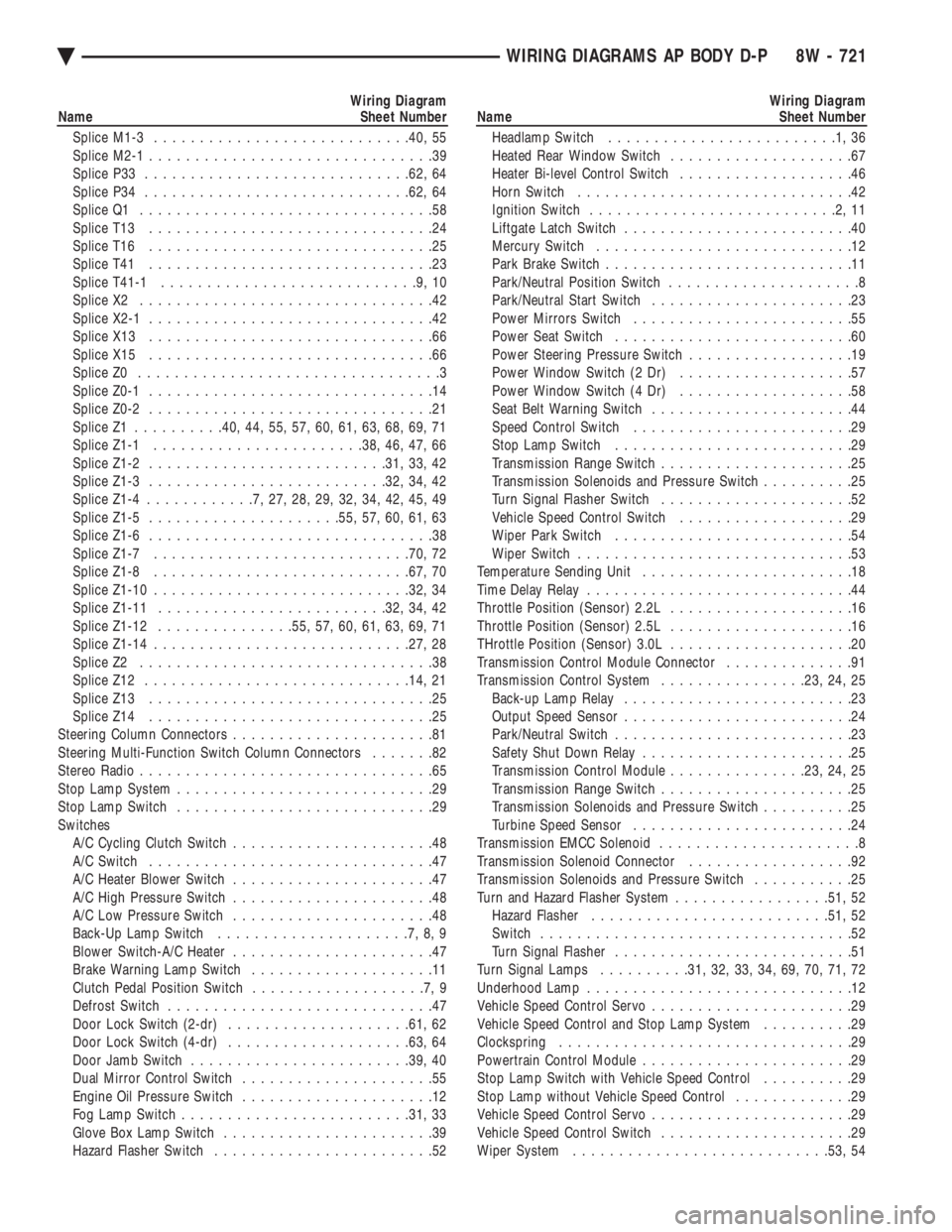
Wiring Diagram
Name Sheet Number
Splice M1-3 ........................... .40, 55
Splice M2-1 ...............................39
Splice P33 ............................ .62, 64
Splice P34 ............................ .62, 64
Splice Q1 ................................58
Splice T13 ...............................24
Splice T16 ...............................25
Splice T41 ...............................23
Splice T41-1 ............................9,10
Splice X2 ................................42
Splice X2-1 ...............................42
Splice X13 ...............................66
Splice X15 ...............................66
Splice Z0 .................................3
Splice Z0-1 ...............................14
Splice Z0-2 ...............................21
Splice Z1 ......... .40, 44, 55, 57, 60, 61, 63, 68, 69, 71
Splice Z1-1 ...................... .38, 46, 47, 66
Splice Z1-2 ......................... .31, 33, 42
Splice Z1-3 ......................... .32, 34, 42
Splice Z1-4 ............7,27,28,29,32,34,42,45,49
Splice Z1-5 .................... .55, 57, 60, 61, 63
Splice Z1-6 ...............................38
Splice Z1-7 ........................... .70, 72
Splice Z1-8 ........................... .67, 70
Splice Z1-10 ........................... .32, 34
Splice Z1-11 ........................ .32, 34, 42
Splice Z1-12 .............. .55, 57, 60, 61, 63, 69, 71
Splice Z1-14 ........................... .27, 28
Splice Z2 ................................38
Splice Z12 ............................ .14, 21
Splice Z13 ...............................25
Splice Z14 ...............................25
Steering Column Connectors ......................81
Steering Multi-Function Switch Column Connectors .......82
Stereo Radio ................................65
Stop Lamp System ............................29
Stop Lamp Switch ............................29
Switches A/C Cycling Clutch Switch ......................48
A/C Switch ...............................47
A/C Heater Blower Switch ......................47
A/C High Pressure Switch ......................48
A/C Low Pressure Switch ......................48
Back-Up Lamp Switch .....................7,8,9
Blower Switch-A/C Heater ......................47
Brake Warning Lamp Switch ....................11
Clutch Pedal Position Switch ...................7,9
Defrost Switch .............................47
Door Lock Switch (2-dr) ................... .61, 62
Door Lock Switch (4-dr) ................... .63, 64
Door Jamb Switch ....................... .39, 40
Dual Mirror Control Switch .....................55
Engine Oil Pressure Switch .....................12
Fog Lamp Switch ........................ .31, 33
Glove Box Lamp Switch .......................39
Hazard Flasher Switch ........................52Wiring Diagram
Name Sheet Number
Headlamp Switch .........................1,36
Heated Rear Window Switch ....................67
Heater Bi-level Control Switch ...................46
Horn Switch ..............................42
Ignition Switch ...........................2,11
Liftgate Latch Switch .........................40
Mercury Switch ............................12
Park Brake Switch ...........................11
Park/Neutral Position Switch .....................8
Park/Neutral Start Switch ......................23
Power Mirrors Switch ........................55
Power Seat Switch ..........................60
Power Steering Pressure Switch ..................19
Power Window Switch (2 Dr) ...................57
Power Window Switch (4 Dr) ...................58
Seat Belt Warning Switch ......................44
Speed Control Switch ........................29
Stop Lamp Switch ..........................29
Transmission Range Switch .....................25
Transmission Solenoids and Pressure Switch ..........25
Turn Signal Flasher Switch .....................52
Vehicle Speed Control Switch ...................29
Wiper Park Switch ..........................54
Wiper Switch ..............................53
Temperature Sending Unit .......................18
Time Delay Relay .............................44
Throttle Position (Sensor) 2.2L ....................16
Throttle Position (Sensor) 2.5L ....................16
THrottle Position (Sensor) 3.0L ....................20
Transmission Control Module Connector ..............91
Transmission Control System ................23, 24, 25
Back-up Lamp Relay .........................23
Output Speed Sensor .........................24
Park/Neutral Switch ..........................23
Safety Shut Down Relay .......................25
Transmission Control Module ...............23, 24, 25
Transmission Range Switch .....................25
Transmission Solenoids and Pressure Switch ..........25
Turbine Speed Sensor ........................24
Transmission EMCC Solenoid ......................8
Transmission Solenoid Connector ..................92
Transmission Solenoids and Pressure Switch ...........25
Turn and Hazard Flasher System .................51, 52
Hazard Flasher ......................... .51, 52
Switch ..................................52
Turn Signal Flasher ..........................51
Turn Signal Lamps ..........31, 32, 33, 34, 69, 70, 71, 72
Underhood Lamp .............................12
Vehicle Speed Control Servo ......................29
Vehicle Speed Control and Stop Lamp System ..........29
Clockspring ................................29
Powertrain Control Module .......................29
Stop Lamp Switch with Vehicle Speed Control ..........29
Stop Lamp without Vehicle Speed Control .............29
Vehicle Speed Control Servo ......................29
Vehicle Speed Control Switch .....................29
Wiper System ........................... .53, 54
Ä WIRING DIAGRAMS AP BODY D-P 8W - 721
Page 2158 of 2438
BODY DIAGNOSTIC PROCEDURES INDEX
page page
Water Leaks ............................. 2 Wind Noise.............................. 3
WATER LEAKS
Water leaks can be caused by poor sealing, improper
body component alignment, body seam porosity, miss-
ing plugs, or blocked drain holes. Centrifugal and
gravitational force can cause water to drip from an
area somewhat distant from the actual leak point,
making leak detection difficult. All body sealing points
should be water tight in normal wet driving conditions.
Water flowing downward from the front of the vehicle
should not enter the passenger or luggage compart-
ment. Moving sealing surfaces will not always seal
water tight under all conditions. At times, side glass,
door, or convertible top seals will allow water to enter
the passenger compartment during high pressure
washing or hard driving rain (severe) conditions. Over
compensating on door, glass, or top adjustments to stop
a water leak that occurs under severe conditions, can
cause premature seal wear and excessive closing or
latching effort. After a repair procedure has been
performed, water test vehicle to verify leak has stopped
before returning vehicle to use.
VISUAL INSPECTION BEFORE WATER LEAK TESTS
Verify that floor and body plugs are in place, body
drains are clear and body components are aligned and
sealed. If component alignment or sealing is necessary,
refer to the appropriate section of this group for proper
procedures.
WATER LEAK TESTS
WARNING: DO NOT USE ELECTRIC SHOP LIGHTS
OR TOOLS IN WATER TEST AREA, PERSONAL IN-
JURY CAN RESULT.
When a determination has been made on the condi-
tions that a water leak occurs, simulate the conditions
as closely as possible.
² If a leak occurs when the car is parked in a steady
light rain, flood the leak area with a open ended garden
hose.
² If a leak occurs at highway speeds in a steady rain,
test the leak area with a stream or fan spray of water
from a garden hose with an adjustable nozzle. Direct
the spray in the direction comparable to actual condi-
tions. ²
If a leak seems to occur only when the vehicle is
parked on an incline, hoist the end or side of the vehicle
to simulate this condition before water testing. This
method can also be used when the leak occurs when the
vehicle accelerates, stops, or turns. If the leak occurs
on acceleration, hoist the front of the vehicle. If the
leak occurs when braking, hoist the back of the vehicle.
If the leak occurs on left turns, hoist the left side of the
vehicle. If the leak occurs on right turns, hoist the right
side of the vehicle. For hoisting recommendations refer
to Group 0, Lubrication and Maintenance, General
Information section.
WATER LEAK DETECTION
To detect a water leak point of entry, perform a water
test and watch for water tracks or droplets forming on
the inside if the vehicle. If necessary remove interior
trim covers or panels to gain visual access to the leak
area. If the hose can not be positioned without being
held, have someone help perform the water test. Some water leaks must be tested for a considerable
length of time to become apparent. When a leak ap-
pears, determine the highest point of the water track or
drop. The highest point usually will indicate the point
of entry. After leak point has been determined, repair
the leak and water test to verify that leak has stopped. Locating the entry point of water that is leaking into
a cavity between panels can be difficult. The trapped
water splashes or runs from the cavity it is dammed up
in, often at a distance from the entry point. Most water
leaks of this type become apparent after accelerating,
stopping, turning, or when on a incline.
MIRROR INSPECTION METHOD
When a leak point area is visually obstructed, use a
suitable mirror to gain visual access. A mirror can also
be used to deflect light to a limited access area to assist
in locating a leak point.
BRIGHT LIGHT LEAK TEST METHOD
Some water leaks in the luggage compartment can be
detected without water testing. Position the vehicle in
a brightly light area. From inside the darkened lug-
gage compartment inspect around seals and body
seams. If necessary, have a helper direct a drop light
over the suspected leak areas around the lug-
23 - 2 BODY Ä
Page 2167 of 2438
AA-VEHICLE BODY COMPONENT SERVICE INDEX
page page
A-Pillar and Roof Rail Mouldings ............. 25
B-Pillar Trim Panel ....................... 25
Body Side Moulding and Applique ............ 24
Cowl Cover ............................. 13
Cowl Panel Trim and Scuff Plates ............ 25
Door Opening Weatherstrips ................ 24
Floor Carpet ............................ 30
Front Center Console ..................... 29
Front Door and Hinge ..................... 15
Front Door Belt Moulding and Weatherstrip ..... 17
Front Door Glass ........................ 17
Front Door Glass Channel and Run Weatherstrip . 18
Front Door Glass Run Lower Channel ......... 18
Front Door Latch ......................... 16
Front Door Side View Mirror ................ 17
Front Door Silencer and Water Shield ......... 15
Front Door Trim Panel .................... 14
Front Door Window Regulator/Manual ......... 18
Front Door Window Regulator/Power .......... 19
Front End Splash Shields .................. 13
Front Fender ............................ 14
Front Power Door Lock Actuator ............. 19
Front Seat Belts ......................... 27
Front Seats ............................. 28
Fuel Fill Door ........................... 36
Grille .................................. 11
Head Lining ............................. 30
Hood and Hinges ........................ 11
Hood Latch and Release Cable .............. 12
Outside Front Door Latch Release Handle ..... 16
Outside Rear Door Latch Release Handle ...... 21 Overhead Console
........................ 30
Quarter Extension Trim Panel ............... 27
Quarter Trim Panel ....................... 27
Rear Deck Filler Panel .................... 31
Rear Door and Hinge ..................... 20
Rear Door Belt Moulding and Weatherstrip ..... 22
Rear Door Glass ......................... 22
Rear Door Glass Run Weatherstrip ........... 22
Rear Door Glass Stationary Glass Module ..... 23
Rear Door Latch ......................... 21
Rear Door Silencer and Water Shield ......... 20
Rear Door Trim Panel ..................... 20
Rear Door Window Regulator/Manual ......... 23
Rear Door Window Regulator/Power .......... 23
Rear Power Door Lock Actuator ............. 22
Rear Seat Belts .......................... 28
Rear Seats ............................. 28
Rear Shelf Trim Panel ..................... 27
Rear Window Glass ...................... 32
Sun Roof Air Deflector .................... 31
Sun Roof Drain Tubes .................... 31
Sun Roof Weatherstrip .................... 31
Trunk Lid .............................. 33
Trunk Lid Hinge ......................... 34
Trunk Lid Latch .......................... 34
Trunk Lid Lock .......................... 34
Trunk Lid Luggage Rack ................... 35
Trunk Lid Torsion Bar ..................... 34
Trunk Lining ............................ 35
Trunk Opening Weatherstrip ................ 35
Vinyl Roof Bonnet ........................ 31
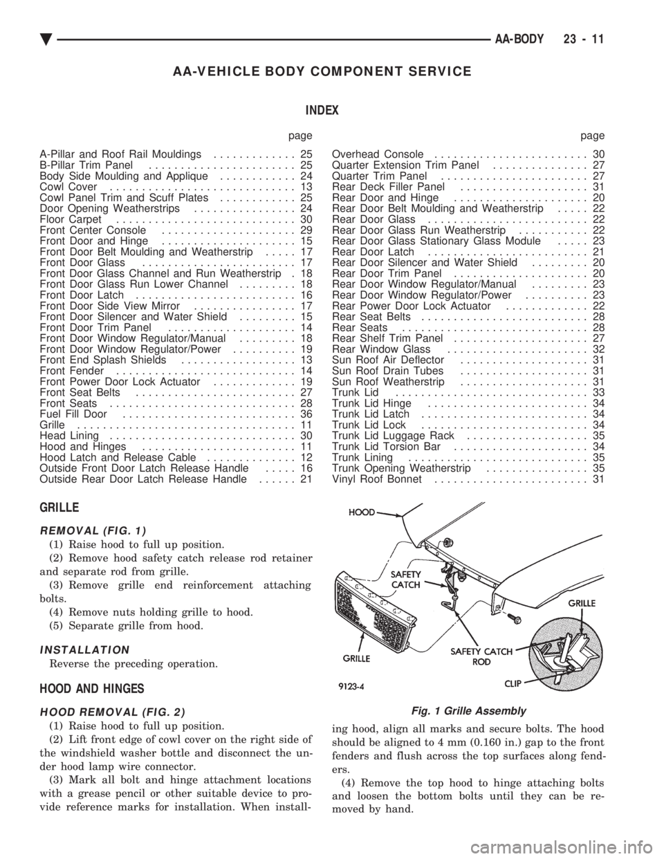
GRILLE
REMOVAL (FIG. 1)
(1) Raise hood to full up position.
(2) Remove hood safety catch release rod retainer
and separate rod from grille. (3) Remove grille end reinforcement attaching
bolts. (4) Remove nuts holding grille to hood.
(5) Separate grille from hood.
INSTALLATION
Reverse the preceding operation.
HOOD AND HINGES
HOOD REMOVAL (FIG. 2)
(1) Raise hood to full up position.
(2) Lift front edge of cowl cover on the right side of
the windshield washer bottle and disconnect the un-
der hood lamp wire connector. (3) Mark all bolt and hinge attachment locations
with a grease pencil or other suitable device to pro-
vide reference marks for installation. When install- ing hood, align all marks and secure bolts. The hood
should be aligned to 4 mm (0.160 in.) gap to the front
fenders and flush across the top surfaces along fend-
ers. (4) Remove the top hood to hinge attaching bolts
and loosen the bottom bolts until they can be re-
moved by hand.
Fig. 1 Grille Assembly
Ä AA-BODY 23 - 11
Page 2170 of 2438
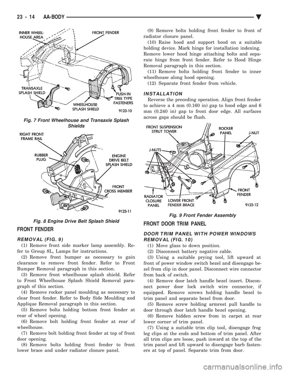
FRONT FENDER
REMOVAL (FIG. 9)
(1) Remove front side marker lamp assembly. Re-
fer to Group 8L, Lamps for instructions. (2) Remove front bumper as necessary to gain
clearance to remove front fender. Refer to Front
Bumper Removal paragraph in this section. (3) Remove front wheelhouse splash shield. Refer
to Front Wheelhouse Splash Shield Removal para-
graph of this section. (4) Remove rocker panel moulding as necessary to
clear front fender. Refer to Body Side Moulding and
Applique Removal paragraph in this section. (5) Remove bolts holding bottom front fender at
rear of wheel opening. (6) Remove bolt holding front fender at rear of
wheelhouse. (7) Remove bolt holding front fender at top of front
door opening. (8) Remove bolts holding front fender to front
lower brace and under radiator closure panel. (9) Remove bolts holding front fender to front of
radiator closure panel. (10) Raise hood and support hood on a suitable
holding device. Mark hinge for installation indexing.
Remove lower hood hinge attaching bolts and sepa-
rate hinge from front fender. Refer to Hood Hinge
Removal paragraph in this section. (11) Remove bolts holding front fender to inner
wheelhouse along hood opening. (12) Separate front fender from vehicle.
INSTALLATION
Reverse the preceding operation. Align front fender
to achiev ea4mm (0.160 in) gap to hood edge and 6
mm (0.240 in) gap to front door edge. All surfaces
across gaps should be flush.
FRONT DOOR TRIM PANEL
DOOR TRIM PANEL WITH POWER WINDOWS REMOVAL (FIG. 10)
(1) Move glass to down position.
(2) Disconnect battery negative cable.
(3) Using a suitable prying tool, lift upward at
front of power window switch bezel and disengage be-
zel from clip in door panel. Disconnect wire connector
from back of switch. (4) Remove door latch handle bezel insert. Discon-
nect power door lock switch wire connector, if
equipped. Remove screws holding handle bezel to
trim panel and separate bezel from door. (5) Remove screw holding armrest pull handle to
door through door latch handle bezel opening. (6) Remove hidden screw from in carpet at rear
lower corner of trim panel. (7) Using a suitable trim clip tool, disengage frog
leg clips at the ends and bottom of trim panel. After
all trim clips are loose, push inward at the top of the
trim panel and lift upward to disengage barb fasten-
ers at top of panel. Separate trim from door.
Fig. 7 Front Wheelhouse and Transaxle Splash Shields
Fig. 8 Engine Drive Belt Splash Shield
Fig. 9 Front Fender Assembly
23 - 14 AA-BODY Ä
Page 2171 of 2438
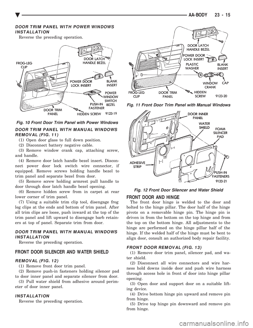
DOOR TRIM PANEL WITH POWER WINDOWS INSTALLATION
Reverse the preceding operation.
DOOR TRIM PANEL WITH MANUAL WINDOWSREMOVAL (FIG. 11)
(1) Open door glass to full down position.
(2) Disconnect battery negative cable.
(3) Remove window crank cap, attaching screw,
and handle. (4) Remove door latch handle bezel insert. Discon-
nect power door lock switch wire connector, if
equipped. Remove screws holding handle bezel to
trim panel and separate bezel from door. (5) Remove screw holding armrest pull handle to
door through door latch handle bezel opening. (6) Remove hidden screw from in carpet at rear
lower corner of trim panel. (7) Using a suitable trim clip tool, disengage frog
leg clips at the ends and bottom of trim panel. After
all trim clips are loose, push inward at the top of the
trim panel and lift upward to disengage barb retain-
ers at top of panel. Separate trim from door.
DOOR TRIM PANEL WITH MANUAL WINDOWS INSTALLATION
Reverse the preceding operation.
FRONT DOOR SILENCER AND WATER SHIELD
REMOVAL (FIG. 12)
(1) Remove front door trim panel.
(2) Remove push-in fasteners holding silencer pad
to door inner panel and separate silencer from door. (3) Pull water shield from adhesive around perim-
eter of door inner panel.
INSTALLATION
Reverse the preceding operation.
FRONT DOOR AND HINGE
The front door hinge is welded to the door and
bolted to the hinge pillar. The door half of the hinge
pivots on a removable hinge pin. The hinge pin is
driven in from the bottom on the top hinge and from
the top on the bottom hinge. All adjustments to the
hinge are performed on the hinge pillar half of the
hinge. If the welded half of the hinge must be bent to
align door, consult an authorized body repair facility.
FRONT DOOR REMOVAL (FIG. 13)
(1) Remove door trim panel, silencer pad, and wa-
ter shield. (2) Disconnect all wire connectors and wire har-
ness hold downs inside door and push wire harness
through access hole in front of door into hinge pillar
opening. (3) Open door and support door on a suitable lift-
ing device. (4) Drive bottom hinge pin upward and remove pin
from hinge. (5) Drive top hinge pin downward and remove pin
from hinge.
Fig. 10 Front Door Trim Panel with Power Windows
Fig. 11 Front Door Trim Panel with Manual Windows
Fig. 12 Front Door Silencer and Water Shield
Ä AA-BODY 23 - 15
Page 2172 of 2438
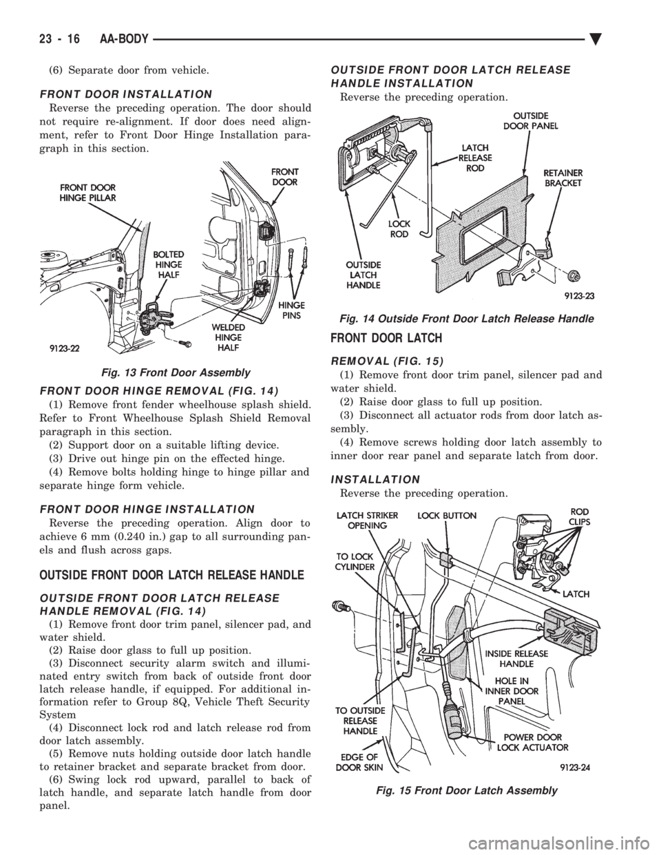
(6) Separate door from vehicle.
FRONT DOOR INSTALLATION
Reverse the preceding operation. The door should
not require re-alignment. If door does need align-
ment, refer to Front Door Hinge Installation para-
graph in this section.
FRONT DOOR HINGE REMOVAL (FIG. 14)
(1) Remove front fender wheelhouse splash shield.
Refer to Front Wheelhouse Splash Shield Removal
paragraph in this section. (2) Support door on a suitable lifting device.
(3) Drive out hinge pin on the effected hinge.
(4) Remove bolts holding hinge to hinge pillar and
separate hinge form vehicle.
FRONT DOOR HINGE INSTALLATION
Reverse the preceding operation. Align door to
achieve 6 mm (0.240 in.) gap to all surrounding pan-
els and flush across gaps.
OUTSIDE FRONT DOOR LATCH RELEASE HANDLE
OUTSIDE FRONT DOOR LATCH RELEASE HANDLE REMOVAL (FIG. 14)
(1) Remove front door trim panel, silencer pad, and
water shield. (2) Raise door glass to full up position.
(3) Disconnect security alarm switch and illumi-
nated entry switch from back of outside front door
latch release handle, if equipped. For additional in-
formation refer to Group 8Q, Vehicle Theft Security
System (4) Disconnect lock rod and latch release rod from
door latch assembly. (5) Remove nuts holding outside door latch handle
to retainer bracket and separate bracket from door. (6) Swing lock rod upward, parallel to back of
latch handle, and separate latch handle from door
panel.
OUTSIDE FRONT DOOR LATCH RELEASE
HANDLE INSTALLATION
Reverse the preceding operation.
FRONT DOOR LATCH
REMOVAL (FIG. 15)
(1) Remove front door trim panel, silencer pad and
water shield. (2) Raise door glass to full up position.
(3) Disconnect all actuator rods from door latch as-
sembly. (4) Remove screws holding door latch assembly to
inner door rear panel and separate latch from door.
INSTALLATION
Reverse the preceding operation.
Fig. 13 Front Door Assembly
Fig. 14 Outside Front Door Latch Release Handle
Fig. 15 Front Door Latch Assembly
23 - 16 AA-BODY Ä
Page 2175 of 2438
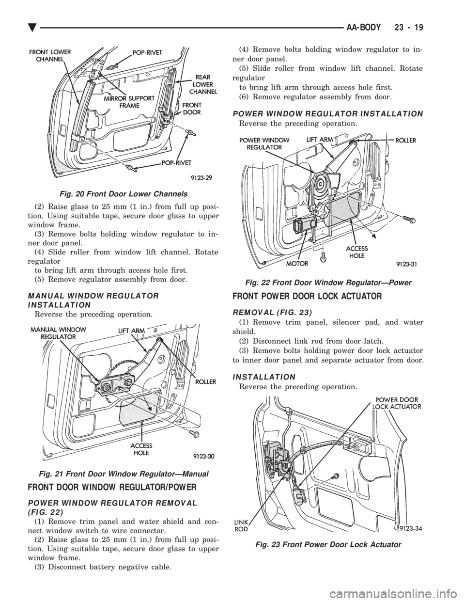
(2) Raise glass to 25 mm (1 in.) from full up posi-
tion. Using suitable tape, secure door glass to upper
window frame. (3) Remove bolts holding window regulator to in-
ner door panel. (4) Slide roller from window lift channel. Rotate
regulator to bring lift arm through access hole first.
(5) Remove regulator assembly from door.
MANUAL WINDOW REGULATOR INSTALLATION
Reverse the preceding operation.
FRONT DOOR WINDOW REGULATOR/POWER
POWER WINDOW REGULATOR REMOVAL(FIG. 22)
(1) Remove trim panel and water shield and con-
nect window switch to wire connector. (2) Raise glass to 25 mm (1 in.) from full up posi-
tion. Using suitable tape, secure door glass to upper
window frame. (3) Disconnect battery negative cable. (4) Remove bolts holding window regulator to in-
ner door panel. (5) Slide roller from window lift channel. Rotate
regulator to bring lift arm through access hole first.
(6) Remove regulator assembly from door.
POWER WINDOW REGULATOR INSTALLATION
Reverse the preceding operation.
FRONT POWER DOOR LOCK ACTUATOR
REMOVAL (FIG. 23)
(1) Remove trim panel, silencer pad, and water
shield. (2) Disconnect link rod from door latch.
(3) Remove bolts holding power door lock actuator
to inner door panel and separate actuator from door.
INSTALLATION
Reverse the preceding operation.
Fig. 20 Front Door Lower Channels
Fig. 21 Front Door Window RegulatorÐManual
Fig. 22 Front Door Window RegulatorÐPower
Fig. 23 Front Power Door Lock Actuator
Ä AA-BODY 23 - 19