1993 CHEVROLET PLYMOUTH ACCLAIM door lock
[x] Cancel search: door lockPage 731 of 2438

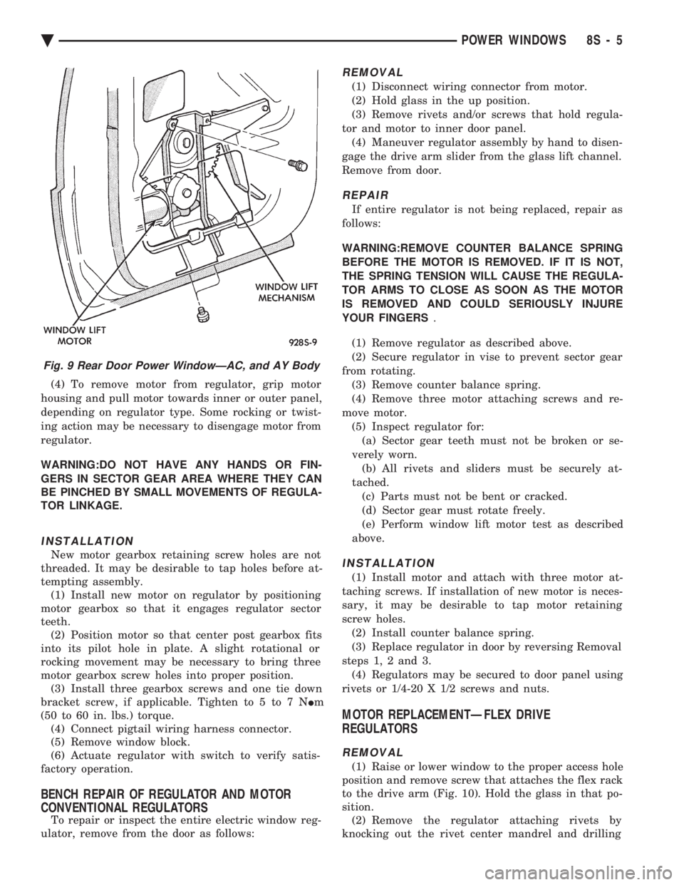
(4) To remove motor from regulator, grip motor
housing and pull motor towards inner or outer panel,
depending on regulator type. Some rocking or twist-
ing action may be necessary to disengage motor from
regulator.
WARNING:DO NOT HAVE ANY HANDS OR FIN-
GERS IN SECTOR GEAR AREA WHERE THEY CAN
BE PINCHED BY SMALL MOVEMENTS OF REGULA-
TOR LINKAGE.
INSTALLATION
New motor gearbox retaining screw holes are not
threaded. It may be desirable to tap holes before at-
tempting assembly. (1) Install new motor on regulator by positioning
motor gearbox so that it engages regulator sector
teeth. (2) Position motor so that center post gearbox fits
into its pilot hole in plate. A slight rotational or
rocking movement may be necessary to bring three
motor gearbox screw holes into proper position. (3) Install three gearbox screws and one tie down
bracket screw, if applicable. Tighten to 5 to 7 N Im
(50 to 60 in. lbs.) torque. (4) Connect pigtail wiring harness connector.
(5) Remove window block.
(6) Actuate regulator with switch to verify satis-
factory operation.
BENCH REPAIR OF REGULATOR AND MOTOR
CONVENTIONAL REGULATORS
To repair or inspect the entire electric window reg-
ulator, remove from the door as follows:
REMOVAL
(1) Disconnect wiring connector from motor.
(2) Hold glass in the up position.
(3) Remove rivets and/or screws that hold regula-
tor and motor to inner door panel. (4) Maneuver regulator assembly by hand to disen-
gage the drive arm slider from the glass lift channel.
Remove from door.
REPAIR
If entire regulator is not being replaced, repair as
follows:
WARNING:REMOVE COUNTER BALANCE SPRING
BEFORE THE MOTOR IS REMOVED. IF IT IS NOT,
THE SPRING TENSION WILL CAUSE THE REGULA-
TOR ARMS TO CLOSE AS SOON AS THE MOTOR
IS REMOVED AND COULD SERIOUSLY INJURE
YOUR FINGERS .
(1) Remove regulator as described above.
(2) Secure regulator in vise to prevent sector gear
from rotating. (3) Remove counter balance spring.
(4) Remove three motor attaching screws and re-
move motor. (5) Inspect regulator for:(a) Sector gear teeth must not be broken or se-
verely worn. (b) All rivets and sliders must be securely at-
tached. (c) Parts must not be bent or cracked.
(d) Sector gear must rotate freely.
(e) Perform window lift motor test as described
above.
INSTALLATION
(1) Install motor and attach with three motor at-
taching screws. If installation of new motor is neces-
sary, it may be desirable to tap motor retaining
screw holes. (2) Install counter balance spring.
(3) Replace regulator in door by reversing Removal
steps 1, 2 and 3. (4) Regulators may be secured to door panel using
rivets or 1/4-20 X 1/2 screws and nuts.
MOTOR REPLACEMENTÐFLEX DRIVE
REGULATORS
REMOVAL
(1) Raise or lower window to the proper access hole
position and remove screw that attaches the flex rack
to the drive arm (Fig. 10). Hold the glass in that po-
sition. (2) Remove the regulator attaching rivets by
knocking out the rivet center mandrel and drilling
Fig. 9 Rear Door Power WindowÐAC, and AY Body
Ä POWER WINDOWS 8S - 5
Page 734 of 2438

INSTALLATION
(1) Install motor into housing with one stud and in
center of housing to secure motor to housing. (2) Before installing new spring, power the motor
into the full-up position. (3) Replace assist spring on cable housing. Wind
spring counter clockwise 3 1/2 turns on the left door.
The right door, wind spring clockwise 3 1/2 turns
(Fig. 19).
(4) Install the other two studs and nuts and
tighten to 4 to 5 M Im (35 to 45 in. lbs.) torque.
(5) Inspect that cables are not twisted prior to in-
stalling motor and housing into door.
QUARTER WINDOW REPLACEMENTÐAJ BODY
For steps (1) through (5) refer to Group 23, Body,
for complete procedures. (1) Remove the folding top sling well assembly.
(2) Remove the quarter trim upper moldings.
(3) Remove the cowl trim and scuff plate panels.
(4) Remove the rear seat cushion.
(5) Remove the quarter trim and rear seat back as-
sembly. (6) Remove quarter windows assembly (Fig. 20).
Fig. 16 Separating Motor from Housing
Fig. 17 Cable/Drum and Motor
Fig. 18 Assist Spring Cover
Fig. 19 Wind Assist Spring Cover
Fig. 20 Power Quarter WindowÐAJ Body
8S - 8 POWER WINDOWS Ä
Page 737 of 2438

POWER MIRRORS
CONTENTS
page page
AUTOMATIC DAY/NIGHT INSIDE MIRROR .... 7
AUTOMATIC DAY/NIGHT INSIDE MIRROR WITH ULTRALIGHT HEADLAMP CONTROL ....... 7
GENERAL INFORMATION .................. 1
HEATED MIRROR ........................ 2
INSIDE MIRROR/READING LAMPS BULB/LENS REPLACEMENT ........................ 6
INSIDE MIRROR/READING LAMPS REPLACEMENT ........................ 6
MIRROR ASSEMBLY REPLACEMENTÐAA BODY.5
MIRROR ASSEMBLY REPLACEMENTÐ AC AND AY BODIES .................... 5
MIRROR ASSEMBLY REPLACEMENTÐAG BODY.5
MIRROR ASSEMBLY REPLACEMENTÐAJ BODY.5
MIRROR ASSEMBLY REPLACEMENTÐAP BODY.5
MIRROR MOTOR TEST PROCEDURE ........ 2
MIRROR SWITCH REPLACEMENTÐAA BODY . 3
MIRROR SWITCH REPLACEMENTÐAC AND AY BODIES .............................. 4
MIRROR SWITCH REPLACEMENTÐAG AND AJ BODIES .............................. 3
MIRROR SWITCH REPLACEMENTÐAP BODY . 4
MIRROR SWITCH TEST PROCEDURE ....... 2
TEST PROCEDURES ...................... 2
GENERAL INFORMATION
Electrically operated power mirrors are available
on all car lines. The mirrors are controlled by a sin-
gle switch assembly located either on the driver's
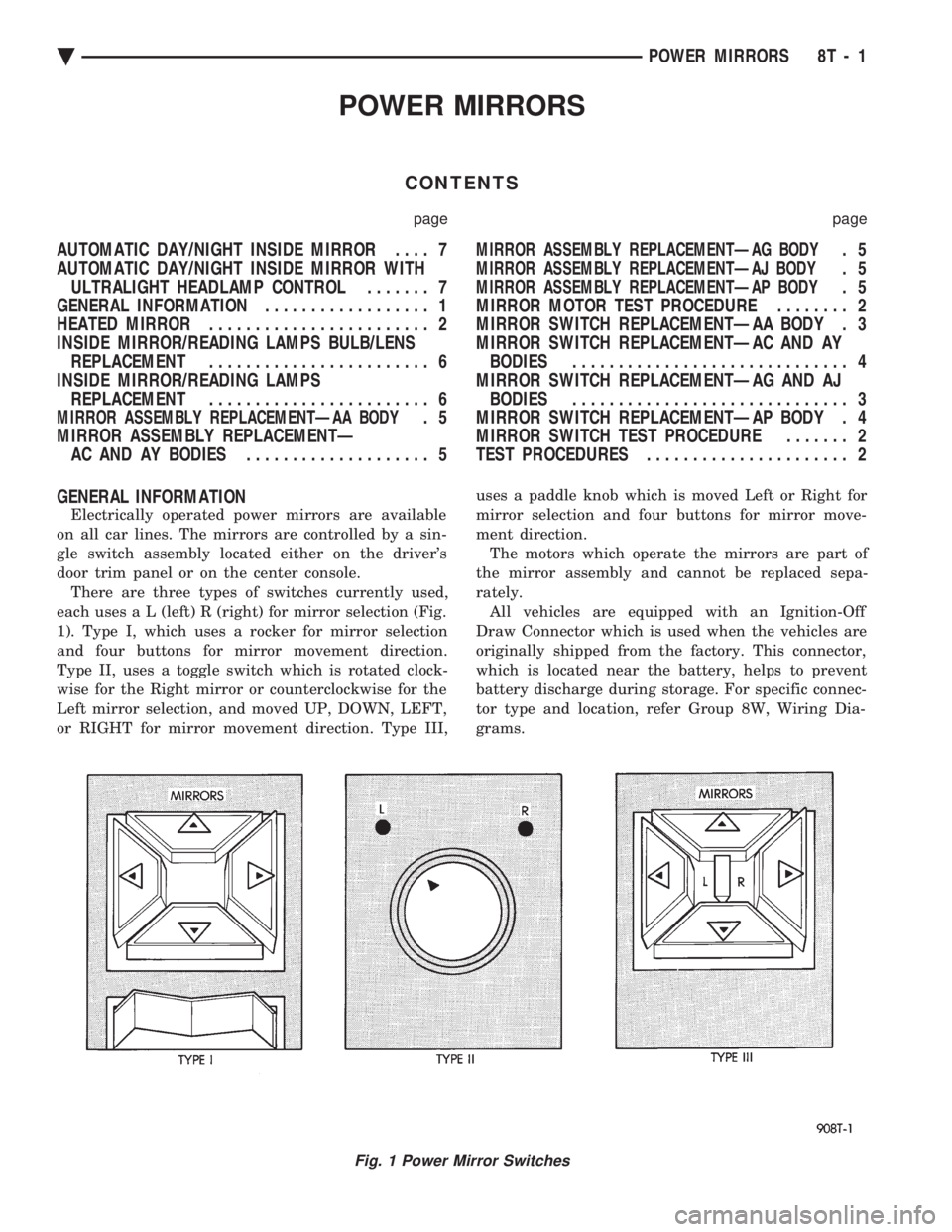
door trim panel or on the center console. There are three types of switches currently used,
each use s a L (left) R (right) for mirror selection (Fig.
1). Type I, which uses a rocker for mirror selection
and four buttons for mirror movement direction.
Type II, uses a toggle switch which is rotated clock-
wise for the Right mirror or counterclockwise for the
Left mirror selection, and moved UP, DOWN, LEFT,
or RIGHT for mirror movement direction. Type III, uses a paddle knob which is moved Left or Right for
mirror selection and four buttons for mirror move-
ment direction.
The motors which operate the mirrors are part of
the mirror assembly and cannot be replaced sepa-
rately. All vehicles are equipped with an Ignition-Off
Draw Connector which is used when the vehicles are
originally shipped from the factory. This connector,
which is located near the battery, helps to prevent
battery discharge during storage. For specific connec-
tor type and location, refer Group 8W, Wiring Dia-
grams.
Fig. 1 Power Mirror Switches
Ä POWER MIRRORS 8T - 1
Page 742 of 2438

(3) Disconnect mirror wiring connector near bot-
tom of door (Fig. 19). (4) Remove two mirror retaining nuts and screw
one, and pull mirror and harness from door. (5) For installation, reverse above procedure. Test
mirror for proper operation before installing door
trim panel.
INSIDE MIRROR/READING LAMPS REPLACEMENT
(1) Release locking tab on front side of mirror stay
by pushing down. While holding tab down, pull mir-
ror rearward to remove (Fig. 20). (2) Remove visor center attaching clips.
(3) Remove header end caps.
(4) Remove header trim.
(5) Disconnect wiring connector.
(6) For installation, reverse above procedure. En-
sure the mirror is fully locked into place.
INSIDE MIRROR/READING LAMPS BULB/LENS
REPLACEMENT
(1) Place a small thin blade tool in the notch at
the outside end of the lens housing and pry off the
lens housing. (2) Remove lamp socket from lens housing. Re-
move bulb from socket and replace if necessary. (3) Remove lens by applying pressure on locking
tabs to remove lens. (4) Replacing lens, set into place apply pressure
until it is locked into position. (5) For installation, reverse above procedure.
Fig. 16 Power Mirror AssemblyÐAJ Body
Fig. 17 Power Mirror WiringÐAP Body
Fig. 18 Power Mirror AssemblyÐAP Body
Fig. 19 Power Mirror AssemblyÐAC and AY Body
8T - 6 POWER MIRRORS Ä
Page 769 of 2438

WIRING AND COMPONENT IDENTIFICATION
CONTENTS
page page
AA BODY C, D, P ...................... 19
AC BODY C,D ......................... 37
AG BODY ............................. 61 AJ BODY
.............................. 77
AP BODY D, P ......................... 94
AY BODY-C ........................... 111
The wiring and components shown in this section
are divided into groups by vehicle line. When locat-
ing a specific harness routing or component, first
turn to the appropriate index, then look up the fig-
ure number that applies.Page numbers at the top of each page do not refer to figure numbers.
Throughout this section references may be made to
a particular vehicle by letter or number designation.
A chart showing the breakdown of these is shown in
the general information section.
AA BODY C, D, P
Caption Fig.
Anti Lock Brake System Wiring .....................4
Body Left Side Wiring ...........................6
Body Right Side Wiring ..........................5
Deck Lid Wiring ..............................1
Door Wiring (Body Side) .........................7
Door Wiring (Front) ............................8
Door Wiring (Rear) ............................9
Engine Compartment Wiring ......................16
Engine Wiring 2.5L ............................19
Engine Wiring 2.5L Flex Fuel ......................20Caption Fig.
Engine Wiring 3.0L ............................21
Front End Lighting ............................22
Ground Strap Locations .........................15
Instrument Panel Wiring .................. .11, 12, 13
Rear End Wiring ..............................2
Steering Column Wiring .........................10
Transmission Wiring ...........................17
Transmission Wiring ETAX .......................18
Trunk Wiring ................................3
Underhood Lamp Wiring ........................14
Ä WIRING AND COMPONENT IDENTIFICATION 8W - 19
Page 811 of 2438

AG BODY
Caption Fig.
Anti Lock Brake System Wiring .....................6
Body Left Side Wiring ...........................5
Body Right Side Wiring ..........................4
Console Wiring ...............................9
Door Wiring .................................8
Door Wiring (Body Side) .........................7
Engine Compartment Wiring ......................14
Engine Wiring 2.5L EFI .........................17
Engine Wiring 3.0L ............................20
Engine Wiring Turbo III ..................... .18, 19
Front End Wiring .............................22Caption Fig.
Ground Strap Location .........................21
Instrument Panel Wiring (Connections) ...............11
Instrument Panel Wiring (Routing) ..................10
Liftgate Wiring ...............................2
Rear End Wiring ..............................1
Roof Wiring .................................3
Steering Column Wiring .........................12
Transmission Wiring ...........................15
Transmission Wiring 41TE .......................16
Underhood Lamp Wiring ........................13
Ä WIRING AND COMPONENT IDENTIFICATION 8W - 61
Page 815 of 2438

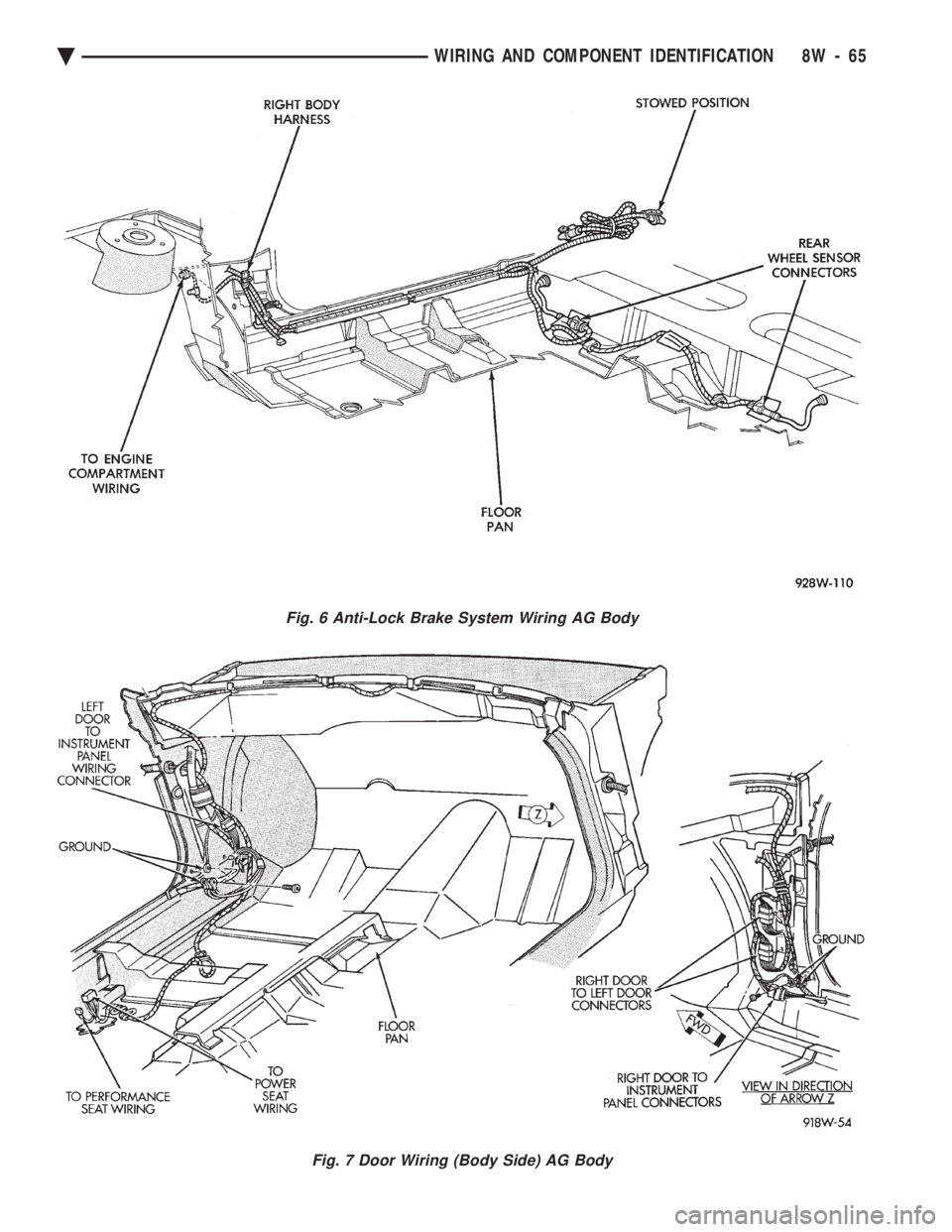
Fig. 6 Anti-Lock Brake System Wiring AG Body
Fig. 7 Door Wiring (Body Side) AG Body
Ä WIRING AND COMPONENT IDENTIFICATION 8W - 65
Page 827 of 2438

AJ BODY
Caption Fig.
Anti-Lock Brake System Wiring .....................8
Body Left Side Wiring (AJ-27) .....................7
Body Left Side Wiring ...........................5
Body Right Side Wiring ..........................6
Console Wiring ...............................9
Deck Lid Wiring ..............................3
Door Wiring (Body Side) ........................10
Door Wiring ................................11
Engine Compartment Wiring ......................15
Engine Wiring EFI ............................18
Engine Wiring 3.0L ............................19Caption Fig.
Front End Wiring .............................22
Ground Strap Locations .........................21
Heated Rear Window Wiring .......................4
Instrument Panel Wiring (Connections) ...............14
Instrument Panel Wiring (Routing) ..................13
Rear End Wiring ..............................1
Steering Column Wiring .........................12
Transmission Wiring ...........................16
Transmission Wiring 41TE .......................17
Trunk Wiring ................................2
Underhood Lamp Wiring ........................20
Ä WIRING AND COMPONENT IDENTIFICATION 8W - 77