1993 CHEVROLET PLYMOUTH ACCLAIM windshield wipers
[x] Cancel search: windshield wipersPage 621 of 2438
WINDSHIELD WIPER AND WASHER SYSTEMS
CONTENTS
page page
GENERAL WIPER INFORMATION ........... 1
INTERMITTENT WINDSHIELD WIPER MOTOR AND SWITCH SERVICE PROCEDURES .... 12
WINDSHIELD WASHERS ................. 17 WINDSHIELD WIPER BLADE AND ARM SERVICE
PROCEDURES ......................... 1
WINDSHIELD WIPER MOTOR AND LINKAGE ASSEMBLY SERVICE PROCEDURES ....... 3
GENERAL WIPER INFORMATION
WARNING: ON VEHICLES EQUIPPED WITH AIR-
BAG, SEE GROUP 8M, RESTRAINT SYSTEMS FOR
STEERING WHEEL OR COLUMN REMOVAL PROCE-
DURES.
The windshield wipers can be operated with the
windshield wiper switch only when the ignition
switch is in the ACCESSORY or IGNITION position.
A fuse, located in the fuse block, protects the cir-
cuitry of the wiper system and the vehicle. The wiper motor has permanent magnet fields. The speeds are determined by current flow to the appro-
priate set of brushes. The intermittent wipe system, in addition to low
and high speed, has a delay mode. The delay mode
has a range of 2 to 15 seconds. This is accomplished
by a variable resistor in the wiper switch and is con-
trolled electrically by a relay. The wiper system completes the wipe cycle when
the switch is turned OFF. The blades park in the
lowest portion of the wipe pattern.
WINDSHIELD WIPER BLADE AND ARM SERVICE PROCEDURES
WIPER BLADES
Wiper blades, exposed to the weather for a long pe-
riod of time, tend to lose their wiping effectiveness.
Periodic cleaning of the wiper blade is suggested to
remove the accumulation of salt and road film. The
wiper blades, arms, and windshield should be cleaned
with a sponge or cloth and a mild detergent or nona-
brasive cleaner. If the blades continue to streak or
smear, they should be replaced.
WIPER BLADE ELEMENT CHANGE
(1) Turn wiper switch ON, position blades to a con-
venient place by turning the ignition switch ON and
OFF. (2) Lift wiper arm to raise blade off glass.
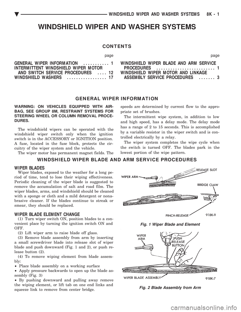
(3) Remove blade assembly from arm by inserting
a small screwdriver blade into release slot of wiper
blade and push downward (Fig. 1 and 2), or push re-
lease button (2). (4) To remove wiping element from blade assem-
bly:
² Place blade assembly on a working surface
² Apply pressure backwards to open up the blade as-
sembly (Fig. 3)
² By pushing downward and pulling away remove
the wiping element, or lift tab on one end links and
squeeze link to remove from center bridge.
Fig. 1 Wiper Blade and Element
Fig. 2 Blade Assembly from Arm
Ä WINDSHIELD WIPER AND WASHER SYSTEMS 8K - 1
Page 623 of 2438
(3) Secure arm to pivot with attaching nut and
tighten 17 to 22 N Im (155 to 195 in. lbs.) torque.
(4) Close head cover and remove pin from arm pin
hole.
WIPER ARM ADJUSTMENT
FRONT ARM ADJUSTMENT
(1) Cycle the wiper motor into the PARK position.
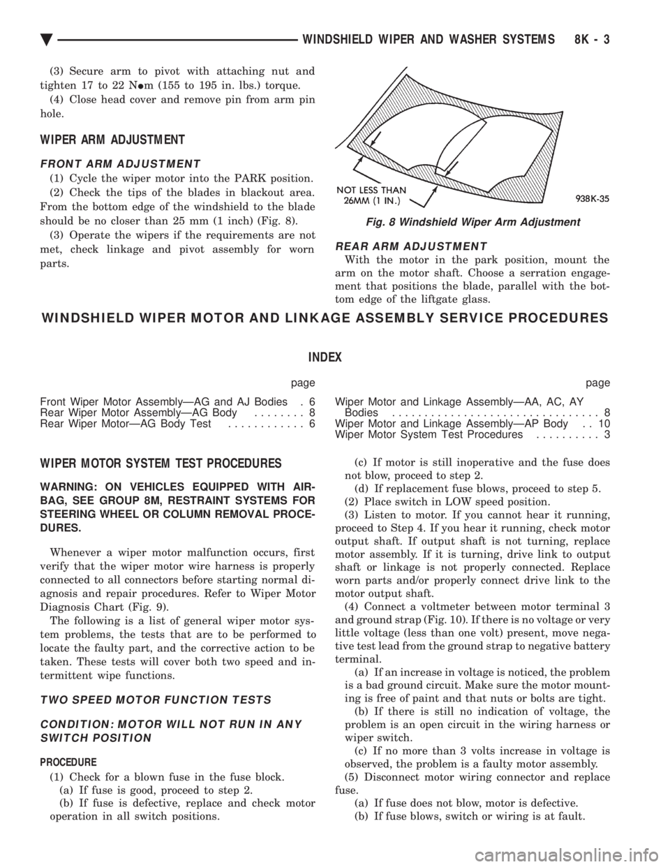
(2) Check the tips of the blades in blackout area.
From the bottom edge of the windshield to the blade
should be no closer than 25 mm (1 inch) (Fig. 8). (3) Operate the wipers if the requirements are not
met, check linkage and pivot assembly for worn
parts.
REAR ARM ADJUSTMENT
With the motor in the park position, mount the
arm on the motor shaft. Choose a serration engage-
ment that positions the blade, parallel with the bot-
tom edge of the liftgate glass.
WINDSHIELD WIPER MOTOR AND LINKAGE ASSEMBLY SERVICE PROCEDURES
INDEX
page page
Front Wiper Motor AssemblyÐAG and AJ Bodies . 6
Rear Wiper Motor AssemblyÐAG Body ........ 8
Rear Wiper MotorÐAG Body Test ............ 6 Wiper Motor and Linkage AssemblyÐAA, AC, AY
Bodies ................................ 8
Wiper Motor and Linkage AssemblyÐAP Body . . 10
Wiper Motor System Test Procedures .......... 3
WIPER MOTOR SYSTEM TEST PROCEDURES
WARNING: ON VEHICLES EQUIPPED WITH AIR-
BAG, SEE GROUP 8M, RESTRAINT SYSTEMS FOR
STEERING WHEEL OR COLUMN REMOVAL PROCE-
DURES.
Whenever a wiper motor malfunction occurs, first
verify that the wiper motor wire harness is properly
connected to all connectors before starting normal di-
agnosis and repair procedures. Refer to Wiper Motor
Diagnosis Chart (Fig. 9). The following is a list of general wiper motor sys-
tem problems, the tests that are to be performed to
locate the faulty part, and the corrective action to be
taken. These tests will cover both two speed and in-
termittent wipe functions.
TWO SPEED MOTOR FUNCTION TESTS
CONDITION: MOTOR WILL NOT RUN IN ANY SWITCH POSITION
PROCEDURE
(1) Check for a blown fuse in the fuse block. (a) If fuse is good, proceed to step 2.
(b) If fuse is defective, replace and check motor
operation in all switch positions. (c) If motor is still inoperative and the fuse does
not blow, proceed to step 2. (d) If replacement fuse blows, proceed to step 5.
(2) Place switch in LOW speed position.
(3) Listen to motor. If you cannot hear it running,
proceed to Step 4. If you hear it running, check motor
output shaft. If output shaft is not turning, replace
motor assembly. If it is turning, drive link to output
shaft or linkage is not properly connected. Replace
worn parts and/or properly connect drive link to the
motor output shaft. (4) Connect a voltmeter between motor terminal 3
and ground strap (Fig. 10). If there is no voltage or very
little voltage (less than one volt) present, move nega-
tive test lead from the ground strap to negative battery
terminal. (a) If an increase in voltage is noticed, the problem
is a bad ground circuit. Make sure the motor mount-
ing is free of paint and that nuts or bolts are tight. (b) If there is still no indication of voltage, the
problem is an open circuit in the wiring harness or
wiper switch. (c) If no more than 3 volts increase in voltage is
observed, the problem is a faulty motor assembly.
(5) Disconnect motor wiring connector and replace
fuse. (a) If fuse does not blow, motor is defective.
(b) If fuse blows, switch or wiring is at fault.
Fig. 8 Windshield Wiper Arm Adjustment
Ä WINDSHIELD WIPER AND WASHER SYSTEMS 8K - 3
Page 626 of 2438
CONDITION: MOTOR WILL STOP WHEREVER IT IS, WHEN COLUMN SWITCH IS PUT IN OFFPOSITION. THE WIPERS DO NOT CONTINUERUNNING TO PARK POSITION
PROCEDURE
(1) Remove motor wiring connector and clean ter-
minals. Reconnect connector and test motor.If prob-
lem persists, proceed to Step 2. (2) Set wiper switch to OFF position. Disconnect
motor wiring connector. Connect a voltmeter or test
lamp to the motor ground strap. Connect the other
lead to terminal 2 of wiring connector. (a) If voltage is not present, check for an open
circuit in the wiring harness or wiper control
switch. (b) If voltage is present, proceed to step 3.
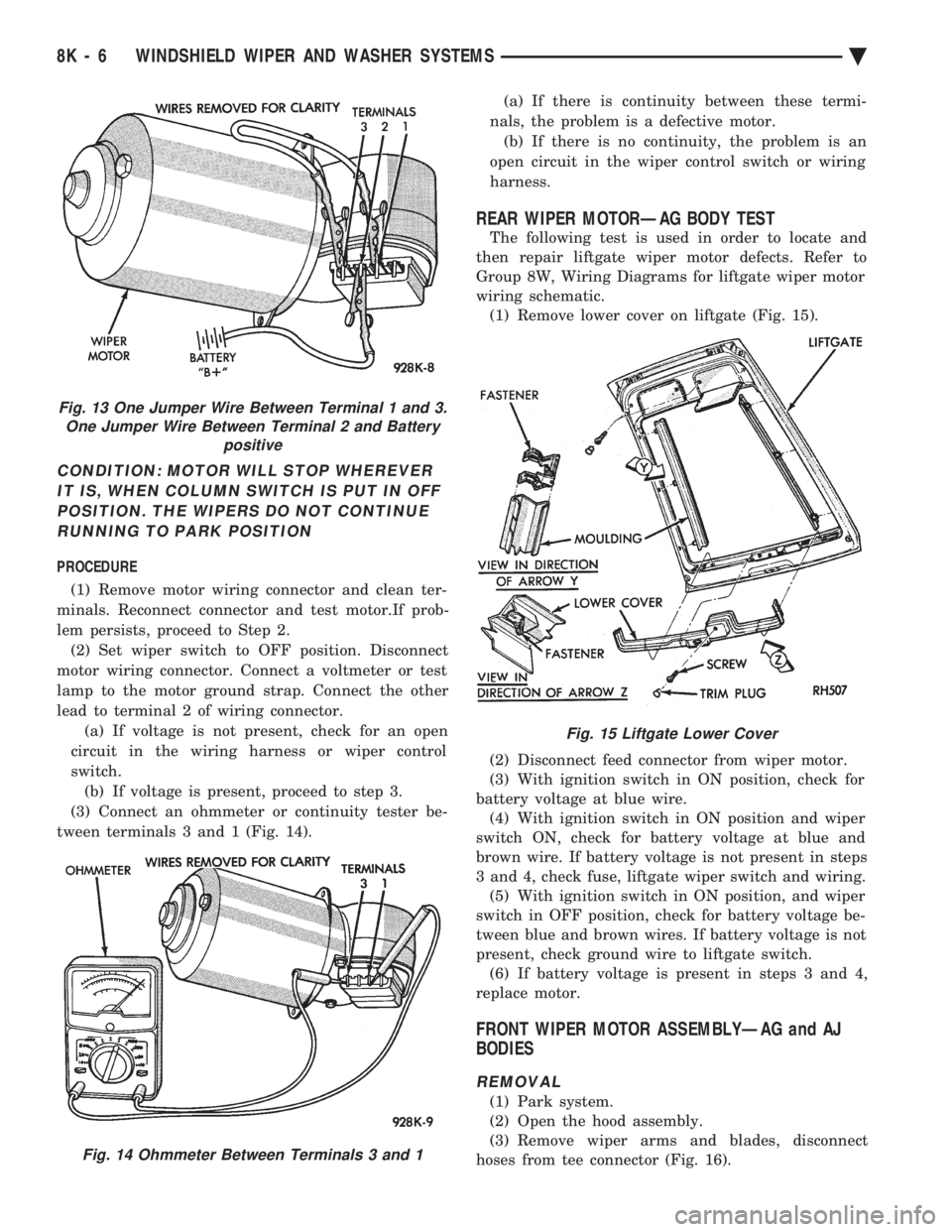
(3) Connect an ohmmeter or continuity tester be-
tween terminals 3 and 1 (Fig. 14). (a) If there is continuity between these termi-
nals, the problem is a defective motor. (b) If there is no continuity, the problem is an
open circuit in the wiper control switch or wiring
harness.
REAR WIPER MOTORÐAG BODY TEST
The following test is used in order to locate and
then repair liftgate wiper motor defects. Refer to
Group 8W, Wiring Diagrams for liftgate wiper motor
wiring schematic. (1) Remove lower cover on liftgate (Fig. 15).
(2) Disconnect feed connector from wiper motor.
(3) With ignition switch in ON position, check for
battery voltage at blue wire. (4) With ignition switch in ON position and wiper
switch ON, check for battery voltage at blue and
brown wire. If battery voltage is not present in steps
3 and 4, check fuse, liftgate wiper switch and wiring. (5) With ignition switch in ON position, and wiper
switch in OFF position, check for battery voltage be-
tween blue and brown wires. If battery voltage is not
present, check ground wire to liftgate switch. (6) If battery voltage is present in steps 3 and 4,
replace motor.
FRONT WIPER MOTOR ASSEMBLYÐAG and AJ
BODIES
REMOVAL
(1) Park system.
(2) Open the hood assembly.
(3) Remove wiper arms and blades, disconnect
hoses from tee connector (Fig. 16).
Fig. 13 One Jumper Wire Between Terminal 1 and 3. One Jumper Wire Between Terminal 2 and Battery positive
Fig. 14 Ohmmeter Between Terminals 3 and 1
Fig. 15 Liftgate Lower Cover
8K - 6 WINDSHIELD WIPER AND WASHER SYSTEMS Ä
Page 632 of 2438

INTERMITTENT WINDSHIELD WIPER MOTOR AND SWITCH SERVICE PROCEDURES
INDEX
page page
Intermittent Windshield Wiper Switch Tests ..... 12
Intermittent Wipe Switch Test ............... 14
Intermittent Wiper Function Tests ............ 14
Intermittent Wiper Motor System Test ......... 12 Pulse Intermittent Windshield Wiper Controller
(PIWWC) .............................. 15
Standard Wiper Switch Test ................ 14
Wiper Switch Service Procedure ............. 15
INTERMITTENT WIPER MOTOR SYSTEM TEST
Intermittent Wiper Motor Service Procedures for
diagnosis of problems which do not involve the delay
function, refer to the Two-Speed Motor Function
Tests. The two-speed functions of all wiper motors
are identical. If a problem occurs, only in the DELAY mode, the
following tests are to be performed.
INTERMITTENT WINDSHIELD WIPER SWITCH
TESTS
WARNING: ON VEHICLES EQUIPPED WITH AIR-
BAG, SEE GROUP 8M, RESTRAINT SYSTEMS FOR
STEERING WHEEL OR COLUMN REMOVAL PROCE-
DURES.
The intermittent wipe function on AC, AG, AJ and
AY vehicles is controlled by the body controller, lo-
cated in the passenger compartment behind the right
side kick panel (Fig. 22). If the body controller is de-
termined to be the problem, refer to Group 8E, In-
strument Panels and Gauges, for replacement
procedures.
CONDITION: WIPERS DO NOT COME ON WHEN THE SWITCH IS IN DELAY POSITION
PROCEDURE
(1) Disconnect 25-way connector (blue) from the
body controller. (2) Place wiper control switch in maximum DE-
LAY position. (3) Connect positive lead of voltmeter to pin 9 of
connector (blue) and negative lead to the good
ground. (a) If voltmeter reads 0, check control switch and
wiring for an open circuit. (b) If voltmeter reads 10 to 15 volts, proceed to
step 4.
(4) Connect positive lead of voltmeter to pin 22 of
blue connector and negative lead to a good ground. (a) If voltmeter reads 0, check fuses and wiring
for an open circuit. (b) If voltmeter reads 10 to 15 volts, reconnect
body controller and proceed to step 5.
(5) Connect positive lead of voltmeter to pin 24 of
blue connector and negative lead to the metal case of
the body controller. Disconnect wiring harness from
wiper motor. Set control switch to the minimum de-
lay mode. (a) If voltmeter reads 0, check wiring from the
intermittent wipe switch to body controller for an
open circuit. (b) If voltmeter reads 10 to 15 volts, proceed to
step 6.
(6) Connect voltmeter to pin L of the Intermittent
wiper switch. Place intermittent wiper switch in the
Max. Delay position. (a) If voltmeter reads zero volts, change the in-
termittent wiper switch. (b) If voltmeter reads 10-15 volts, check the wir-
ing harness from the intermittent wiper switch to
the wiper motor for an open circuit.
(7) If all tests above have been performed and the
problem was not found, replace the body controller.
Fig. 22 Body Controller Location
8K - 12 WINDSHIELD WIPER AND WASHER SYSTEMS Ä
Page 633 of 2438

CONDITION: WIPERS START TO WIPE, BUT STOP BEFORE ONE COMPLETE CYCLE ANDDO NOT RETURN TO PARK POSITION
PROCEDURE
(1) Verify that motor will park when the column
switch is put in the OFF position. (2) Set wiper control switch to maximum DELAY
and allow motor to run until it stops during the wipe
cycle. When motor stops, disconnect 25-way blue con-
nector from the body controller. (3) Connect positive lead of voltmeter to pin 20 of
blue connector and negative lead to the metal case of
the body controller. (a) If voltmeter reads 0, check wiring for an open
circuit. (b) If voltmeter reads 10 to 15 volts, proceed to
step 4.
(4) Using an ohmmeter or continuity tester; (a) Check for continuity between pins 20 and 24
of blue connector of the body controller. (b) Reverse ohmmeter leads on pins 20 and 24,
again checking for continuity. (c) If continuity between pins 20 and 24 is not
observed in both steps a and b, replace the body
controller.
CONDITION: EXCESSIVE DELAY OF MORE THAN 30 SECONDS OR INADEQUATEVARIATION IN DELAY
PROCEDURE
(1) Variations in delay should be as follows: (a) Minimum delay control to extreme counter-
clockwise position before first detent of 1/2 to 2 sec-
onds. (b) Maximum delay control to extreme clockwise
position before OFF detent of 15 to 25 seconds.
(2) If there is excessive delay or no variations in
delay, remove the wiper motor wiring harness while
the motor is parked in the OFF position. (3) Remove 25-way blue connector from the body
controller. (4) Set wiper control switch to maximum DELAY
position. (5) With ignition switch in ON position, measure
voltage between pin 9 of black connector and a good
ground. (a) If voltmeter reads 0, proceed to step 6.
(b) If voltmeter reads 10 to 15 volts, proceed to
step 7.
(6) Set wiper control switch to minimum DELAY
position and measure voltage between pin 9 of blue
connector and a good ground. If voltmeter reads 0,
check for an open circuit in the intermittent wipe
wiring harness. (7) Remove wiper motor circuit fuse. (8) Using an ohmmeter, measure the resistance be-
tween pins 9 and 22 of the body controller 25-way
black connector. Set the wiper control switch first to
minimum DELAY and then maximum DELAY. (a) If resistance reading at minimum DELAY
setting is between 0 and 15 ohms, and at maxi-
mum DELAY setting the resistance is between
240,000 and 400,000 ohms, replace the body con-
troller. (b) If the resistance values above are not ob-
tained, replace the wiper control switch.
CONDITION: WIPERS DO NOT RUN CONTINUALLY WHEN WASH CONTROL ISOPERATED DURING DELAY MODE
PROCEDURE
(1) Disconnect 25-way blue connector from the
body controller (2) Using a voltmeter, connect the positive lead to
pin 10 of the (Black) connector. Connect negative
lead to the body computer metal case. (3) Set wiper control switch to DELAY position.
(4) Depress wash switch.
(5) If voltage reads 0, check switch relay and wir-
ing. (6) If voltage is between 10 and 15 volts, the prob-
lem is in the body controller.
CONDITION: IN DELAY MODE, WIPERS RUN CONTINUALLY WHEN WASH IS OPERATEDBUT DO NOT PROVIDE FOUR EXTRA WIPESWHEN WASH CONTROL IS RELEASED
PROCEDURE
Replace body controller.
CONDITION: WIPERS START ERRATICALLY DURING DELAY MODE
PROCEDURE
(1) Verify that the ground connection at the in-
strument panel is making a good connection, free
from paint and is tight. (2) Verify that the motor ground strap is making
good contact and that the motor mounting bolts are
tight. (3) Verify that the wiring connections to the body
controller, wiper motor, and wiper motor switch are
tight and free of corrosion. (4) If condition is not corrected, problem is with
the body controller
Ä WINDSHIELD WIPER AND WASHER SYSTEMS 8K - 13
Page 634 of 2438

INTERMITTENT WIPER FUNCTION TESTS
CONDITION: EXCESSIVE DELAY OF MORE THAN 30 SECONDS OR INADEQUATEVARIATION IN DELAY
PROCEDURE
Variations in delay should be as follows:
(1) Minimum delay control to extreme counter-
clockwise position before first detent of one half to
two seconds. (2) Maximum delay control to extreme clockwise
position before off detent of ten to thirty seconds. (3) If there is excessive delay or no variations in
delay proceed to intermittent wipe switch test.
CONDITION: IN DELAY MODE WIPERS RUN CONTINUALLY WHEN WASH IS OPERATEDBUT DO NOT PROVIDE AN EXTRA WIPEWHEN THE WASH CONTROL IS RELEASED
PROCEDURE
Replace the control unit.
CONDITION: WIPERS START ERRATICALLY DURING DELAY MODE
PROCEDURE
(1) Verify that the ground connection at the in-
strument panel is making good connection, free from
paint and is tight. (2) Verify that the motor ground strap is making
good contact and that the motor mounting bolts are
tight. (3) Verify that the wiring ground connections for
the intermittent wipe control unit and the wiper
switch are tight. (4) If condition is not corrected, replace control
unit.
STANDARD WIPER SWITCH TEST
AP BODY
To test the switch, first disconnect the switch wires
from the body wiring in the steering column. Using
an ohmmeter, test for continuity between the termi-
nals of the switch, as indicated in the following con-
tinuity chart. The identity of each terminal is shown
in Fig. 23.
INTERMITTENT WIPE SWITCH TEST
AC AND AY BODIES
To test the switch, first disconnect the switch wires
from the body wiring in the steering column. Using
an ohmmeter, test for continuity between the termi-
nals of the switch, as indicated in the following con-
tinuity chart. The identity of each terminal is shown
in Fig. 24. For test purposes, the first position is the OFF po-
sition, next is the slide for the DELAY wipe. LOW is
the next detent position and HIGH is the full coun-
terclockwise detent position. In any wiper mode, if the knob is pushed all the
way in, the washer circuit will be completed.
AG AND AJ BODIES
To test the switch, remove switch pod from instru-
ment panel. Using an ohmmeter, test for continuity
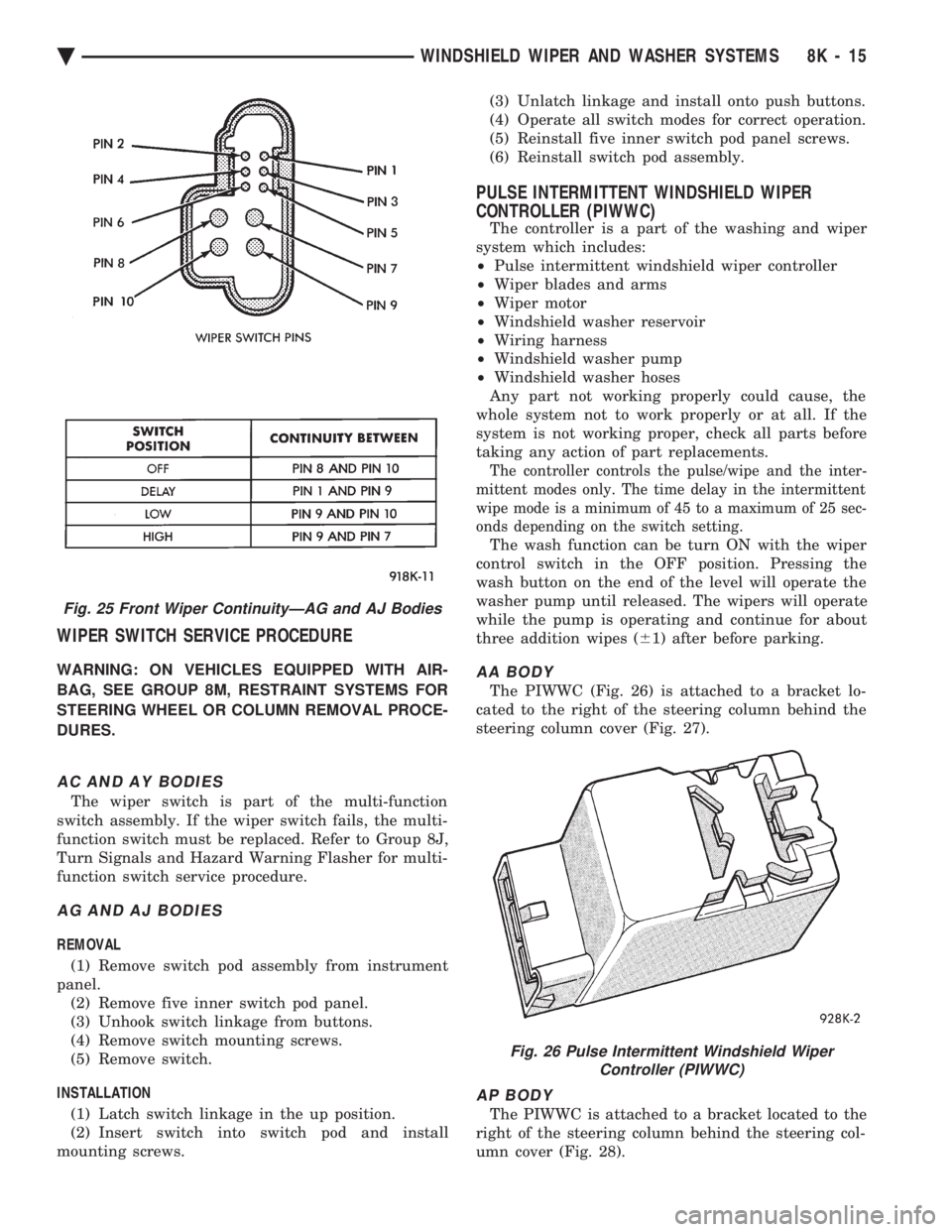
between the terminals of the switch, as indicated in
the following continuity chart (Fig. 25).
Fig. 23 Standard 2-Speed Wiper Switch Test
Fig. 24 Multi-Function Switch Connector and Intermittent Wipe Continuity
8K - 14 WINDSHIELD WIPER AND WASHER SYSTEMS Ä
Page 635 of 2438
WIPER SWITCH SERVICE PROCEDURE
WARNING: ON VEHICLES EQUIPPED WITH AIR-
BAG, SEE GROUP 8M, RESTRAINT SYSTEMS FOR
STEERING WHEEL OR COLUMN REMOVAL PROCE-
DURES.
AC AND AY BODIES
The wiper switch is part of the multi-function
switch assembly. If the wiper switch fails, the multi-
function switch must be replaced. Refer to Group 8J,
Turn Signals and Hazard Warning Flasher for multi-
function switch service procedure.
AG AND AJ BODIES
REMOVAL
(1) Remove switch pod assembly from instrument
panel. (2) Remove five inner switch pod panel.
(3) Unhook switch linkage from buttons.
(4) Remove switch mounting screws.
(5) Remove switch.
INSTALLATION (1) Latch switch linkage in the up position.
(2) Insert switch into switch pod and install
mounting screws. (3) Unlatch linkage and install onto push buttons.
(4) Operate all switch modes for correct operation.
(5) Reinstall five inner switch pod panel screws.
(6) Reinstall switch pod assembly.
PULSE INTERMITTENT WINDSHIELD WIPER
CONTROLLER (PIWWC)
The controller is a part of the washing and wiper
system which includes:
² Pulse intermittent windshield wiper controller
² Wiper blades and arms
² Wiper motor
² Windshield washer reservoir
² Wiring harness
² Windshield washer pump
² Windshield washer hoses
Any part not working properly could cause, the
whole system not to work properly or at all. If the
system is not working proper, check all parts before
taking any action of part replacements.
The controller controls the pulse/wipe and the inter-
mittent modes only. The time delay in the intermittent
wipe mode is a minimum of 45 to a maximum of 25 sec-
onds depending on the switch setting.
The wash function can be turn ON with the wiper
control switch in the OFF position. Pressing the
wash button on the end of the level will operate the
washer pump until released. The wipers will operate
while the pump is operating and continue for about
three addition wipes ( 61) after before parking.
AA BODY
The PIWWC (Fig. 26) is attached to a bracket lo-
cated to the right of the steering column behind the
steering column cover (Fig. 27).
AP BODY
The PIWWC is attached to a bracket located to the
right of the steering column behind the steering col-
umn cover (Fig. 28).
Fig. 25 Front Wiper ContinuityÐAG and AJ Bodies
Fig. 26 Pulse Intermittent Windshield Wiper Controller (PIWWC)
Ä WINDSHIELD WIPER AND WASHER SYSTEMS 8K - 15
Page 637 of 2438
WINDSHIELD WASHERS INDEX
page page
General Information ....................... 17
Washer Nozzle .......................... 19 Washer Reservoir Pump
................... 18
Washer Reservoirs ....................... 17
GENERAL INFORMATION
All models are equipped with electric operated
windshield washer pumps. The wash function can be accessed in the OFF po-
sition of the wiper control switch. Holding the wash
button depressed when the switch is in the OFF po-
sition will operate the wipers and washer motor
pump continuously until the washer button is re-
leased. Releasing the button will stop the washer
pump but the wipers will complete the current wipe
cycle. Then followed by an average of two more wipe
cycles ( 61) before the wipers park and the module
turns off. Whenever a windshield washer malfunction occurs,
first verify that the windshield washer wire harness
is properly connected to all connectors before starting
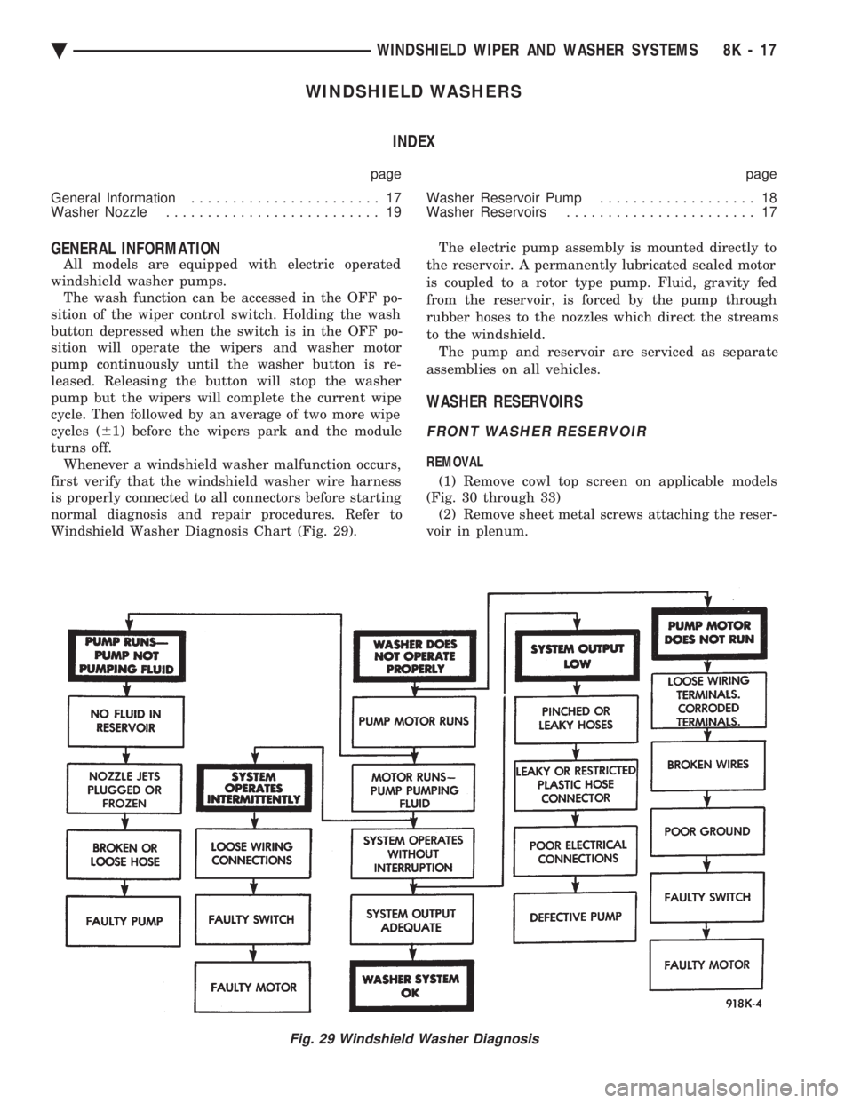
normal diagnosis and repair procedures. Refer to
Windshield Washer Diagnosis Chart (Fig. 29). The electric pump assembly is mounted directly to
the reservoir. A permanently lubricated sealed motor
is coupled to a rotor type pump. Fluid, gravity fed
from the reservoir, is forced by the pump through
rubber hoses to the nozzles which direct the streams
to the windshield. The pump and reservoir are serviced as separate
assemblies on all vehicles.
WASHER RESERVOIRS
FRONT WASHER RESERVOIR
REMOVAL
(1) Remove cowl top screen on applicable models
(Fig. 30 through 33) (2) Remove sheet metal screws attaching the reser-
voir in plenum.
Fig. 29 Windshield Washer Diagnosis
Ä WINDSHIELD WIPER AND WASHER SYSTEMS 8K - 17