1993 CHEVROLET DYNASTY service
[x] Cancel search: servicePage 1760 of 2438
FUEL TANK PRESSURE RELIEF AND ROLL-OVER
VALVE
REMOVAL
WARNING: RELEASE FUEL SYSTEM PRESSURE BE-
FORE SERVICING FUEL SYSTEM COMPONENTS.
WHEN SERVICING FLEXIBLE FUEL VEHICLES,
WEAR METHANOL RESISTANT GLOVES AND EYE
PROTECTION AND AVOID BREATHING FUMES. DO
NOT ALLOW METHANOL/GASOLINE MIXTURES TO
CONTACT SKIN. SERVICE VEHICLES IN WELL VEN-
TILATED AREAS AND AVOID IGNITION SOURCES.
NEVER SMOKE WHILE SERVICING THE VEHICLE.
(1) Remove fuel tank. Refer to Fuel Tank Removal in
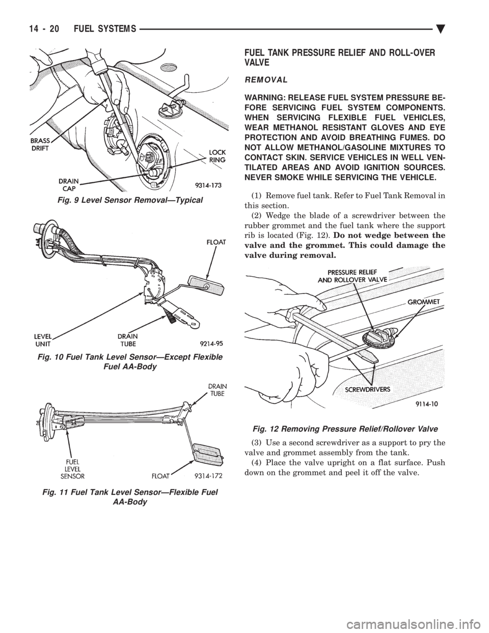
this section. (2) Wedge the blade of a screwdriver between the
rubber grommet and the fuel tank where the support
rib is located (Fig. 12). Do not wedge between the
valve and the grommet. This could damage the
valve during removal.
(3) Use a second screwdriver as a support to pry the
valve and grommet assembly from the tank. (4) Place the valve upright on a flat surface. Push
down on the grommet and peel it off the valve.
Fig. 9 Level Sensor RemovalÐTypical
Fig. 10 Fuel Tank Level SensorÐExcept Flexible Fuel AA-Body
Fig. 11 Fuel Tank Level SensorÐFlexible Fuel AA-Body
Fig. 12 Removing Pressure Relief/Rollover Valve
14 - 20 FUEL SYSTEMS Ä
Page 1770 of 2438
The PCM removes the ground to the solenoid when
the engine reaches a specified temperature and the
time delay interval has occurred. When the solenoid is
de-energized, vacuum flows to the canister purge
valve. Vapors are purged from the canister and flow to
the throttle body. The purge solenoid is also energized during certain
idle conditions to update the fuel delivery calibration.
MALFUNCTION INDICATOR LAMP (CHECK
ENGINE)ÐPCM OUTPUT
The Malfunction Indicator lamp (instrument panel
Check Engine lamp) comes on each time the ignition
key is turned ON and stays on for 3 seconds as a bulb
test. The malfunction indicator lamp warns the opera-
tor that the PCM has entered a Limp-in mode. During
Limp-in-Mode, the PCM attempts to keep the system
operational. The malfunction indicator lamp signals
the need for immediate service. In limp-in mode, the
PCM compensates for the failure of certain components
that send incorrect signals. The PCM substitutes for
the incorrect signals with inputs from other sensors. Signals that can trigger the Malfunction Indi-
cator Lamp.
² Coolant Temperature Sensor
² Manifold Absolute Pressure Sensor
² Throttle Position Sensor
² Battery Voltage Input
² An Emissions Related System
² Charging system
The malfunction indicator lamp can also be used to
display diagnostic trouble codes. Cycle the ignition
switch on, off, on, off, on, within five seconds and any
diagnostic trouble codes stored in the PCM will be
displayed. Refer to the 2.2L/2.5L Single Point Fuel
InjectionÐOn-Board Diagnostics section in this group.
DATA LINK CONNECTORÐPCM OUTPUT
The data link connector provides the technician with
the means to connect the DRBII scan tool to diagnosis
the vehicle.
ELECTRIC ELECTRONIC GAS
RECIRCULATIONÐPCM OUTPUT
The electronic exhaust gas recirculation transducer
(EET) is a back pressure transducer/electric vacuum
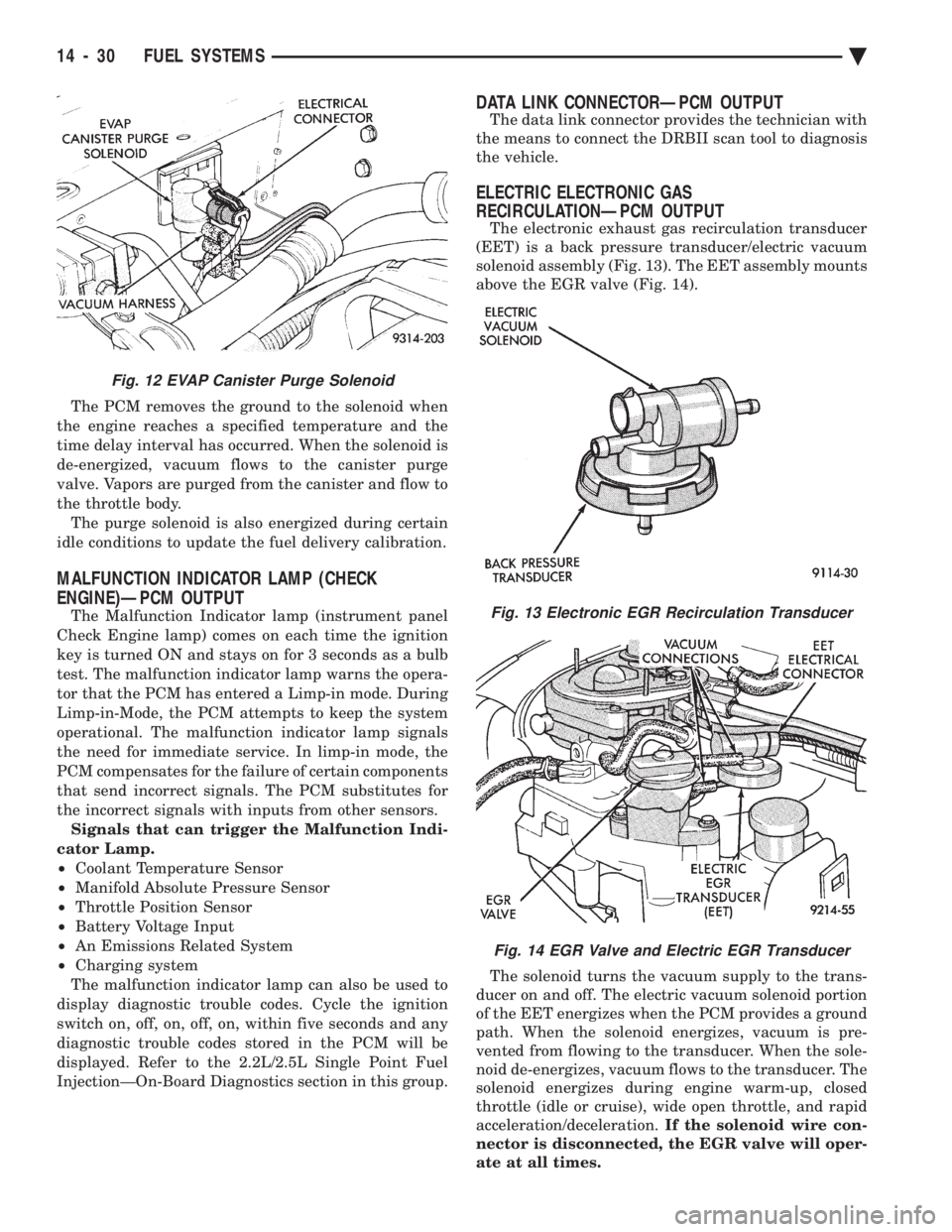
solenoid assembly (Fig. 13). The EET assembly mounts
above the EGR valve (Fig. 14).
The solenoid turns the vacuum supply to the trans-
ducer on and off. The electric vacuum solenoid portion
of the EET energizes when the PCM provides a ground
path. When the solenoid energizes, vacuum is pre-
vented from flowing to the transducer. When the sole-
noid de-energizes, vacuum flows to the transducer. The
solenoid energizes during engine warm-up, closed
throttle (idle or cruise), wide open throttle, and rapid
acceleration/deceleration. If the solenoid wire con-
nector is disconnected, the EGR valve will oper-
ate at all times.
Fig. 12 EVAP Canister Purge Solenoid
Fig. 13 Electronic EGR Recirculation Transducer
Fig. 14 EGR Valve and Electric EGR Transducer
14 - 30 FUEL SYSTEMS Ä
Page 1788 of 2438
2.2L/2.5L SINGLE POINT FUEL INJECTIONÐSERVICE PROCEDURES INDEX
page page
Canister Purge Solenoid ................... 53
Electric Exhaust Gas Recirculation Transducer (EET) Service ............................... 53
Fuel Fitting ............................. 50
Fuel Injector ............................ 51
Fuel Lines and Hoses ..................... 48
Fuel Pressure Regulator ................... 51 Fuel System Pressure Release Procedure
...... 48
Heated Oxygen Sensor (O
2Sensor) .......... 54
Idle Air Control Motor ..................... 53
Manifold Absolute Pressure Sensor ........... 53
PCM Service ............................ 54
Throttle Body ............................ 48
Throttle Position Sensor ................... 52
FUEL LINES AND HOSES
Perform the Fuel System Pressure Relief Procedure
before servicing the fuel system. The procedure must
be done to bleed fuel pressure from the system before
removing clamps or hoses. Use care when removing fuel hoses to prevent dam-
age to hose or hose nipple. Always use new hose
clamps, of the correct type, during reassembly. Tighten
hose clamps to 1 N Im (10 in. lbs.) torque. Do not use
aviation style clamps on this system or hose
damage may result.
FUEL SYSTEM PRESSURE RELEASE PROCEDURE
CAUTION: Before servicing the fuel pump, fuel lines,
fuel filter, throttle body, or fuel injector, release fuel
system pressure.
(1) Loosen fuel filler cap to release fuel tank pres-
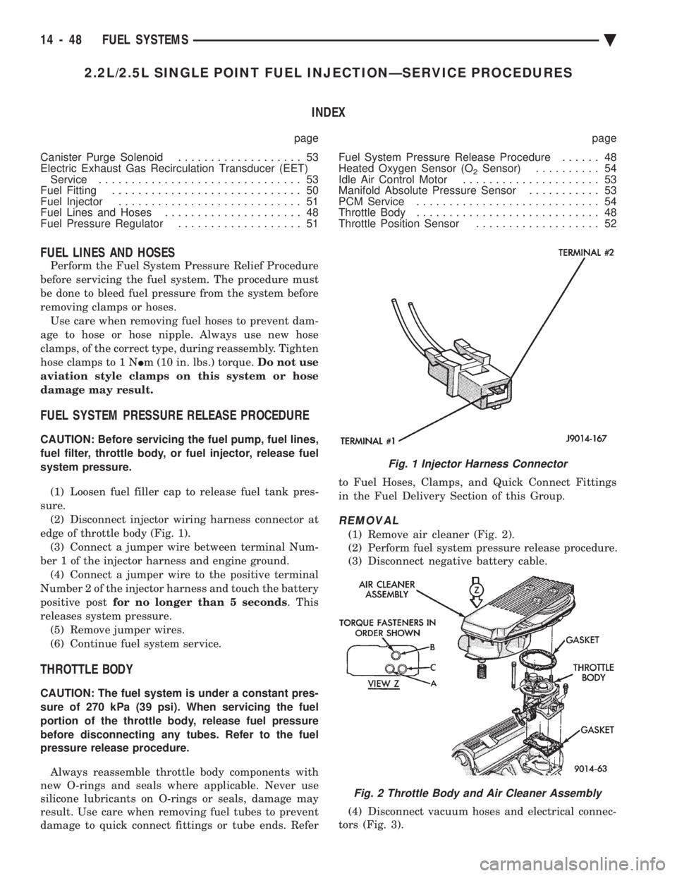
sure. (2) Disconnect injector wiring harness connector at
edge of throttle body (Fig. 1). (3) Connect a jumper wire between terminal Num-
ber 1 of the injector harness and engine ground. (4) Connect a jumper wire to the positive terminal
Number 2 of the injector harness and touch the battery
positive post for no longer than 5 seconds . This
releases system pressure. (5) Remove jumper wires.
(6) Continue fuel system service.
THROTTLE BODY
CAUTION: The fuel system is under a constant pres-
sure of 270 kPa (39 psi). When servicing the fuel
portion of the throttle body, release fuel pressure
before disconnecting any tubes. Refer to the fuel
pressure release procedure.
Always reassemble throttle body components with
new O-rings and seals where applicable. Never use
silicone lubricants on O-rings or seals, damage may
result. Use care when removing fuel tubes to prevent
damage to quick connect fittings or tube ends. Refer to Fuel Hoses, Clamps, and Quick Connect Fittings
in the Fuel Delivery Section of this Group.
REMOVAL
(1) Remove air cleaner (Fig. 2).
(2) Perform fuel system pressure release procedure.
(3) Disconnect negative battery cable.
(4) Disconnect vacuum hoses and electrical connec-
tors (Fig. 3).
Fig. 1 Injector Harness Connector
Fig. 2 Throttle Body and Air Cleaner Assembly
14 - 48 FUEL SYSTEMS Ä
Page 1793 of 2438
(3) Install air cleaner.
(4) Connect negative cable to battery.
IDLE AIR CONTROL MOTOR
The idle air control motor is mounted on the throt-
tle body (Fig. 14).
REMOVAL
(1) Remove air cleaner.
(2) Disconnect negative cable from battery.
(3) Disconnect idle air control motor connector.
(4) Remove idle air control motor mounting screws
(Torx head screws, 25 mm long). (5) Remove idle air control motor from throttle
body housing. Ensure O-ring was removed with idle
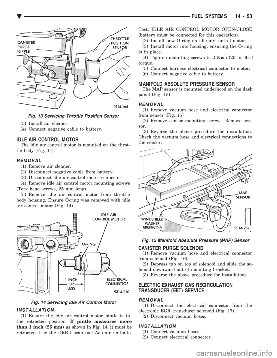
air control motor (Fig. 14).
INSTALLATION
(1) Ensure the idle air control motor pintle is in
the retracted position. If pintle measures more
than 1 inch (25 mm) as shown in Fig. 14, it must be
retracted. Use the DRBII scan tool Actuate Outputs Test, IDLE AIR CONTROL MOTOR OPEN/CLOSE
(battery must be connected for this operation). (2) Install new O-ring on idle air control motor.
(3) Install motor into housing, ensuring the O-ring
is in place. (4) Tighten mounting screws to 2 N Im (20 in. lbs.)
torque. (5) Connect harness electrical connector to motor.
(6) Connect negative cable to battery.
MANIFOLD ABSOLUTE PRESSURE SENSOR
The MAP sensor is mounted underhood on the dash
panel (Fig. 15)
REMOVAL
(1) Remove vacuum hose and electrical connector
from sensor (Fig. 15). (2) Remove sensor mounting screws. Remove sen-
sor. (3) Reverse the above procedure for installation.
Check the vacuum hose and electrical connections to
the sensor.
CANISTER PURGE SOLENOID
(1) Remove vacuum hose and electrical connector
from solenoid (Fig. 16). (2) Depress tab on top of solenoid and slide the so-
lenoid downward out of mounting bracket. (3) Reverse the above procedure for installation.
ELECTRIC EXHAUST GAS RECIRCULATION
TRANSDUCER (EET) SERVICE
REMOVAL
(1) Disconnect the electrical connector from the
electronic EGR transducer solenoid (Fig. 17). (2) Disconnect vacuum hoses.
INSTALLATION
(1) Connect vacuum hoses.
(2) Connect electrical connector.
Fig. 15 Manifold Absolute Pressure (MAP) Sensor
Fig. 13 Servicing Throttle Position Sensor
Fig. 14 Servicing Idle Air Control Motor
Ä FUEL SYSTEMS 14 - 53
Page 1794 of 2438
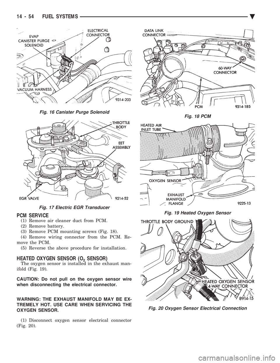
PCM SERVICE
(1) Remove air cleaner duct from PCM.
(2) Remove battery.
(3) Remove PCM mounting screws (Fig. 18).
(4) Remove wiring connector from the PCM. Re-
move the PCM. (5) Reverse the above procedure for installation.
HEATED OXYGEN SENSOR (O2SENSOR)
The oxygen sensor is installed in the exhaust man-
ifold (Fig. 19).
CAUTION: Do not pull on the oxygen sensor wire
when disconnecting the electrical connector.
WARNING: THE EXHAUST MANIFOLD MAY BE EX-
TREMELY HOT. USE CARE WHEN SERVICING THE
OXYGEN SENSOR.
(1) Disconnect oxygen sensor electrical connector
(Fig. 20).
Fig. 18 PCM
Fig. 19 Heated Oxygen Sensor
Fig. 20 Oxygen Sensor Electrical Connection
Fig. 16 Canister Purge Solenoid
Fig. 17 Electric EGR Transducer
14 - 54 FUEL SYSTEMS Ä
Page 1802 of 2438
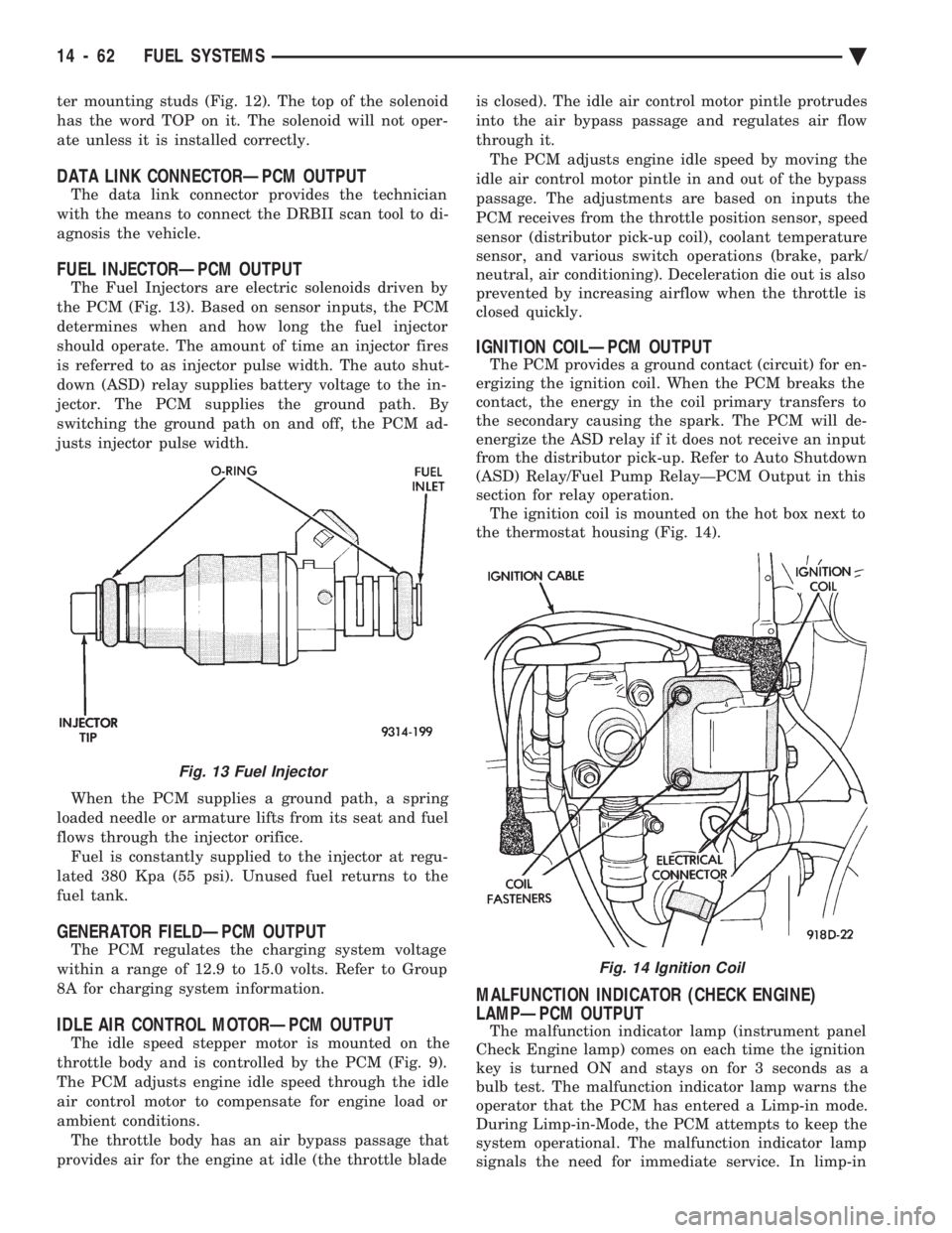
ter mounting studs (Fig. 12). The top of the solenoid
has the word TOP on it. The solenoid will not oper-
ate unless it is installed correctly.
DATA LINK CONNECTORÐPCM OUTPUT
The data link connector provides the technician
with the means to connect the DRBII scan tool to di-
agnosis the vehicle.
FUEL INJECTORÐPCM OUTPUT
The Fuel Injectors are electric solenoids driven by
the PCM (Fig. 13). Based on sensor inputs, the PCM
determines when and how long the fuel injector
should operate. The amount of time an injector fires
is referred to as injector pulse width. The auto shut-
down (ASD) relay supplies battery voltage to the in-
jector. The PCM supplies the ground path. By
switching the ground path on and off, the PCM ad-
justs injector pulse width.
When the PCM supplies a ground path, a spring
loaded needle or armature lifts from its seat and fuel
flows through the injector orifice. Fuel is constantly supplied to the injector at regu-
lated 380 Kpa (55 psi). Unused fuel returns to the
fuel tank.
GENERATOR FIELDÐPCM OUTPUT
The PCM regulates the charging system voltage
within a range of 12.9 to 15.0 volts. Refer to Group
8A for charging system information.
IDLE AIR CONTROL MOTORÐPCM OUTPUT
The idle speed stepper motor is mounted on the
throttle body and is controlled by the PCM (Fig. 9).
The PCM adjusts engine idle speed through the idle
air control motor to compensate for engine load or
ambient conditions. The throttle body has an air bypass passage that
provides air for the engine at idle (the throttle blade is closed). The idle air control motor pintle protrudes
into the air bypass passage and regulates air flow
through it. The PCM adjusts engine idle speed by moving the
idle air control motor pintle in and out of the bypass
passage. The adjustments are based on inputs the
PCM receives from the throttle position sensor, speed
sensor (distributor pick-up coil), coolant temperature
sensor, and various switch operations (brake, park/
neutral, air conditioning). Deceleration die out is also
prevented by increasing airflow when the throttle is
closed quickly.
IGNITION COILÐPCM OUTPUT
The PCM provides a ground contact (circuit) for en-
ergizing the ignition coil. When the PCM breaks the
contact, the energy in the coil primary transfers to
the secondary causing the spark. The PCM will de-
energize the ASD relay if it does not receive an input
from the distributor pick-up. Refer to Auto Shutdown
(ASD) Relay/Fuel Pump RelayÐPCM Output in this
section for relay operation. The ignition coil is mounted on the hot box next to
the thermostat housing (Fig. 14).
MALFUNCTION INDICATOR (CHECK ENGINE)
LAMPÐPCM OUTPUT
The malfunction indicator lamp (instrument panel
Check Engine lamp) comes on each time the ignition
key is turned ON and stays on for 3 seconds as a
bulb test. The malfunction indicator lamp warns the
operator that the PCM has entered a Limp-in mode.
During Limp-in-Mode, the PCM attempts to keep the
system operational. The malfunction indicator lamp
signals the need for immediate service. In limp-in
Fig. 13 Fuel Injector
Fig. 14 Ignition Coil
14 - 62 FUEL SYSTEMS Ä
Page 1817 of 2438
2.5L FLEXIBLE FUEL MULTI-PORT FUEL INJECTIONÐSERVICE PROCEDURES INDEX
page page
Fuel Injector ............................. 80
Fuel Injector Rail Assembly ................. 79
Fuel Pressure Regulator .................... 81
Fuel System Pressure Release Procedure ...... 78
General Information ....................... 77
Heated Oxygen Sensor (O
2Sensor) ........... 82
Identifying Flexible Fuel Components .......... 77
Idle Air Control Motor ...................... 78 Manifold Absolute Pressure (MAP) Sensor
Service ............................... 82
Methanol Concentration Sensor .............. 82
PCM Service ............................ 82
Service Precautions for Flexible Fuel Vehicles .... 77
Throttle Body ............................ 77
Throttle Body Removal ..................... 79
Throttle Position Sensor (TPS) ............... 78
GENERAL INFORMATION
In this model year Chrysler began producing AA-
Body vehicles designed to operate on a mixture of
gasoline and methanol. These automobiles are referred
to as Flexible Fuel vehicles. Fuel system components
designed for use in flexible fuel vehicles are referred to
as Methanol Compatible. Flexible fuel vehicles can operate on a mixture of up
to 85 percent methanol, 15 percent unleaded gasoline.
These vehicles also operate on mixtures containing a
lower percentage of methanol or just pure unleaded
gasoline.
SERVICE PRECAUTIONS FOR FLEXIBLE FUEL
VEHICLES
Methanol is more toxic than gasoline. Always release
fuel system pressure before servicing fuel system com-
ponents and wear methanol resistant gloves and eye
protection. Avoid breathing methanol vapors or ingesting
methanol. Headaches, dizziness and even unconscious-
ness could result from breathing these vapors. Serious
injury, blindness and even death could result from
ingesting methanol. Methanol vapors are extremely flammable and can
travel along the ground. Service vehicles in well ven-
tilated areas and avoid ignition sources. Never smoke
while servicing the vehicle. Do not allow methanol to contact skin. Prolonged
contact with methanol can cause dry skin or an allergic
skin reaction. Also, prolonged contact could result in
absorption through the skin.
IDENTIFYING FLEXIBLE FUEL COMPONENTS
Flexible Fuel vehicles have unique methanol compat-
ible fuel system components. Chrysler identifies methanol
compatible components that could be physically inter-
changed with gasoline only parts by coloring them green
or applying a green label or tag to them. Even though
they may appear physically identical, components
for gasoline only AA-body vehicles must not be used
on flexible fuel vehicles.
FLEXIBLE FUEL COMPONENTS
The fuel system of flexible fuel AA-body vehicles have
the following unique methanol compatible components.
² Duty cycle EVAP purge solenoid
² EVAP canister
² Fuel pump module
² Fuel level sensor
² Fuel gauge (gauge cluster).
² Fuel tank
² Fuel pressure regulator (including O-rings)
² Fuel rail
² Fuel injectors (including O-rings)
² Fuel tubes
² Fuel filter
² Fuel filler cap
² Fuel filler tube
² Methanol concentration sensor
² Pressure relief/rollover valve
² PCV Valve
² All fuel system and emission system hoses and tubes
THROTTLE BODY
WARNING: THROTTLE BODIES DESIGNED FOR
GASOLINE ONLY VEHICLES CANNOT BE USED ON
FLEXIBLE FUEL AA-BODY VEHICLES. WHEN RE-
PLACING THE THROTTLE BODY OF A FLEXIBLE
FUEL VEHICLE, ONLY USE AN ORIGINAL EQUIP-
MENT REPLACEMENT.
When servicing throttle body components, always
reassemble components with new O-rings and seals
where applicable. Never use lubricants on O-rings or
seals, damage may result. If assembly of component is
difficult, use water to aid assembly. Use care when
removing hoses to prevent damage to hose or hose
nipple.
Ä FUEL SYSTEMS 14 - 77
Page 1818 of 2438
FUEL SYSTEM PRESSURE RELEASE PROCEDURE
WARNING: RELEASE FUEL SYSTEM PRESSURE
BEFORE SERVICING FUEL SYSTEM COMPONENTS.
WHEN SERVICING FLEXIBLE FUEL VEHICLES,
WEAR METHANOL RESISTANT GLOVES AND EYE
PROTECTION AND AVOID BREATHING FUMES. DO
NOT ALLOW METHANOL/GASOLINE MIXTURES TO
CONTACT SKIN. SERVICE VEHICLES IN WELL VEN-
TILATED AREAS AND AVOID IGNITION SOURCES.
NEVER SMOKE WHILE SERVICING THE VEHICLE.
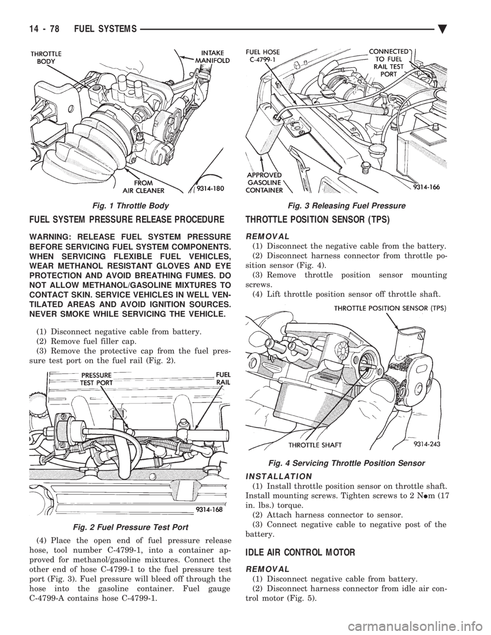
(1) Disconnect negative cable from battery.
(2) Remove fuel filler cap.
(3) Remove the protective cap from the fuel pres-
sure test port on the fuel rail (Fig. 2).
(4) Place the open end of fuel pressure release
hose, tool number C-4799-1, into a container ap-
proved for methanol/gasoline mixtures. Connect the
other end of hose C-4799-1 to the fuel pressure test
port (Fig. 3). Fuel pressure will bleed off through the
hose into the gasoline container. Fuel gauge
C-4799-A contains hose C-4799-1.
THROTTLE POSITION SENSOR (TPS)
REMOVAL
(1) Disconnect the negative cable from the battery.
(2) Disconnect harness connector from throttle po-
sition sensor (Fig. 4). (3) Remove throttle position sensor mounting
screws. (4) Lift throttle position sensor off throttle shaft.
INSTALLATION
(1) Install throttle position sensor on throttle shaft.
Install mounting screws. Tighten screws to 2 N Im (17
in. lbs.) torque. (2) Attach harness connector to sensor.
(3) Connect negative cable to negative post of the
battery.
IDLE AIR CONTROL MOTOR
REMOVAL
(1) Disconnect negative cable from battery.
(2) Disconnect harness connector from idle air con-
trol motor (Fig. 5).
Fig. 1 Throttle Body
Fig. 2 Fuel Pressure Test Port
Fig. 3 Releasing Fuel Pressure
Fig. 4 Servicing Throttle Position Sensor
14 - 78 FUEL SYSTEMS Ä