1993 CHEVROLET DYNASTY service
[x] Cancel search: servicePage 1819 of 2438
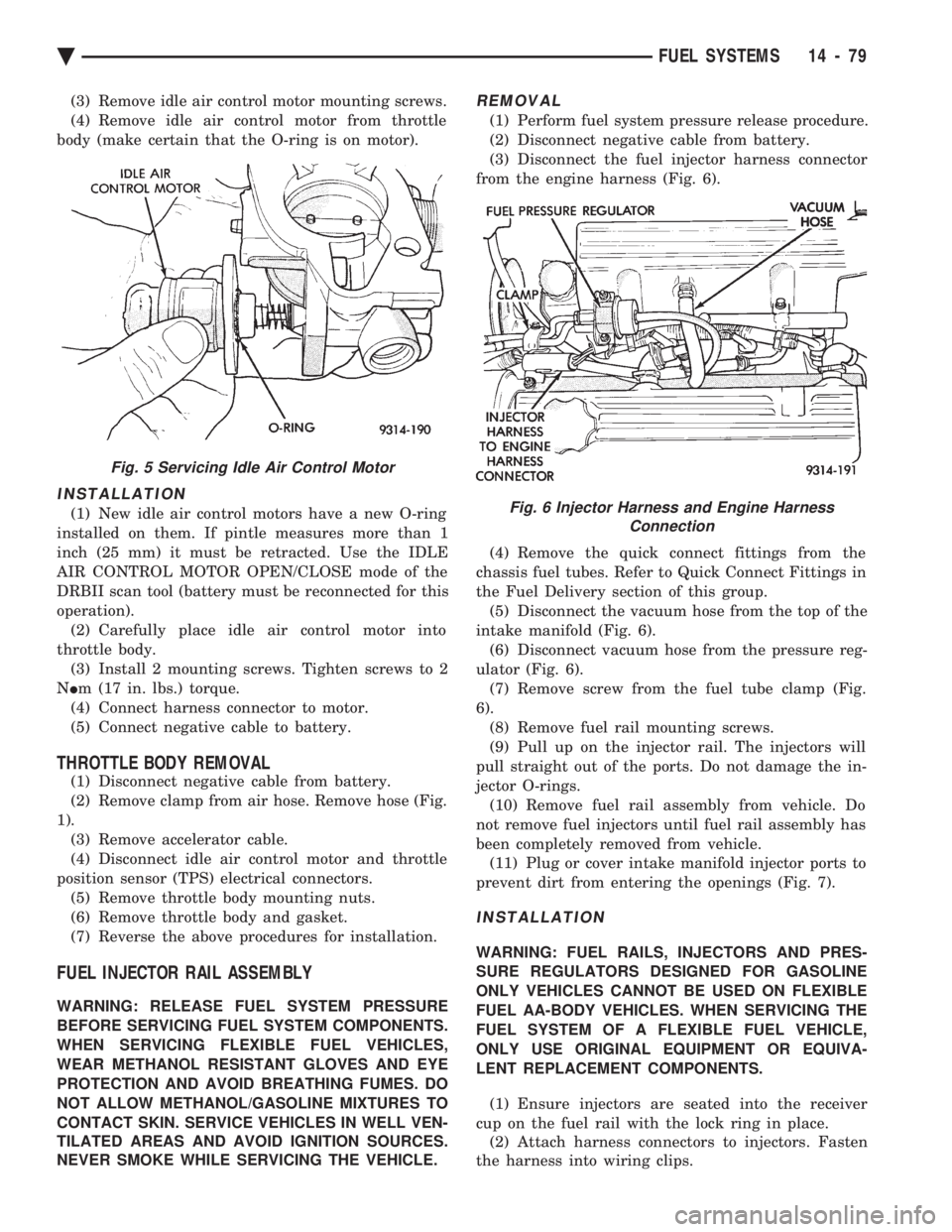
(3) Remove idle air control motor mounting screws.
(4) Remove idle air control motor from throttle
body (make certain that the O-ring is on motor).
INSTALLATION
(1) New idle air control motors have a new O-ring
installed on them. If pintle measures more than 1
inch (25 mm) it must be retracted. Use the IDLE
AIR CONTROL MOTOR OPEN/CLOSE mode of the
DRBII scan tool (battery must be reconnected for this
operation). (2) Carefully place idle air control motor into
throttle body. (3) Install 2 mounting screws. Tighten screws to 2
N Im (17 in. lbs.) torque.
(4) Connect harness connector to motor.
(5) Connect negative cable to battery.
THROTTLE BODY REMOVAL
(1) Disconnect negative cable from battery.
(2) Remove clamp from air hose. Remove hose (Fig.
1). (3) Remove accelerator cable.
(4) Disconnect idle air control motor and throttle
position sensor (TPS) electrical connectors. (5) Remove throttle body mounting nuts.
(6) Remove throttle body and gasket.
(7) Reverse the above procedures for installation.
FUEL INJECTOR RAIL ASSEMBLY
WARNING: RELEASE FUEL SYSTEM PRESSURE
BEFORE SERVICING FUEL SYSTEM COMPONENTS.
WHEN SERVICING FLEXIBLE FUEL VEHICLES,
WEAR METHANOL RESISTANT GLOVES AND EYE
PROTECTION AND AVOID BREATHING FUMES. DO
NOT ALLOW METHANOL/GASOLINE MIXTURES TO
CONTACT SKIN. SERVICE VEHICLES IN WELL VEN-
TILATED AREAS AND AVOID IGNITION SOURCES.
NEVER SMOKE WHILE SERVICING THE VEHICLE.
REMOVAL
(1) Perform fuel system pressure release procedure.
(2) Disconnect negative cable from battery.
(3) Disconnect the fuel injector harness connector
from the engine harness (Fig. 6).
(4) Remove the quick connect fittings from the
chassis fuel tubes. Refer to Quick Connect Fittings in
the Fuel Delivery section of this group. (5) Disconnect the vacuum hose from the top of the
intake manifold (Fig. 6). (6) Disconnect vacuum hose from the pressure reg-
ulator (Fig. 6). (7) Remove screw from the fuel tube clamp (Fig.
6). (8) Remove fuel rail mounting screws.
(9) Pull up on the injector rail. The injectors will
pull straight out of the ports. Do not damage the in-
jector O-rings. (10) Remove fuel rail assembly from vehicle. Do
not remove fuel injectors until fuel rail assembly has
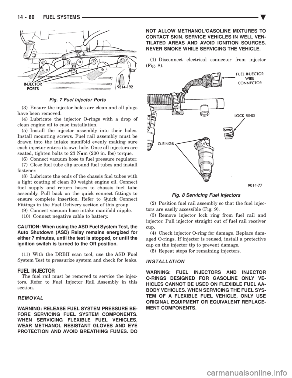
been completely removed from vehicle. (11) Plug or cover intake manifold injector ports to
prevent dirt from entering the openings (Fig. 7).
INSTALLATION
WARNING: FUEL RAILS, INJECTORS AND PRES-
SURE REGULATORS DESIGNED FOR GASOLINE
ONLY VEHICLES CANNOT BE USED ON FLEXIBLE
FUEL AA-BODY VEHICLES. WHEN SERVICING THE
FUEL SYSTEM OF A FLEXIBLE FUEL VEHICLE,
ONLY USE ORIGINAL EQUIPMENT OR EQUIVA-
LENT REPLACEMENT COMPONENTS.
(1) Ensure injectors are seated into the receiver
cup on the fuel rail with the lock ring in place. (2) Attach harness connectors to injectors. Fasten
the harness into wiring clips.
Fig. 5 Servicing Idle Air Control Motor
Fig. 6 Injector Harness and Engine Harness Connection
Ä FUEL SYSTEMS 14 - 79
Page 1820 of 2438
(3) Ensure the injector holes are clean and all plugs
have been removed. (4) Lubricate the injector O-rings with a drop of
clean engine oil to ease installation. (5) Install the injector assembly into their holes.
Install mounting screws. Fuel rail assembly must be
drawn into the intake manifold evenly making sure
each injector enters its own hole. Once all injectors are
seated, tighten bolts to 23 N Im (200 in. lbs) torque.
(6) Connect vacuum hose to fuel pressure regulator.
(7) Close fuel tube clip around fuel tubes and install
fastener. (8) Lubricate the ends of the chassis fuel tubes with
a light coating of clean 30 weight engine oil. Connect
fuel supply and return hoses to chassis fuel tube
assembly. Pull back on the quick connect fittings to
ensure complete insertion. Refer to Quick Connect
Fittings in the Fuel Delivery section of this group. (9) Connect vacuum hose intake manifold nipple.
(10) Connect negative cable to battery.
CAUTION: When using the ASD Fuel System Test, the
Auto Shutdown (ASD) Relay remains energized for
either 7 minutes, until the test is stopped, or until the
ignition switch is turned to the Off position.
(11) With the DRBII scan tool, use the ASD Fuel
System Test to pressurize system and check for leaks.
FUEL INJECTOR
The fuel rail must be removed to service the injec-
tors. Refer to Fuel Injector Rail Assembly in this
section.
REMOVAL
WARNING: RELEASE FUEL SYSTEM PRESSURE BE-
FORE SERVICING FUEL SYSTEM COMPONENTS.
WHEN SERVICING FLEXIBLE FUEL VEHICLES,
WEAR METHANOL RESISTANT GLOVES AND EYE
PROTECTION AND AVOID BREATHING FUMES. DO NOT ALLOW METHANOL/GASOLINE MIXTURES TO
CONTACT SKIN. SERVICE VEHICLES IN WELL VEN-
TILATED AREAS AND AVOID IGNITION SOURCES.
NEVER SMOKE WHILE SERVICING THE VEHICLE.
(1) Disconnect electrical connector from injector
(Fig. 8).
(2) Position fuel rail assembly so that the fuel injec-
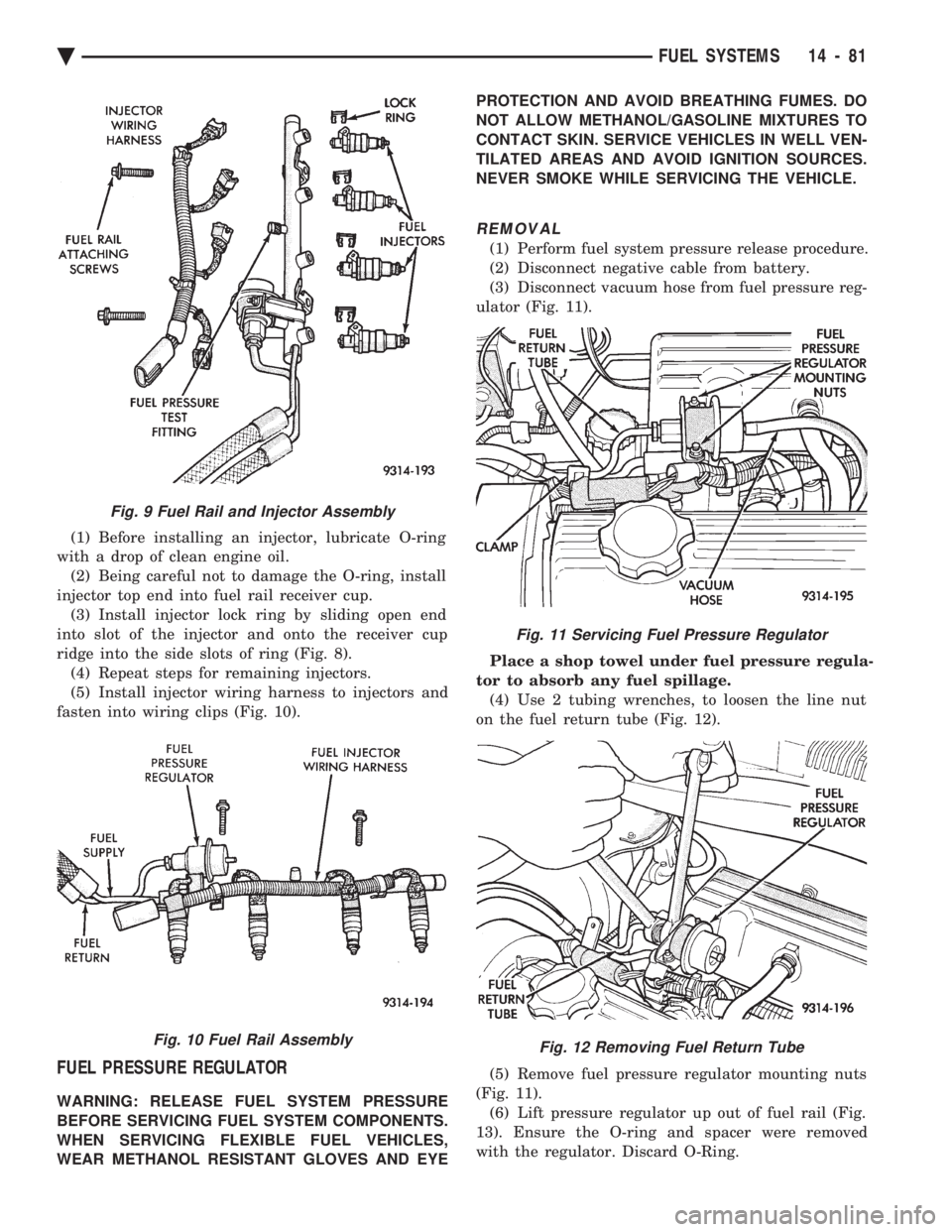
tors are easily accessible (Fig. 9). (3) Remove injector lock ring from fuel rail and
injector. Pull injector straight out of fuel rail receiver
cup. (4) Check injector O-ring for damage. Replace dam-
aged O-rings. If injector is reused, install a protective
cap on the injector tip to prevent damage. (5) Repeat steps for remaining injectors.
INSTALLATION
WARNING: FUEL INJECTORS AND INJECTOR
O-RINGS DESIGNED FOR GASOLINE ONLY VE-
HICLES CANNOT BE USED ON FLEXIBLE FUEL AA-
BODY VEHICLES. WHEN SERVICING THE FUEL SYS-
TEM OF A FLEXIBLE FUEL VEHICLE, ONLY USE
ORIGINAL EQUIPMENT OR EQUIVALENT REPLACE-
MENT COMPONENTS.
Fig. 7 Fuel Injector Ports
Fig. 8 Servicing Fuel Injectors
14 - 80 FUEL SYSTEMS Ä
Page 1821 of 2438
(1) Before installing an injector, lubricate O-ring
with a drop of clean engine oil. (2) Being careful not to damage the O-ring, install
injector top end into fuel rail receiver cup. (3) Install injector lock ring by sliding open end
into slot of the injector and onto the receiver cup
ridge into the side slots of ring (Fig. 8). (4) Repeat steps for remaining injectors.
(5) Install injector wiring harness to injectors and
fasten into wiring clips (Fig. 10).
FUEL PRESSURE REGULATOR
WARNING: RELEASE FUEL SYSTEM PRESSURE
BEFORE SERVICING FUEL SYSTEM COMPONENTS.
WHEN SERVICING FLEXIBLE FUEL VEHICLES,
WEAR METHANOL RESISTANT GLOVES AND EYE PROTECTION AND AVOID BREATHING FUMES. DO
NOT ALLOW METHANOL/GASOLINE MIXTURES TO
CONTACT SKIN. SERVICE VEHICLES IN WELL VEN-
TILATED AREAS AND AVOID IGNITION SOURCES.
NEVER SMOKE WHILE SERVICING THE VEHICLE.
REMOVAL
(1) Perform fuel system pressure release procedure.
(2) Disconnect negative cable from battery.
(3) Disconnect vacuum hose from fuel pressure reg-
ulator (Fig. 11).
Place a shop towel under fuel pressure regula-
tor to absorb any fuel spillage. (4) Use 2 tubing wrenches, to loosen the line nut
on the fuel return tube (Fig. 12).
(5) Remove fuel pressure regulator mounting nuts
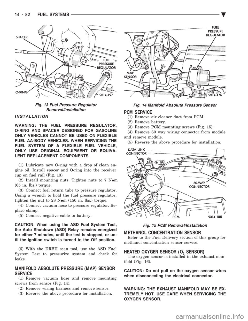
(Fig. 11). (6) Lift pressure regulator up out of fuel rail (Fig.
13). Ensure the O-ring and spacer were removed
with the regulator. Discard O-Ring.
Fig. 9 Fuel Rail and Injector Assembly
Fig. 10 Fuel Rail Assembly
Fig. 11 Servicing Fuel Pressure Regulator
Fig. 12 Removing Fuel Return Tube
Ä FUEL SYSTEMS 14 - 81
Page 1822 of 2438
INSTALLATION
WARNING: THE FUEL PRESSURE REGULATOR,
O-RING AND SPACER DESIGNED FOR GASOLINE
ONLY VEHICLES CANNOT BE USED ON FLEXIBLE
FUEL AA-BODY VEHICLES. WHEN SERVICING THE
FUEL SYSTEM OF A FLEXIBLE FUEL VEHICLE,
ONLY USE ORIGINAL EQUIPMENT OR EQUIVA-
LENT REPLACEMENT COMPONENTS.
(1) Lubricate new O-ring with a drop of clean en-
gine oil. Install spacer and O-ring into the receiver
cup on fuel rail (Fig. 13). (2) Install mounting nuts. Tighten nuts to 7 N Im
(65 in. lbs.) torque. (3) Connect fuel return tube to pressure regulator.
Using a wrench to hold the fuel pressure regulator,
tighten the nut to 28 N Im (150 in. lbs.) torque.
(4) Connect vacuum hose to pressure regulator. Re-
place clamp. (5) Connect negative cable to battery.
CAUTION: When using the ASD Fuel System Test,
the Auto Shutdown (ASD) Relay remains energized
for either 7 minutes, until the test is stopped, or un-
til the ignition switch is turned to the Off position.
(6) With the DRBII scan tool, use the ASD Fuel
System Test to pressurize system and check for
leaks.
MANIFOLD ABSOLUTE PRESSURE (MAP) SENSOR
SERVICE
(1) Remove vacuum hose and remove mounting
screws from sensor (Fig. 14). (2) Remove wiring harness and remove sensor.
(3) Reverse the above procedure for installation.
PCM SERVICE
(1) Remove air cleaner duct from PCM.
(2) Remove battery.
(3) Remove PCM mounting screws (Fig. 15).
(4) Remove 60 way wiring connector from module
and remove module. (5) Reverse the above procedure for installation.
METHANOL CONCENTRATION SENSOR
Refer to the Fuel Delivery section of this group for
methanol concentration sensor service.
HEATED OXYGEN SENSOR (O2SENSOR)
The oxygen sensor is installed in the exhaust man-
ifold (Fig. 16).
CAUTION: Do not pull on the oxygen sensor wires
when disconnecting the electrical connector.
WARNING: THE EXHAUST MANIFOLD MAY BE EX-
TREMELY HOT. USE CARE WHEN SERVICING THE
OXYGEN SENSOR.
Fig. 13 Fuel Pressure Regulator Removal/InstallationFig. 14 Manifold Absolute Pressure Sensor
Fig. 15 PCM Removal/Installation
14 - 82 FUEL SYSTEMS Ä
Page 1826 of 2438
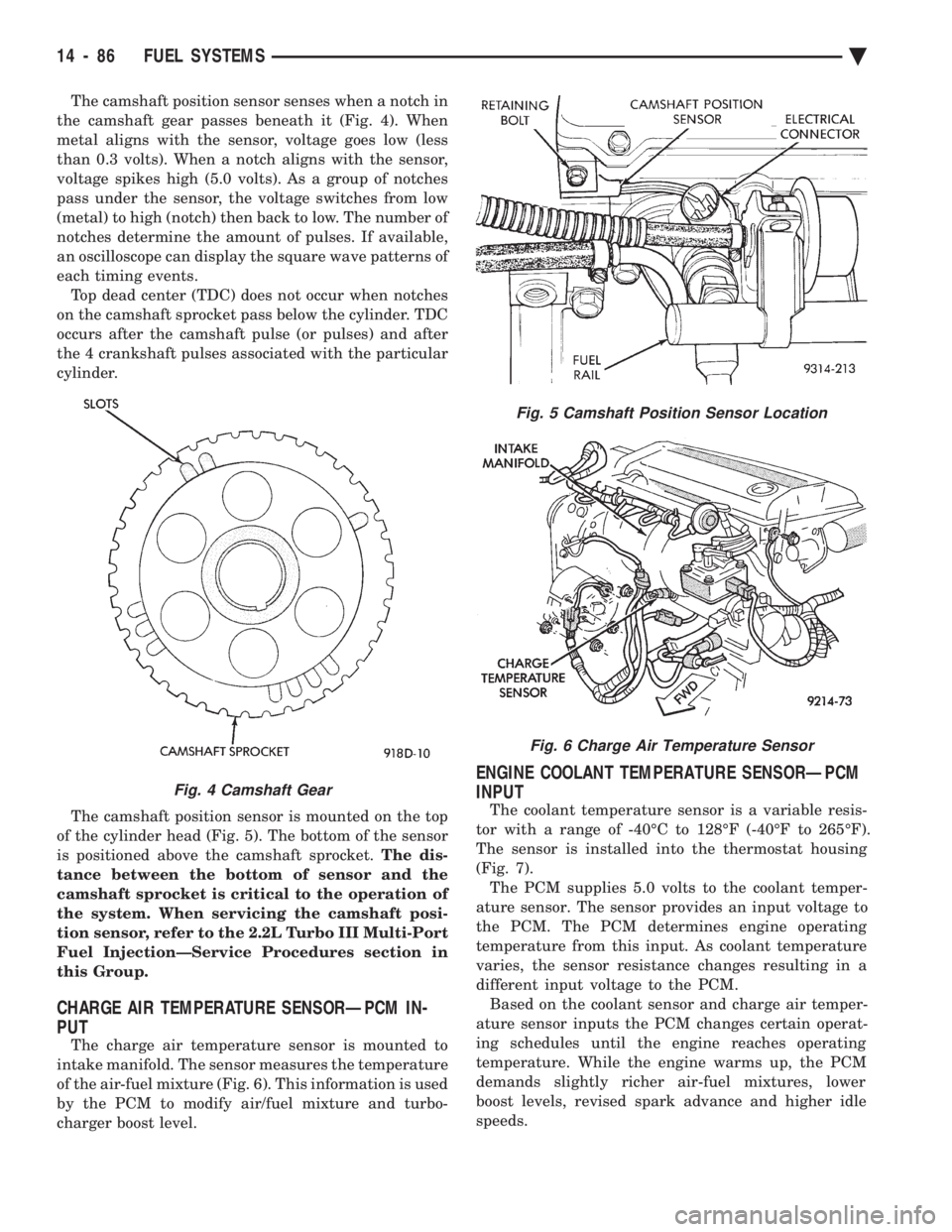
The camshaft position sensor senses when a notch in
the camshaft gear passes beneath it (Fig. 4). When
metal aligns with the sensor, voltage goes low (less
than 0.3 volts). When a notch aligns with the sensor,
voltage spikes high (5.0 volts). As a group of notches
pass under the sensor, the voltage switches from low
(metal) to high (notch) then back to low. The number of
notches determine the amount of pulses. If available,
an oscilloscope can display the square wave patterns of
each timing events. Top dead center (TDC) does not occur when notches
on the camshaft sprocket pass below the cylinder. TDC
occurs after the camshaft pulse (or pulses) and after
the 4 crankshaft pulses associated with the particular
cylinder.
The camshaft position sensor is mounted on the top
of the cylinder head (Fig. 5). The bottom of the sensor
is positioned above the camshaft sprocket. The dis-
tance between the bottom of sensor and the
camshaft sprocket is critical to the operation of
the system. When servicing the camshaft posi-
tion sensor, refer to the 2.2L Turbo III Multi-Port
Fuel InjectionÐService Procedures section in
this Group.
CHARGE AIR TEMPERATURE SENSORÐPCM IN-
PUT
The charge air temperature sensor is mounted to
intake manifold. The sensor measures the temperature
of the air-fuel mixture (Fig. 6). This information is used
by the PCM to modify air/fuel mixture and turbo-
charger boost level.
ENGINE COOLANT TEMPERATURE SENSORÐPCM
INPUT
The coolant temperature sensor is a variable resis-
tor with a range of -40ÉC to 128ÉF (-40ÉF to 265ÉF).
The sensor is installed into the thermostat housing
(Fig. 7). The PCM supplies 5.0 volts to the coolant temper-
ature sensor. The sensor provides an input voltage to
the PCM. The PCM determines engine operating
temperature from this input. As coolant temperature
varies, the sensor resistance changes resulting in a
different input voltage to the PCM. Based on the coolant sensor and charge air temper-
ature sensor inputs the PCM changes certain operat-
ing schedules until the engine reaches operating
temperature. While the engine warms up, the PCM
demands slightly richer air-fuel mixtures, lower
boost levels, revised spark advance and higher idle
speeds.
Fig. 5 Camshaft Position Sensor Location
Fig. 6 Charge Air Temperature Sensor
Fig. 4 Camshaft Gear
14 - 86 FUEL SYSTEMS Ä
Page 1827 of 2438
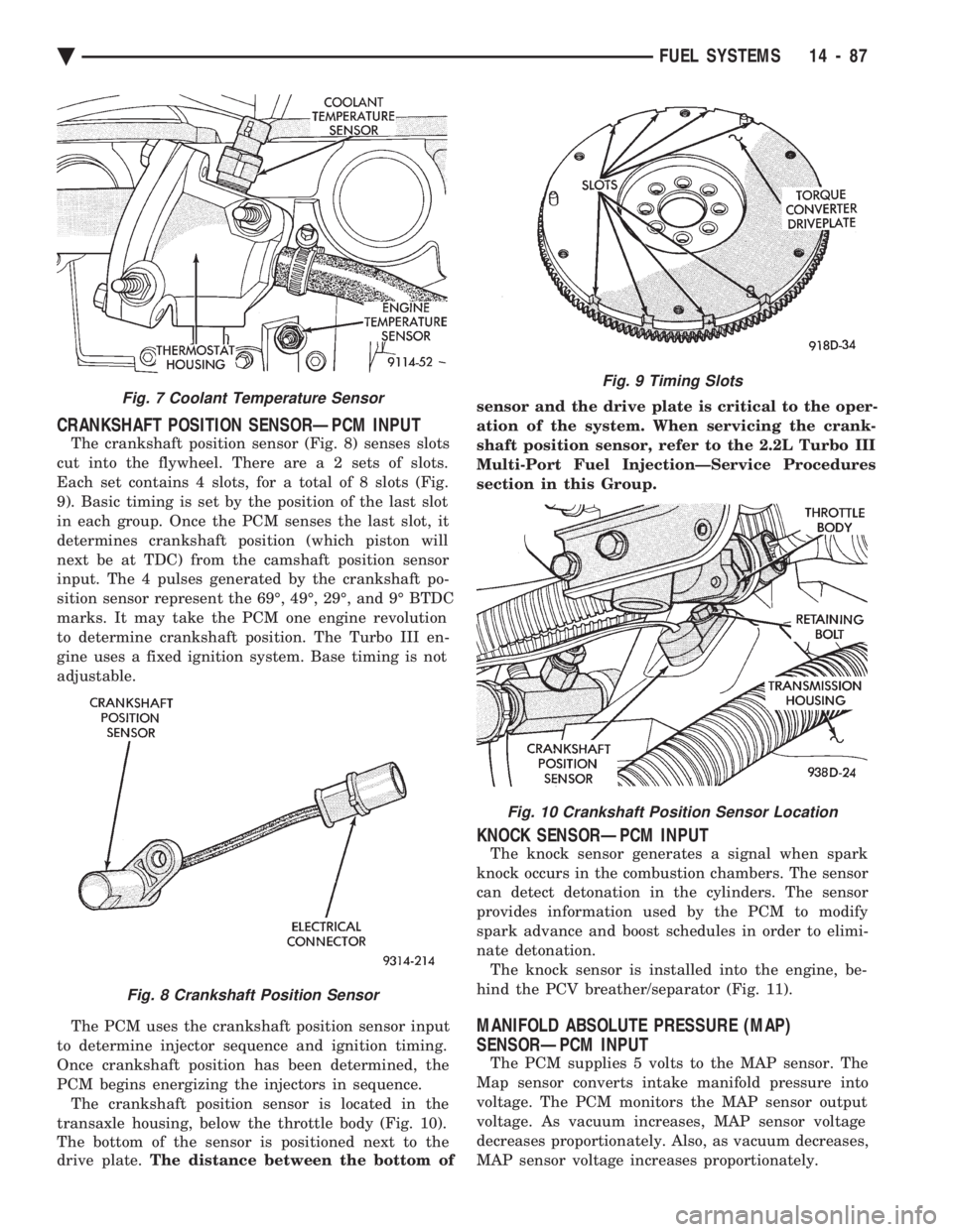
CRANKSHAFT POSITION SENSORÐPCM INPUT
The crankshaft position sensor (Fig. 8) senses slots
cut into the flywheel. There ar e a 2 sets of slots.
Each set contains 4 slots, for a total of 8 slots (Fig.
9). Basic timing is set by the position of the last slot
in each group. Once the PCM senses the last slot, it
determines crankshaft position (which piston will
next be at TDC) from the camshaft position sensor
input. The 4 pulses generated by the crankshaft po-
sition sensor represent the 69É, 49É, 29É, and 9É BTDC
marks. It may take the PCM one engine revolution
to determine crankshaft position. The Turbo III en-
gine uses a fixed ignition system. Base timing is not
adjustable.
The PCM uses the crankshaft position sensor input
to determine injector sequence and ignition timing.
Once crankshaft position has been determined, the
PCM begins energizing the injectors in sequence. The crankshaft position sensor is located in the
transaxle housing, below the throttle body (Fig. 10).
The bottom of the sensor is positioned next to the
drive plate. The distance between the bottom of sensor and the drive plate is critical to the oper-
ation of the system. When servicing the crank-
shaft position sensor, refer to the 2.2L Turbo III
Multi-Port Fuel InjectionÐService Procedures
section in this Group.
KNOCK SENSORÐPCM INPUT
The knock sensor generates a signal when spark
knock occurs in the combustion chambers. The sensor
can detect detonation in the cylinders. The sensor
provides information used by the PCM to modify
spark advance and boost schedules in order to elimi-
nate detonation. The knock sensor is installed into the engine, be-
hind the PCV breather/separator (Fig. 11).
MANIFOLD ABSOLUTE PRESSURE (MAP)
SENSORÐPCM INPUT
The PCM supplies 5 volts to the MAP sensor. The
Map sensor converts intake manifold pressure into
voltage. The PCM monitors the MAP sensor output
voltage. As vacuum increases, MAP sensor voltage
decreases proportionately. Also, as vacuum decreases,
MAP sensor voltage increases proportionately.
Fig. 7 Coolant Temperature Sensor
Fig. 8 Crankshaft Position Sensor
Fig. 9 Timing Slots
Fig. 10 Crankshaft Position Sensor Location
Ä FUEL SYSTEMS 14 - 87
Page 1830 of 2438
sition, the PCM monitors the crankshaft position and
camshaft position sensor signals to determine engine
speed and ignition timing (coil dwell). If the PCM
does not receive the crankshaft position sensor and
camshaft position sensor signals when the ignition
switch is in the Run position, it de-energizes both re-
lays. When the relays are de-energized, battery volt-
age is not supplied to the fuel injector, ignition coil,
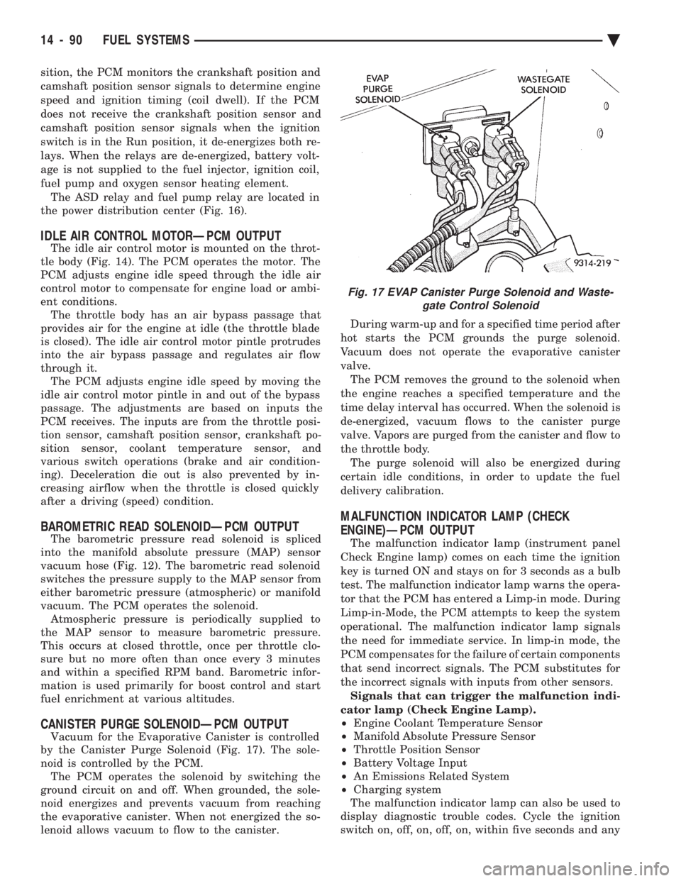
fuel pump and oxygen sensor heating element. The ASD relay and fuel pump relay are located in
the power distribution center (Fig. 16).
IDLE AIR CONTROL MOTORÐPCM OUTPUT
The idle air control motor is mounted on the throt-
tle body (Fig. 14). The PCM operates the motor. The
PCM adjusts engine idle speed through the idle air
control motor to compensate for engine load or ambi-
ent conditions. The throttle body has an air bypass passage that
provides air for the engine at idle (the throttle blade
is closed). The idle air control motor pintle protrudes
into the air bypass passage and regulates air flow
through it. The PCM adjusts engine idle speed by moving the
idle air control motor pintle in and out of the bypass
passage. The adjustments are based on inputs the
PCM receives. The inputs are from the throttle posi-
tion sensor, camshaft position sensor, crankshaft po-
sition sensor, coolant temperature sensor, and
various switch operations (brake and air condition-
ing). Deceleration die out is also prevented by in-
creasing airflow when the throttle is closed quickly
after a driving (speed) condition.
BAROMETRIC READ SOLENOIDÐPCM OUTPUT
The barometric pressure read solenoid is spliced
into the manifold absolute pressure (MAP) sensor
vacuum hose (Fig. 12). The barometric read solenoid
switches the pressure supply to the MAP sensor from
either barometric pressure (atmospheric) or manifold
vacuum. The PCM operates the solenoid. Atmospheric pressure is periodically supplied to
the MAP sensor to measure barometric pressure.
This occurs at closed throttle, once per throttle clo-
sure but no more often than once every 3 minutes
and within a specified RPM band. Barometric infor-
mation is used primarily for boost control and start
fuel enrichment at various altitudes.
CANISTER PURGE SOLENOIDÐPCM OUTPUT
Vacuum for the Evaporative Canister is controlled
by the Canister Purge Solenoid (Fig. 17). The sole-
noid is controlled by the PCM. The PCM operates the solenoid by switching the
ground circuit on and off. When grounded, the sole-
noid energizes and prevents vacuum from reaching
the evaporative canister. When not energized the so-
lenoid allows vacuum to flow to the canister. During warm-up and for a specified time period after
hot starts the PCM grounds the purge solenoid.
Vacuum does not operate the evaporative canister
valve. The PCM removes the ground to the solenoid when
the engine reaches a specified temperature and the
time delay interval has occurred. When the solenoid is
de-energized, vacuum flows to the canister purge
valve. Vapors are purged from the canister and flow to
the throttle body. The purge solenoid will also be energized during
certain idle conditions, in order to update the fuel
delivery calibration.
MALFUNCTION INDICATOR LAMP (CHECK
ENGINE)ÐPCM OUTPUT
The malfunction indicator lamp (instrument panel
Check Engine lamp) comes on each time the ignition
key is turned ON and stays on for 3 seconds as a bulb
test. The malfunction indicator lamp warns the opera-
tor that the PCM has entered a Limp-in mode. During
Limp-in-Mode, the PCM attempts to keep the system
operational. The malfunction indicator lamp signals
the need for immediate service. In limp-in mode, the
PCM compensates for the failure of certain components
that send incorrect signals. The PCM substitutes for
the incorrect signals with inputs from other sensors. Signals that can trigger the malfunction indi-
cator lamp (Check Engine Lamp).
² Engine Coolant Temperature Sensor
² Manifold Absolute Pressure Sensor
² Throttle Position Sensor
² Battery Voltage Input
² An Emissions Related System
² Charging system
The malfunction indicator lamp can also be used to
display diagnostic trouble codes. Cycle the ignition
switch on, off, on, off, on, within five seconds and any
Fig. 17 EVAP Canister Purge Solenoid and Waste- gate Control Solenoid
14 - 90 FUEL SYSTEMS Ä
Page 1847 of 2438
2.2L TURBO III MULTI-PORT FUEL INJECTIONÐSERVICE PROCEDURES INDEX
page page
Fuel Injector Rail Assembly ................ 109
Fuel Injectors .......................... 110
Fuel Pressure Regulator .................. 111
Fuel System Pressure Release Procedure ..... 107
Heated Oxygen Sensor (O
2Sensor) ......... 112
Idle Air Control Motor .................... 108
Manifold Absolute Pressure (MAP) Sensor Service .............................. 111 PCM Service
........................... 111
Throttle Body ........................... 107
Throttle Body Removal ................... 108
Throttle Position Sensor (TPS) ............. 107
Wastegate and Canister Purge Solenoid Service . 111
THROTTLE BODY
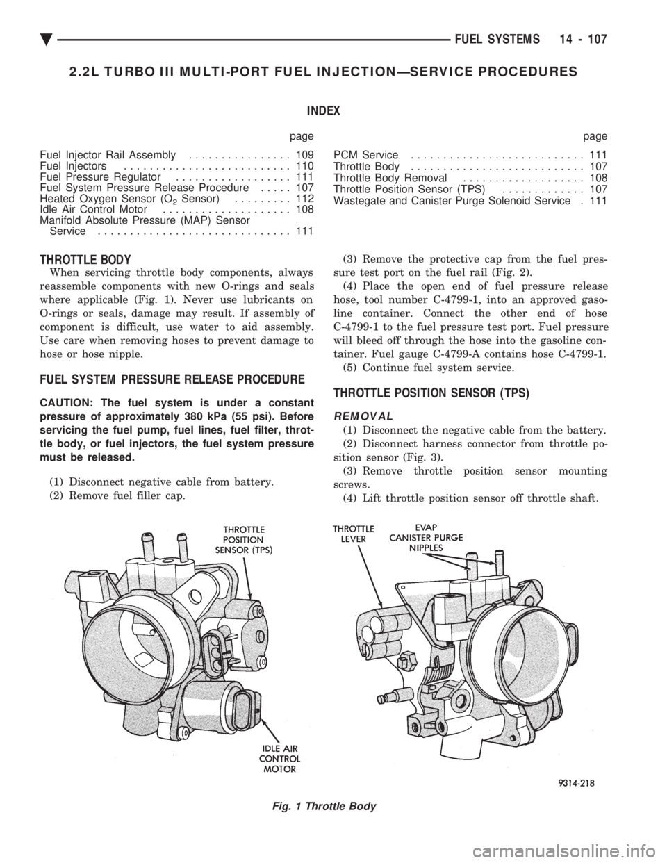
When servicing throttle body components, always
reassemble components with new O-rings and seals
where applicable (Fig. 1). Never use lubricants on
O-rings or seals, damage may result. If assembly of
component is difficult, use water to aid assembly.
Use care when removing hoses to prevent damage to
hose or hose nipple.
FUEL SYSTEM PRESSURE RELEASE PROCEDURE
CAUTION: The fuel system is under a constant
pressure of approximately 380 kPa (55 psi). Before
servicing the fuel pump, fuel lines, fuel filter, throt-
tle body, or fuel injectors, the fuel system pressure
must be released.
(1) Disconnect negative cable from battery.
(2) Remove fuel filler cap. (3) Remove the protective cap from the fuel pres-
sure test port on the fuel rail (Fig. 2). (4) Place the open end of fuel pressure release
hose, tool number C-4799-1, into an approved gaso-
line container. Connect the other end of hose
C-4799-1 to the fuel pressure test port. Fuel pressure
will bleed off through the hose into the gasoline con-
tainer. Fuel gauge C-4799-A contains hose C-4799-1. (5) Continue fuel system service.THROTTLE POSITION SENSOR (TPS)
REMOVAL
(1) Disconnect the negative cable from the battery.
(2) Disconnect harness connector from throttle po-
sition sensor (Fig. 3). (3) Remove throttle position sensor mounting
screws. (4) Lift throttle position sensor off throttle shaft.
Fig. 1 Throttle Body
Ä FUEL SYSTEMS 14 - 107