1993 CHEVROLET DYNASTY service
[x] Cancel search: servicePage 1850 of 2438
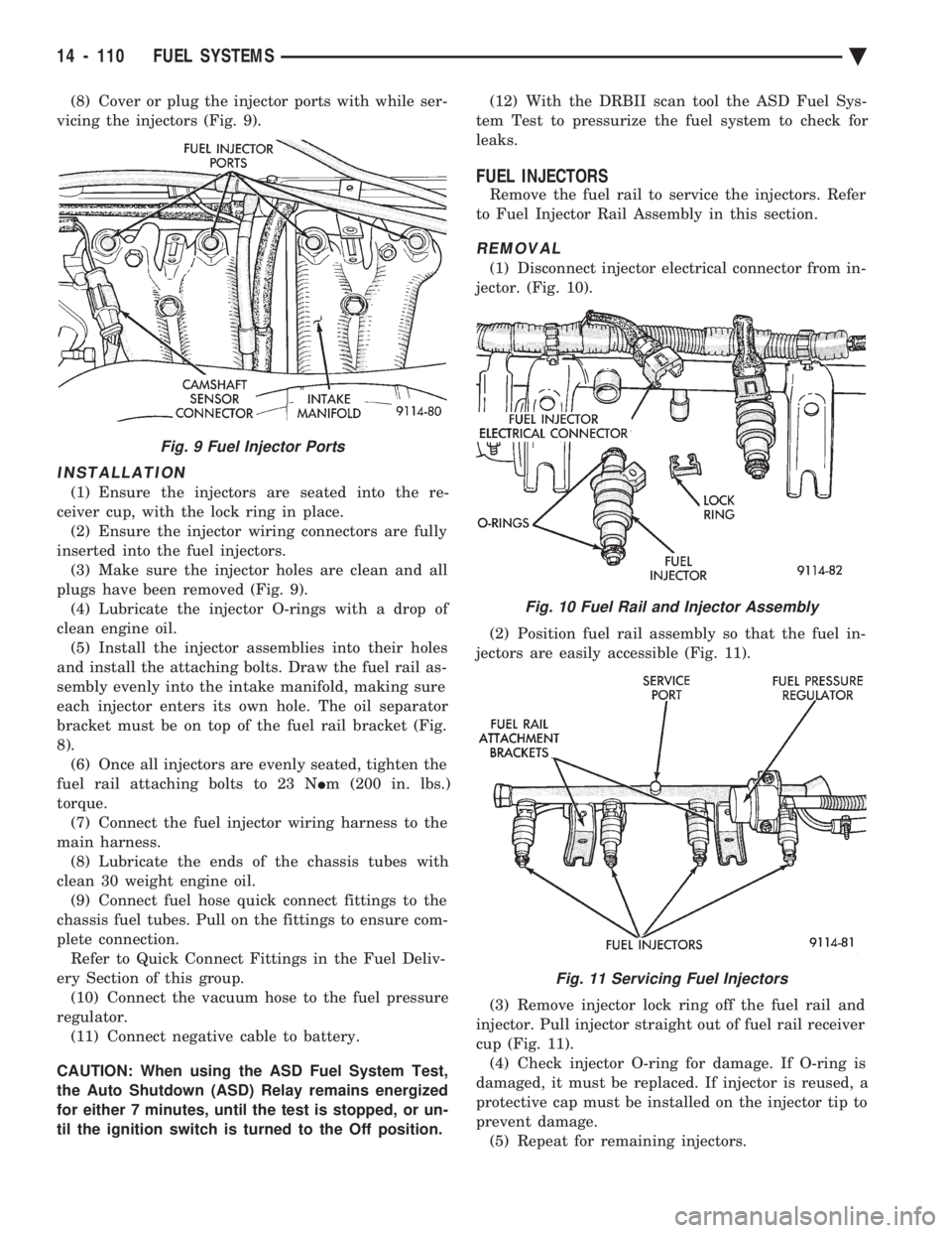
(8) Cover or plug the injector ports with while ser-
vicing the injectors (Fig. 9).
INSTALLATION
(1) Ensure the injectors are seated into the re-
ceiver cup, with the lock ring in place. (2) Ensure the injector wiring connectors are fully
inserted into the fuel injectors. (3) Make sure the injector holes are clean and all
plugs have been removed (Fig. 9). (4) Lubricate the injector O-rings with a drop of
clean engine oil. (5) Install the injector assemblies into their holes
and install the attaching bolts. Draw the fuel rail as-
sembly evenly into the intake manifold, making sure
each injector enters its own hole. The oil separator
bracket must be on top of the fuel rail bracket (Fig.
8). (6) Once all injectors are evenly seated, tighten the
fuel rail attaching bolts to 23 N Im (200 in. lbs.)
torque. (7) Connect the fuel injector wiring harness to the
main harness. (8) Lubricate the ends of the chassis tubes with
clean 30 weight engine oil. (9) Connect fuel hose quick connect fittings to the
chassis fuel tubes. Pull on the fittings to ensure com-
plete connection. Refer to Quick Connect Fittings in the Fuel Deliv-
ery Section of this group. (10) Connect the vacuum hose to the fuel pressure
regulator. (11) Connect negative cable to battery.
CAUTION: When using the ASD Fuel System Test,
the Auto Shutdown (ASD) Relay remains energized
for either 7 minutes, until the test is stopped, or un-
til the ignition switch is turned to the Off position. (12) With the DRBII scan tool the ASD Fuel Sys-
tem Test to pressurize the fuel system to check for
leaks.
FUEL INJECTORS
Remove the fuel rail to service the injectors. Refer
to Fuel Injector Rail Assembly in this section.
REMOVAL
(1) Disconnect injector electrical connector from in-
jector. (Fig. 10).
(2) Position fuel rail assembly so that the fuel in-
jectors are easily accessible (Fig. 11).
(3) Remove injector lock ring off the fuel rail and
injector. Pull injector straight out of fuel rail receiver
cup (Fig. 11). (4) Check injector O-ring for damage. If O-ring is
damaged, it must be replaced. If injector is reused, a
protective cap must be installed on the injector tip to
prevent damage. (5) Repeat for remaining injectors.
Fig. 9 Fuel Injector Ports
Fig. 10 Fuel Rail and Injector Assembly
Fig. 11 Servicing Fuel Injectors
14 - 110 FUEL SYSTEMS Ä
Page 1851 of 2438
INSTALLATION
(1) Before installing an injector, the rubber O-ring
must be lubricated with a drop of clean engine oil to aid
in installation. (2) Being careful not to damage the O-ring, install
injector top end into fuel rail receiver cup. (3) Install injector lock ring by sliding open end into
slot of the injector and onto the receiver cup ridge into
the side slots of ring (Fig. 11). (4) Repeat steps for remaining injectors.
(5) Install injector wiring harness to injectors. Place
harness into retaining clips.
FUEL PRESSURE REGULATOR
WARNING: THE 2.2L TURBO III FUEL SYSTEM IS
UNDER A CONSTANT PRESSURE OF APPROXI-
MATELY 380 KPA (55 PSI). PERFORM FUEL PRES-
SURE RELEASE PROCEDURE BEFORE SERVICING
THE FUEL PRESSURE REGULATOR.
REMOVAL
(1) Perform fuel system pressure release procedure.
(2) Disconnect negative cable from battery.
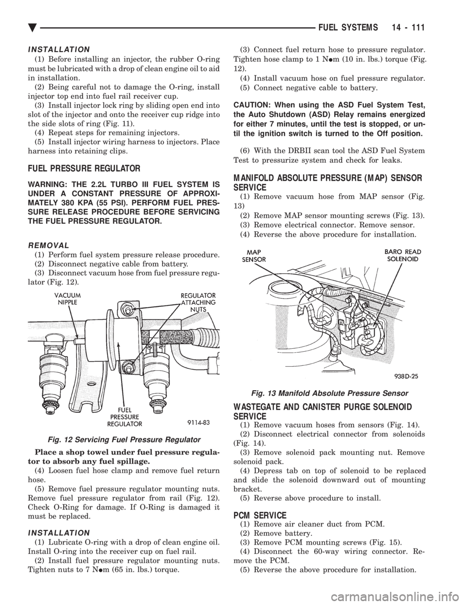
(3) Disconnect vacuum hose from fuel pressure regu-
lator (Fig. 12).
Place a shop towel under fuel pressure regula-
tor to absorb any fuel spillage. (4) Loosen fuel hose clamp and remove fuel return
hose. (5) Remove fuel pressure regulator mounting nuts.
Remove fuel pressure regulator from rail (Fig. 12).
Check O-Ring for damage. If O-Ring is damaged it
must be replaced.
INSTALLATION
(1) Lubricate O-ring with a drop of clean engine oil.
Install O-ring into the receiver cup on fuel rail. (2) Install fuel pressure regulator mounting nuts.
Tighten nuts to 7 N Im (65 in. lbs.) torque. (3) Connect fuel return hose to pressure regulator.
Tighten hose clamp to 1 N Im (10 in. lbs.) torque (Fig.
12). (4) Install vacuum hose on fuel pressure regulator.
(5) Connect negative cable to battery.
CAUTION: When using the ASD Fuel System Test,
the Auto Shutdown (ASD) Relay remains energized
for either 7 minutes, until the test is stopped, or un-
til the ignition switch is turned to the Off position. (6) With the DRBII scan tool the ASD Fuel System
Test to pressurize system and check for leaks.
MANIFOLD ABSOLUTE PRESSURE (MAP) SENSOR
SERVICE
(1) Remove vacuum hose from MAP sensor (Fig.
13) (2) Remove MAP sensor mounting screws (Fig. 13).
(3) Remove electrical connector. Remove sensor.
(4) Reverse the above procedure for installation.
WASTEGATE AND CANISTER PURGE SOLENOID
SERVICE
(1) Remove vacuum hoses from sensors (Fig. 14).
(2) Disconnect electrical connector from solenoids
(Fig. 14). (3) Remove solenoid pack mounting nut. Remove
solenoid pack. (4) Depress tab on top of solenoid to be replaced
and slide the solenoid downward out of mounting
bracket. (5) Reverse above procedure to install.
PCM SERVICE
(1) Remove air cleaner duct from PCM.
(2) Remove battery.
(3) Remove PCM mounting screws (Fig. 15).
(4) Disconnect the 60-way wiring connector. Re-
move the PCM. (5) Reverse the above procedure for installation.
Fig. 13 Manifold Absolute Pressure Sensor
Fig. 12 Servicing Fuel Pressure Regulator
Ä FUEL SYSTEMS 14 - 111
Page 1860 of 2438
MALFUNCTION INDICATOR LAMP (CHECK ENGINE
LAMP)ÐPCM OUTPUT
The malfunction indicator lamp (instrument panel
Check Engine lamp) comes on each time the ignition
key is turned ON and stays on for 3 seconds as a bulb
test. The malfunction indicator lamp warns the opera-
tor that the PCM has entered a Limp-in mode. During
Limp-in Mode, the PCM attempts to keep the system
operational. The malfunction indicator lamp signals
the need for immediate service. In limp-in mode, the
PCM compensates for the failure of certain components
that send incorrect signals. The PCM substitutes for
the incorrect signals with inputs from other sensors. Signals that can trigger the malfunction indi-
cator lamp (Check Engine Lamp).
² Engine Coolant Temperature Sensor
² Manifold Absolute Pressure Sensor
² Throttle Position Sensor
² Battery Voltage Input
² An Emission Related System (California vehicles)
² Charging system
The malfunction indicator lamp displays diagnostic
trouble codes. Cycle the ignition switch on, off, on, off,
on, within five seconds to display any diagnostic
trouble codes stored in the PCM. Refer to the 3.0L
Multi-Port Fuel InjectionÐOn-Board Diagnostics sec-
tion of this Group for Diagnostic trouble code Descrip-
tions.
DATA LINK CONNECTORÐPCM OUTPUT
The data link connector provides the technician with
the means to connect the DRBII scan tool to diagnosis
the vehicle.
TRANSAXLE CONTROL MODULEÐPCM OUTPUT
The PCM supplies the following information to the
electronic automatic transaxle control module through
the CCD Bus:
² battery temperature ²
brake switch input
² engine coolant temperature
² manifold absolute pressure (MAP)
² speed control information
FUEL INJECTORSÐPCM OUTPUT
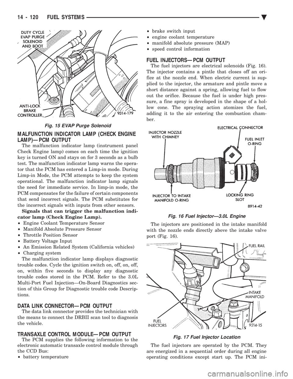
The fuel injectors are electrical solenoids (Fig. 16).
The injector contains a pintle that closes off an ori-
fice at the nozzle end. When electric current is sup-
plied to the injector, the armature and pintle move a
short distance against a spring, allowing fuel to flow
out the orifice. Because the fuel is under high pres-
sure, a fine spray is developed in the shape of a hol-
low cone. The spraying action atomizes the fuel,
adding it to the air entering the combustion cham-
ber.
The injectors are positioned in the intake manifold
with the nozzle ends directly above the intake valve
port (Fig. 16).
The fuel injectors are operated by the PCM. They
are energized in a sequential order during all engine
operating conditions except start up. The PCM ini-
Fig. 16 Fuel InjectorÐ3.0L Engine
Fig. 17 Fuel Injector Location
Fig. 15 EVAP Purge Solenoid
14 - 120 FUEL SYSTEMS Ä
Page 1878 of 2438
3.0L MULTI-PORT FUEL INJECTIONÐSERVICE PROCEDURES INDEX
page page
Idle Air Control Motor .................... 138
Canister Purge Solenoid Service ............ 143
Fuel Injector Rail Assembly ................ 139
Fuel Injectors .......................... 142
Fuel Pressure Regulator Service ............ 141
Fuel System Pressure Release Procedure ..... 138 Heated Oxygen Sensor (O
2Sensor)
......... 144
Manifold Absolute Pressure (MAP) Sensor ..... 143
PCM ................................. 143
Throttle Body ........................... 138
Throttle Body Service .................... 138
Throttle Position Sensor .................. 138
THROTTLE BODY SERVICE
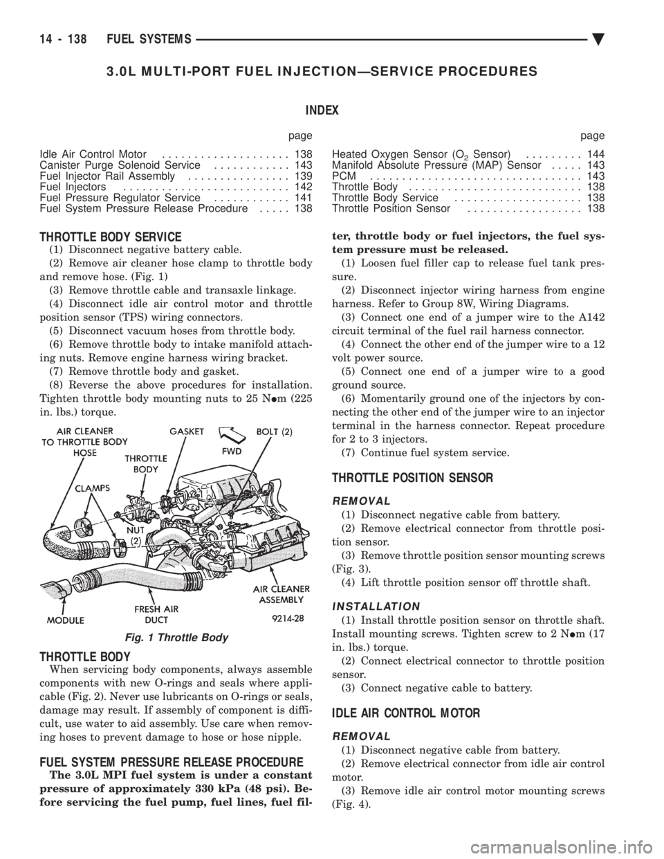
(1) Disconnect negative battery cable.
(2) Remove air cleaner hose clamp to throttle body
and remove hose. (Fig. 1) (3) Remove throttle cable and transaxle linkage.
(4) Disconnect idle air control motor and throttle
position sensor (TPS) wiring connectors. (5) Disconnect vacuum hoses from throttle body.
(6) Remove throttle body to intake manifold attach-
ing nuts. Remove engine harness wiring bracket. (7) Remove throttle body and gasket.
(8) Reverse the above procedures for installation.
Tighten throttle body mounting nuts to 25 N Im (225
in. lbs.) torque.
THROTTLE BODY
When servicing body components, always assemble
components with new O-rings and seals where appli-
cable (Fig. 2). Never use lubricants on O-rings or seals,
damage may result. If assembly of component is diffi-
cult, use water to aid assembly. Use care when remov-
ing hoses to prevent damage to hose or hose nipple.
FUEL SYSTEM PRESSURE RELEASE PROCEDURE
The 3.0L MPI fuel system is under a constant
pressure of approximately 330 kPa (48 psi). Be-
fore servicing the fuel pump, fuel lines, fuel fil- ter, throttle body or fuel injectors, the fuel sys-
tem pressure must be released. (1) Loosen fuel filler cap to release fuel tank pres-
sure. (2) Disconnect injector wiring harness from engine
harness. Refer to Group 8W, Wiring Diagrams. (3) Connect one end of a jumper wire to the A142
circuit terminal of the fuel rail harness connector. (4) Connect the other end of the jumper wire to a 12
volt power source. (5) Connect one end of a jumper wire to a good
ground source. (6) Momentarily ground one of the injectors by con-
necting the other end of the jumper wire to an injector
terminal in the harness connector. Repeat procedure
for 2 to 3 injectors. (7) Continue fuel system service.
THROTTLE POSITION SENSOR
REMOVAL
(1) Disconnect negative cable from battery.
(2) Remove electrical connector from throttle posi-
tion sensor. (3) Remove throttle position sensor mounting screws
(Fig. 3). (4) Lift throttle position sensor off throttle shaft.
INSTALLATION
(1) Install throttle position sensor on throttle shaft.
Install mounting screws. Tighten screw to 2 N Im (17
in. lbs.) torque. (2) Connect electrical connector to throttle position
sensor. (3) Connect negative cable to battery.
IDLE AIR CONTROL MOTOR
REMOVAL
(1) Disconnect negative cable from battery.
(2) Remove electrical connector from idle air control
motor. (3) Remove idle air control motor mounting screws
(Fig. 4).
Fig. 1 Throttle Body
14 - 138 FUEL SYSTEMS Ä
Page 1881 of 2438
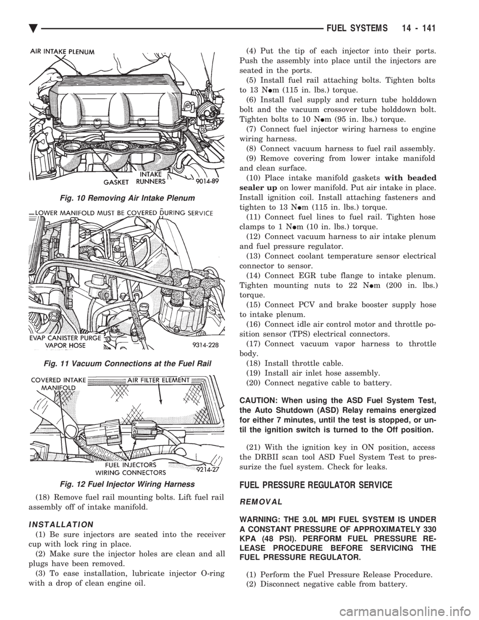
(18) Remove fuel rail mounting bolts. Lift fuel rail
assembly off of intake manifold.
INSTALLATION
(1) Be sure injectors are seated into the receiver
cup with lock ring in place. (2) Make sure the injector holes are clean and all
plugs have been removed. (3) To ease installation, lubricate injector O-ring
with a drop of clean engine oil. (4) Put the tip of each injector into their ports.
Push the assembly into place until the injectors are
seated in the ports. (5) Install fuel rail attaching bolts. Tighten bolts
to 13 N Im (115 in. lbs.) torque.
(6) Install fuel supply and return tube holddown
bolt and the vacuum crossover tube holddown bolt.
Tighten bolts to 10 N Im (95 in. lbs.) torque.
(7) Connect fuel injector wiring harness to engine
wiring harness. (8) Connect vacuum harness to fuel rail assembly.
(9) Remove covering from lower intake manifold
and clean surface. (10) Place intake manifold gaskets with beaded
sealer up on lower manifold. Put air intake in place.
Install ignition coil. Install attaching fasteners and
tighten to 13 N Im (115 in. lbs.) torque.
(11) Connect fuel lines to fuel rail. Tighten hose
clamps to 1 N Im (10 in. lbs.) torque.
(12) Connect vacuum harness to air intake plenum
and fuel pressure regulator. (13) Connect coolant temperature sensor electrical
connector to sensor. (14) Connect EGR tube flange to intake plenum.
Tighten mounting nuts to 22 N Im (200 in. lbs.)
torque. (15) Connect PCV and brake booster supply hose
to intake plenum. (16) Connect idle air control motor and throttle po-
sition sensor (TPS) electrical connectors. (17) Connect vacuum vapor harness to throttle
body. (18) Install throttle cable.
(19) Install air inlet hose assembly.
(20) Connect negative cable to battery.
CAUTION: When using the ASD Fuel System Test,
the Auto Shutdown (ASD) Relay remains energized
for either 7 minutes, until the test is stopped, or un-
til the ignition switch is turned to the Off position. (21) With the ignition key in ON position, access
the DRBII scan tool ASD Fuel System Test to pres-
surize the fuel system. Check for leaks.
FUEL PRESSURE REGULATOR SERVICE
REMOVAL
WARNING: THE 3.0L MPI FUEL SYSTEM IS UNDER
A CONSTANT PRESSURE OF APPROXIMATELY 330
KPA (48 PSI). PERFORM FUEL PRESSURE RE-
LEASE PROCEDURE BEFORE SERVICING THE
FUEL PRESSURE REGULATOR.
(1) Perform the Fuel Pressure Release Procedure.
(2) Disconnect negative cable from battery.
Fig. 10 Removing Air Intake Plenum
Fig. 11 Vacuum Connections at the Fuel Rail
Fig. 12 Fuel Injector Wiring Harness
Ä FUEL SYSTEMS 14 - 141
Page 1882 of 2438
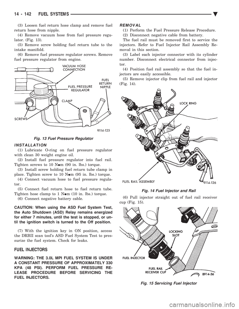
(3) Loosen fuel return hose clamp and remove fuel
return hose from nipple. (4) Remove vacuum hose from fuel pressure regu-
lator. (Fig. 13). (5) Remove screw holding fuel return tube to the
intake manifold. (6) Remove fuel pressure regulator screws. Remove
fuel pressure regulator from engine.
INSTALLATION
(1) Lubricate O-ring on fuel pressure regulator
with clean 30 weight engine oil. (2) Install fuel pressure regulator into fuel rail.
Tighten screws to 10 N Im (90 in. lbs.) torque.
(3) Install screw holding fuel return tube clamp in
place. Tighten screw to 10 N Im (95 in. lbs.) torque.
(4) Connect vacuum hose to fuel pressure regula-
tor. (5) Connect fuel return hose to fuel return tube.
Tighten hose clamp to 1 N Im (10 in. lbs.) torque.
(6) Connect negative battery cable.
CAUTION: When using the ASD Fuel System Test,
the Auto Shutdown (ASD) Relay remains energized
for either 7 minutes, until the test is stopped, or un-
til the ignition switch is turned to the Off position.
(7) With the ignition key in ON position, access
the DRBII scan tool's ASD Fuel System Test to pres-
surize the fuel system. Check for leaks.
FUEL INJECTORS
WARNING: THE 3.0L MPI FUEL SYSTEM IS UNDER
A CONSTANT PRESSURE OF APPROXIMATELY 330
KPA (48 PSI). PERFORM FUEL PRESSURE RE-
LEASE PROCEDURE BEFORE SERVICING THE
FUEL INJECTORS.
REMOVAL
(1) Perform the Fuel Pressure Release Procedure.
(2) Disconnect negative cable from battery.
The fuel rail must be removed first to service the
injectors. Refer to Fuel Injector Rail Assembly Re-
moval in this section. (3) Label each injector connector with its cylinder
number. Disconnect electrical connector from injec-
tor. (4) Position fuel rail assembly so that the fuel in-
jectors are easily accessible. (5) Remove injector clip from fuel rail and injector
(Fig. 14).
(6) Pull injector straight out of fuel rail receiver
cup (Fig. 15).
Fig. 13 Fuel Pressure Regulator
Fig. 14 Fuel Injector and Rail
Fig. 15 Servicing Fuel Injector
14 - 142 FUEL SYSTEMS Ä
Page 1883 of 2438
(7) Check injector O-ring for damage. If O-ring is
damaged, it must be replaced. If injector is to be re-
used, a protective cap must be installed on the injec-
tor tip to prevent damage. (8) Repeat procedure for remaining injectors.
INSTALLATION
(1) Before installing an injector, the rubber O-ring
must be lubricated with a drop of clean engine oil to
aid in installation. (2) Being careful not to damage O-ring, install in-
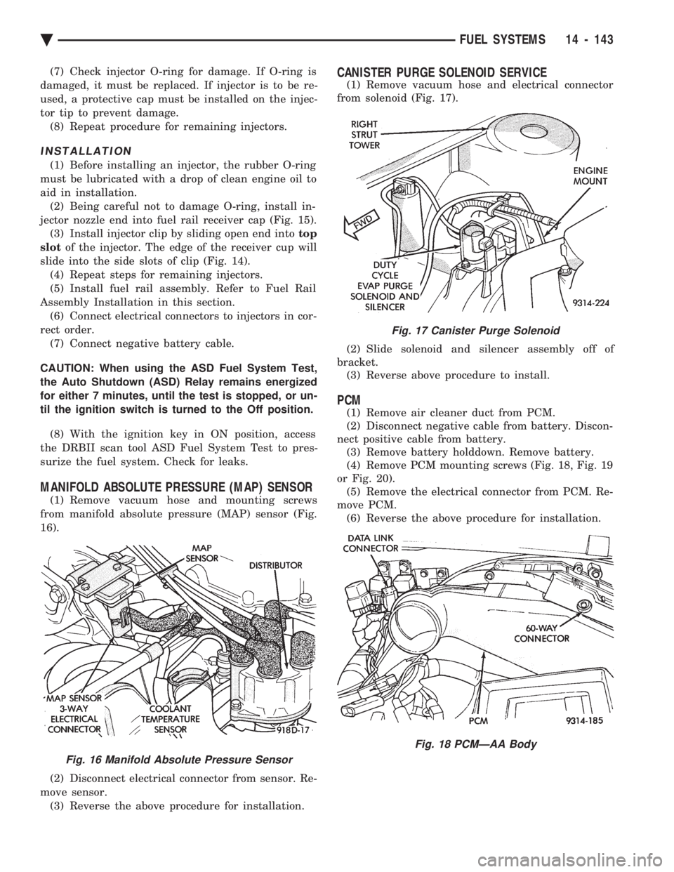
jector nozzle end into fuel rail receiver cap (Fig. 15). (3) Install injector clip by sliding open end into top
slot of the injector. The edge of the receiver cup will
slide into the side slots of clip (Fig. 14). (4) Repeat steps for remaining injectors.
(5) Install fuel rail assembly. Refer to Fuel Rail
Assembly Installation in this section. (6) Connect electrical connectors to injectors in cor-
rect order. (7) Connect negative battery cable.
CAUTION: When using the ASD Fuel System Test,
the Auto Shutdown (ASD) Relay remains energized
for either 7 minutes, until the test is stopped, or un-
til the ignition switch is turned to the Off position.
(8) With the ignition key in ON position, access
the DRBII scan tool ASD Fuel System Test to pres-
surize the fuel system. Check for leaks.
MANIFOLD ABSOLUTE PRESSURE (MAP) SENSOR
(1) Remove vacuum hose and mounting screws
from manifold absolute pressure (MAP) sensor (Fig.
16).
(2) Disconnect electrical connector from sensor. Re-
move sensor. (3) Reverse the above procedure for installation.
CANISTER PURGE SOLENOID SERVICE
(1) Remove vacuum hose and electrical connector
from solenoid (Fig. 17).
(2) Slide solenoid and silencer assembly off of
bracket. (3) Reverse above procedure to install.
PCM
(1) Remove air cleaner duct from PCM.
(2) Disconnect negative cable from battery. Discon-
nect positive cable from battery. (3) Remove battery holddown. Remove battery.
(4) Remove PCM mounting screws (Fig. 18, Fig. 19
or Fig. 20). (5) Remove the electrical connector from PCM. Re-
move PCM. (6) Reverse the above procedure for installation.
Fig. 16 Manifold Absolute Pressure Sensor
Fig. 17 Canister Purge Solenoid
Fig. 18 PCMÐAA Body
Ä FUEL SYSTEMS 14 - 143
Page 1888 of 2438
to low. The number of notches determine the amount of
pulses. If available, an oscilloscope can display the
square wave patterns of each timing events. Top dead center (TDC) does not occur when notches
on the camshaft sprocket pass below the cylinder. TDC
occurs after the camshaft pulse (or pulses) and after
the 4 crankshaft pulses associated with the particular
cylinder. The arrows and cylinder call outs on Figure 4
represent which cylinder the flat spot and notches
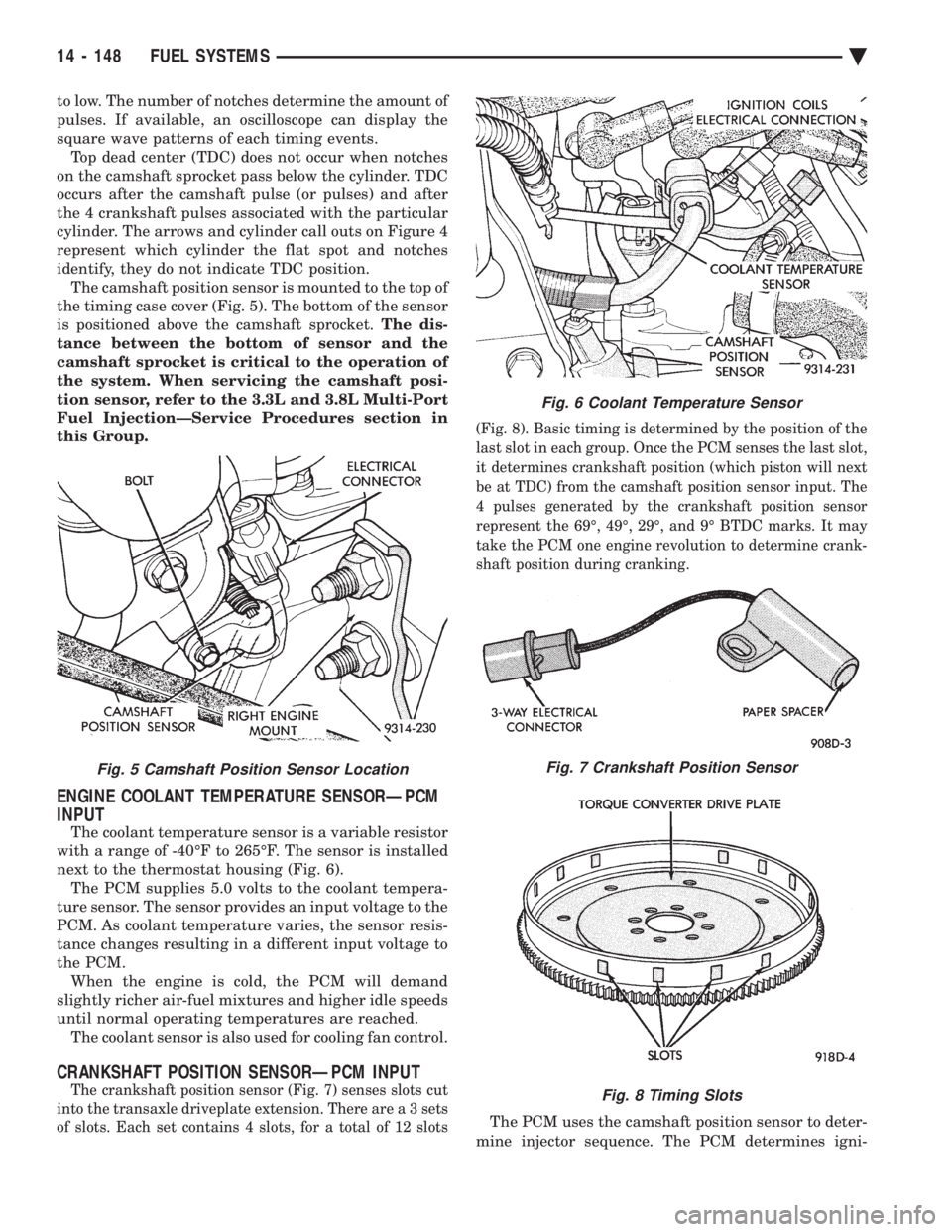
identify, they do not indicate TDC position. The camshaft position sensor is mounted to the top of
the timing case cover (Fig. 5). The bottom of the sensor
is positioned above the camshaft sprocket. The dis-
tance between the bottom of sensor and the
camshaft sprocket is critical to the operation of
the system. When servicing the camshaft posi-
tion sensor, refer to the 3.3L and 3.8L Multi-Port
Fuel InjectionÐService Procedures section in
this Group.
ENGINE COOLANT TEMPERATURE SENSORÐPCM
INPUT
The coolant temperature sensor is a variable resistor
with a range of -40ÉF to 265ÉF. The sensor is installed
next to the thermostat housing (Fig. 6). The PCM supplies 5.0 volts to the coolant tempera-
ture sensor. The sensor provides an input voltage to the
PCM. As coolant temperature varies, the sensor resis-
tance changes resulting in a different input voltage to
the PCM. When the engine is cold, the PCM will demand
slightly richer air-fuel mixtures and higher idle speeds
until normal operating temperatures are reached. The coolant sensor is also used for cooling fan control.
CRANKSHAFT POSITION SENSORÐPCM INPUT
The crankshaft position sensor (Fig. 7) senses slots cut
into the transaxle driveplate extension. There ar e a 3 sets
of slots. Each set contains 4 slots, for a total of 12 slots (Fig. 8). Basic timing is determined by the position of the
last slot in each group. Once the PCM senses the last slot,
it determines crankshaft position (which piston will next
be at TDC) from the camshaft position sensor input. The
4 pulses generated by the crankshaft position sensor
represent the 69É, 49É, 29É, and 9É BTDC marks. It may
take the PCM one engine revolution to determine crank-
shaft position during cranking.
The PCM uses the camshaft position sensor to deter-
mine injector sequence. The PCM determines igni-
Fig. 5 Camshaft Position Sensor Location
Fig. 6 Coolant Temperature Sensor
Fig. 7 Crankshaft Position Sensor
Fig. 8 Timing Slots
14 - 148 FUEL SYSTEMS Ä