1993 CHEVROLET DYNASTY service
[x] Cancel search: servicePage 1948 of 2438
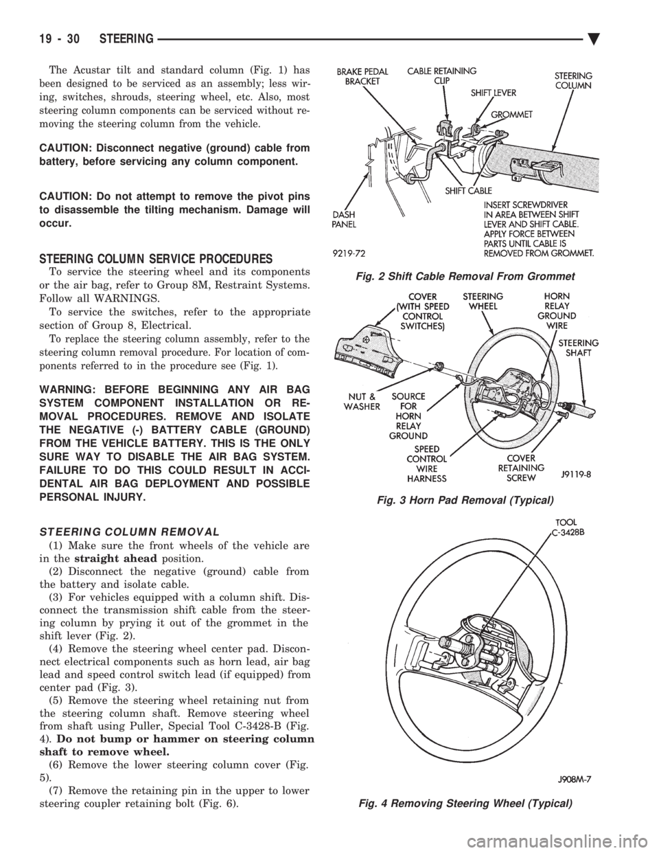
The Acustar tilt and standard column (Fig. 1) has
been designed to be serviced as an assembly; less wir-
ing, switches, shrouds, steering wheel, etc. Also, most
steering column components can be serviced without re-
moving the steering column from the vehicle.
CAUTION: Disconnect negative (ground) cable from
battery, before servicing any column component.
CAUTION: Do not attempt to remove the pivot pins
to disassemble the tilting mechanism. Damage will
occur.
STEERING COLUMN SERVICE PROCEDURES
To service the steering wheel and its components
or the air bag, refer to Group 8M, Restraint Systems.
Follow all WARNINGS. To service the switches, refer to the appropriate
section of Group 8, Electrical.
To replace the steering column assembly, refer to the
steering column removal procedure. For location of com-
ponents referred to in the procedure see (Fig. 1).
WARNING: BEFORE BEGINNING ANY AIR BAG
SYSTEM COMPONENT INSTALLATION OR RE-
MOVAL PROCEDURES. REMOVE AND ISOLATE
THE NEGATIVE (-) BATTERY CABLE (GROUND)
FROM THE VEHICLE BATTERY. THIS IS THE ONLY
SURE WAY TO DISABLE THE AIR BAG SYSTEM.
FAILURE TO DO THIS COULD RESULT IN ACCI-
DENTAL AIR BAG DEPLOYMENT AND POSSIBLE
PERSONAL INJURY.
STEERING COLUMN REMOVAL
(1) Make sure the front wheels of the vehicle are
in the straight ahead position.
(2) Disconnect the negative (ground) cable from
the battery and isolate cable. (3) For vehicles equipped with a column shift. Dis-
connect the transmission shift cable from the steer-
ing column by prying it out of the grommet in the
shift lever (Fig. 2). (4) Remove the steering wheel center pad. Discon-
nect electrical components such as horn lead, air bag
lead and speed control switch lead (if equipped) from
center pad (Fig. 3). (5) Remove the steering wheel retaining nut from
the steering column shaft. Remove steering wheel
from shaft using Puller, Special Tool C-3428-B (Fig.
4). Do not bump or hammer on steering column
shaft to remove wheel. (6) Remove the lower steering column cover (Fig.
5). (7) Remove the retaining pin in the upper to lower
steering coupler retaining bolt (Fig. 6).
Fig. 2 Shift Cable Removal From Grommet
Fig. 3 Horn Pad Removal (Typical)
Fig. 4 Removing Steering Wheel (Typical)
19 - 30 STEERING Ä
Page 1952 of 2438
(16) Connect the battery ground (negative) cable.
Test the operation of the lights and horns. If applica-
ble, reset the clock and radio.
STEERING COLUMN COMPONENT SERVICE
The Acustar tilt and standard steering columns
(Fig.1) have been designed to be serviced as an as-
sembly; less wiring, switches, shrouds, steering
wheel, etc. Also most steering column components
can be serviced without removing the steering col-
umn from the vehicle. For additional information on
electrical components refer to Group 8H Electrical.
GEAR SHIFT LEVER
The gear shift lever (if equipped) is a serviceable
component of the Acustar steering column assembly.
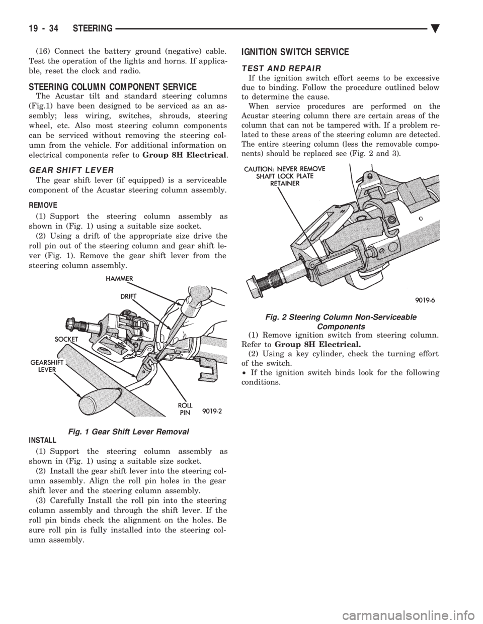
REMOVE (1) Support the steering column assembly as
shown in (Fig. 1) using a suitable size socket. (2) Using a drift of the appropriate size drive the
roll pin out of the steering column and gear shift le-
ver (Fig. 1). Remove the gear shift lever from the
steering column assembly.
INSTALL (1) Support the steering column assembly as
shown in (Fig. 1) using a suitable size socket. (2) Install the gear shift lever into the steering col-
umn assembly. Align the roll pin holes in the gear
shift lever and the steering column assembly. (3) Carefully Install the roll pin into the steering
column assembly and through the shift lever. If the
roll pin binds check the alignment on the holes. Be
sure roll pin is fully installed into the steering col-
umn assembly.
IGNITION SWITCH SERVICE
TEST AND REPAIR
If the ignition switch effort seems to be excessive
due to binding. Follow the procedure outlined below
to determine the cause.
When service procedures are performed on the
Acustar steering column there are certain areas of the
column that can not be tampered with. If a problem re-
lated to these areas of the steering column are detected.
The entire steering column (less the removable compo-
nents) should be replaced see (Fig. 2 and 3).
(1) Remove ignition switch from steering column.
Refer to Group 8H Electrical.
(2) Using a key cylinder, check the turning effort
of the switch.
² If the ignition switch binds look for the following
conditions.
Fig. 1 Gear Shift Lever Removal
Fig. 2 Steering Column Non-Serviceable Components
19 - 34 STEERING Ä
Page 1953 of 2438
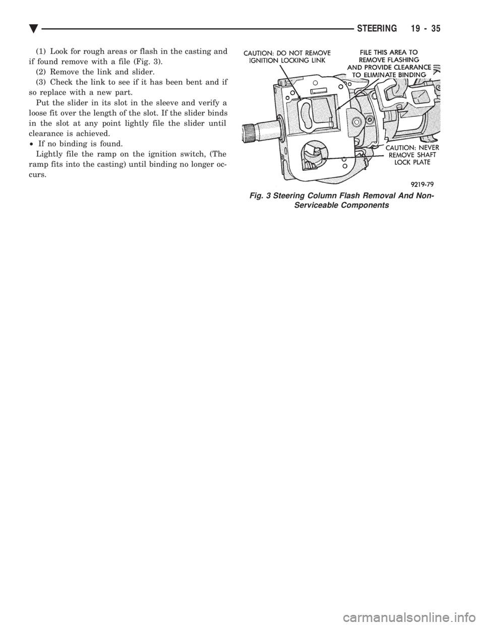
(1) Look for rough areas or flash in the casting and
if found remove with a file (Fig. 3). (2) Remove the link and slider.
(3) Check the link to see if it has been bent and if
so replace with a new part. Put the slider in its slot in the sleeve and verify a
loose fit over the length of the slot. If the slider binds
in the slot at any point lightly file the slider until
clearance is achieved.
² If no binding is found.
Lightly file the ramp on the ignition switch, (The
ramp fits into the casting) until binding no longer oc-
curs.
Fig. 3 Steering Column Flash Removal And Non- Serviceable Components
Ä STEERING 19 - 35
Page 1954 of 2438
AUTOMATIC TRANSMISSION SHIFTER/IGNITION INTERLOCK INDEX
page page
General Information ....................... 36
Interlock System Adjustment ................ 37 Interlock System Operation Check
............ 36
Shifter/Ignition Interlock Cable ............... 38
GENERAL INFORMATION
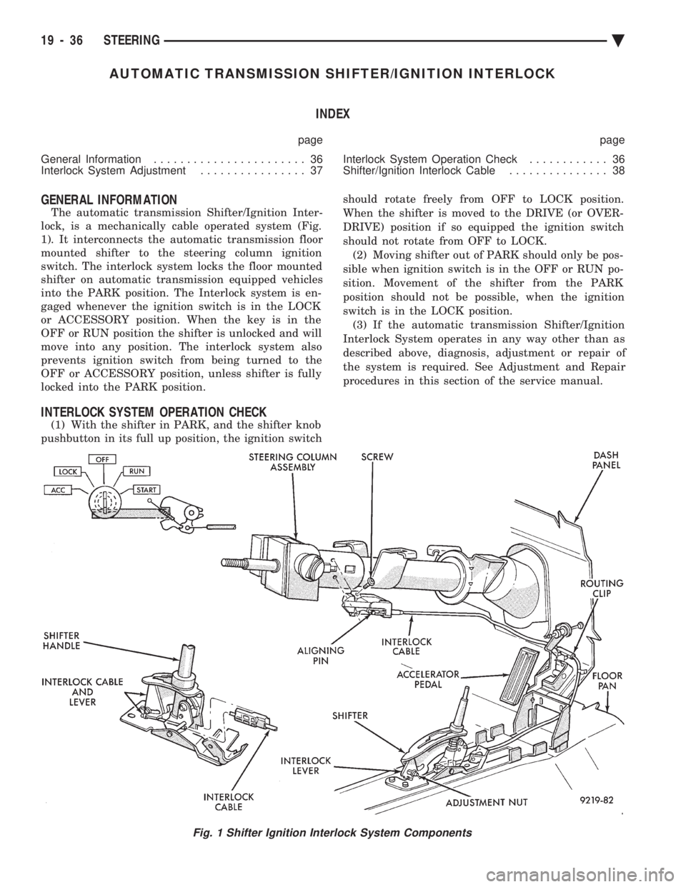
The automatic transmission Shifter/Ignition Inter-
lock, is a mechanically cable operated system (Fig.
1). It interconnects the automatic transmission floor
mounted shifter to the steering column ignition
switch. The interlock system locks the floor mounted
shifter on automatic transmission equipped vehicles
into the PARK position. The Interlock system is en-
gaged whenever the ignition switch is in the LOCK
or ACCESSORY position. When the key is in the
OFF or RUN position the shifter is unlocked and will
move into any position. The interlock system also
prevents ignition switch from being turned to the
OFF or ACCESSORY position, unless shifter is fully
locked into the PARK position.
INTERLOCK SYSTEM OPERATION CHECK
(1) With the shifter in PARK, and the shifter knob
pushbutton in its full up position, the ignition switch should rotate freely from OFF to LOCK position.
When the shifter is moved to the DRIVE (or OVER-
DRIVE) position if so equipped the ignition switch
should not rotate from OFF to LOCK. (2) Moving shifter out of PARK should only be pos-
sible when ignition switch is in the OFF or RUN po-
sition. Movement of the shifter from the PARK
position should not be possible, when the ignition
switch is in the LOCK position. (3) If the automatic transmission Shifter/Ignition
Interlock System operates in any way other than as
described above, diagnosis, adjustment or repair of
the system is required. See Adjustment and Repair
procedures in this section of the service manual.
Fig. 1 Shifter Ignition Interlock System Components
19 - 36 STEERING Ä
Page 1955 of 2438
INTERLOCK SYSTEM ADJUSTMENT
If ignition switch is binding, operating effort high or
can not be turned to the LOCK position, with shifter locked
in PARK, adjustment of Interlock System may be
required. To adjust Interlock System, follow procedure
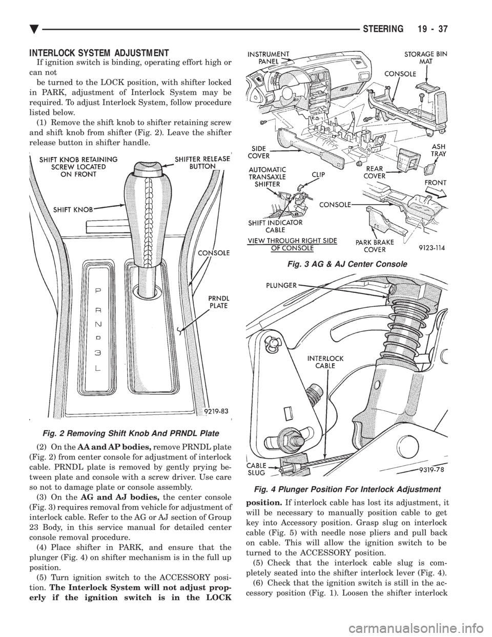
listed below. (1) Remove the shift knob to shifter retaining screw
and shift knob from shifter (Fig. 2). Leave the shifter
release button in shifter handle.
(2) On the AA and AP bodies, remove PRNDL plate
(Fig. 2) from center console for adjustment of interlock
cable. PRNDL plate is removed by gently prying be-
tween plate and console with a screw driver. Use care
so not to damage plate or console assembly. (3) On the AG and AJ bodies, the center console
(Fig. 3) requires removal from vehicle for adjustment of
interlock cable. Refer to the AG or AJ section of Group
23 Body, in this service manual for detailed center
console removal procedure. (4) Place shifter in PARK, and ensure that the
plunger (Fig. 4) on shifter mechanism is in the full up
position. (5) Turn ignition switch to the ACCESSORY posi-
tion. The Interlock System will not adjust prop-
erly if the ignition switch is in the LOCK position.
If interlock cable has lost its adjustment, it
will be necessary to manually position cable to get
key into Accessory position. Grasp slug on interlock
cable (Fig. 5) with needle nose pliers and pull back
on cable. This will allow the ignition switch to be
turned to the ACCESSORY position. (5) Check that the interlock cable slug is com-
pletely seated into the shifter interlock lever (Fig. 4). (6) Check that the ignition switch is still in the ac-
cessory position (Fig. 1). Loosen the shifter interlock
Fig. 3 AG & AJ Center Console
Fig. 4 Plunger Position For Interlock Adjustment
Fig. 2 Removing Shift Knob And PRNDL Plate
Ä STEERING 19 - 37
Page 1956 of 2438
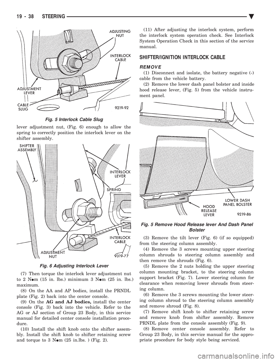
lever adjustment nut, (Fig. 6) enough to allow the
spring to correctly position the interlock lever on the
shifter assembly.
(7) Then torque the interlock lever adjustment nut
to2N Im (15 in. lbs.) minimum 3 N Im (25 in. lbs.)
maximum. (8) On the AA and AP bodies, install the PRNDL
plate (Fig. 2) back into the center console. (9) On the AG and AJ bodies, install the center
console (Fig. 3) back into the vehicle. Refer to the
AG or AJ section of Group 23 Body, in this service
manual for detailed center console installation proce-
dure. (10) Install the shift knob onto the shifter assem-
bly. Install the shift knob to shifter retaining screw
and torque to 3 N Im (25 in.lbs. ) (Fig. 2). (11) After adjusting the interlock system, perform
the interlock system operation check. See Interlock
System Operation Check in this section of the service
manual.
SHIFTER/IGNITION INTERLOCK CABLE
REMOVE
(1) Disconnect and isolate, the battery negative (-)
cable from the vehicle battery. (2) Remove the lower dash panel bolster and inside
hood release lever, (Fig. 5) from the vehicle instru-
ment panel.
(3) Remove the tilt lever (Fig. 6) (if so equipped)
from the steering column assembly. (4) Remove the 3 screws mounting upper steering
column shrouds to steering column assembly and
then remove the shrouds (Fig. 6). (5) Remove the 2 nuts holding the upper steering
column mounting bracket, to the steering column
support bracket (Fig. 7). Lower steering column for
clearance when removing lower shrouds from steer-
ing column. (6) Remove the 3 screws mounting the lower steer-
ing column shroud to the steering column assembly
and remove shroud (Fig. 8). (7) Remove shift knob to shifter retaining screw
and remove knob from shifter assembly. Remove
PRNDL plate from the console assembly (Fig. 9). (8) Remove center console assembly. Refer to
Group 23 Body, in this service manual for the appro-
priate procedure for body style being serviced.
Fig. 5 Interlock Cable Slug
Fig. 6 Adjusting Interlock Lever
Fig. 5 Remove Hood Release lever And Dash Panel Bolster
19 - 38 STEERING Ä
Page 1959 of 2438
CAUTION: Interlock cable must by completely
clipped to the throttle pedal bracket with both barbs
of clip fully installed through mounting holes. This
is to prevent interference with throttle pedal.
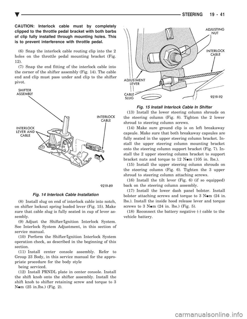
(6) Snap the interlock cable routing clip into the 2
holes on the throttle pedal mounting bracket (Fig.
12). (7) Snap the end fitting of the interlock cable into
the corner of the shifter assembly (Fig. 14). The cable
end and clip must pass under and clip to the shifter
pivot.
(8) Install slug on end of interlock cable into notch,
on shifter lockout spring loaded lever (Fig. 15). Make
sure that cable slug is fully seated in cup of lever as-
sembly. (9) Adjust the Shifter/Ignition Interlock System.
See Interlock System Adjustment, in this section of
service manual. (10) Perform the Shifter/Ignition Interlock System
operation check, as described in the beginning of this
section. (11) Install center console assembly. Refer to
Group 23 Body, in this service manual for the appro-
priate procedure for the body style being serviced.
(12) Install PRNDL plate in center console. Install
the shift knob onto the shifter assembly. Install the
shift knob to shifter retaining screw and torque to 3
N Im (25 in.lbs.) (Fig. 2). (13) Install the lower steering column shrouds on
the steering column (Fig. 8). Tighten the 2 lower
shroud to steering column screws. (14) Make sure ground clip is on left breakaway
capsule. Make sure that both breakaway capsules are
fully seated in the upper steering column bracket. In-
stall the upper steering column mounting bracket
onto the steering column support bracket (Fig. 7). In-
stall the 2 upper steering column bracket to support
bracket nuts and torque to 12 N Im (105 in. lbs.).
(15) Install the upper steering column shrouds on
the steering column (Fig. 6). Tighten the 3 upper
shroud to steering column attaching screws. (16) Install the tilt lever (Fig. 6) (if so equipped)
back on the steering column assembly. (17) Install the lower dash panel bolster. Install
bolster attaching screws and torque to 3 N Im (24 in.
lbs.). Install the inside hood release lever and torque
screws to 3 N Im (24 in. lbs.) (Fig. 5).
(18) Reconnect the battery negative (-) cable to the
vehicle battery.
Fig. 14 Interlock Cable Installation
Fig. 15 Install Interlock Cable In Shifter
Ä STEERING 19 - 41
Page 1962 of 2438
A-568 HEAVYÐDUTY MANUAL TRANSAXLE
The greater torque of the high output turbo engines
require a stronger transmission. It includes a die-cast
aluminum case and a stronger, coarse-pitch gear set. It
has five forward speed ratios and reverse. Gear ratios
are as follows: 1stÐ3.31, 2ndÐ1.89, 3rdÐ1.28,
4thÐ0.94, 5thÐ0.71, ReverseÐ3.14. Final drive ratio
of 3.85 was selected for maximum performance. All
forward gears are synchronized. To reduce wear, this transaxle, in common with other
manual transaxles, uses SAE 5W-30 engine oil as the
lubricant.
IDENTIFICATION
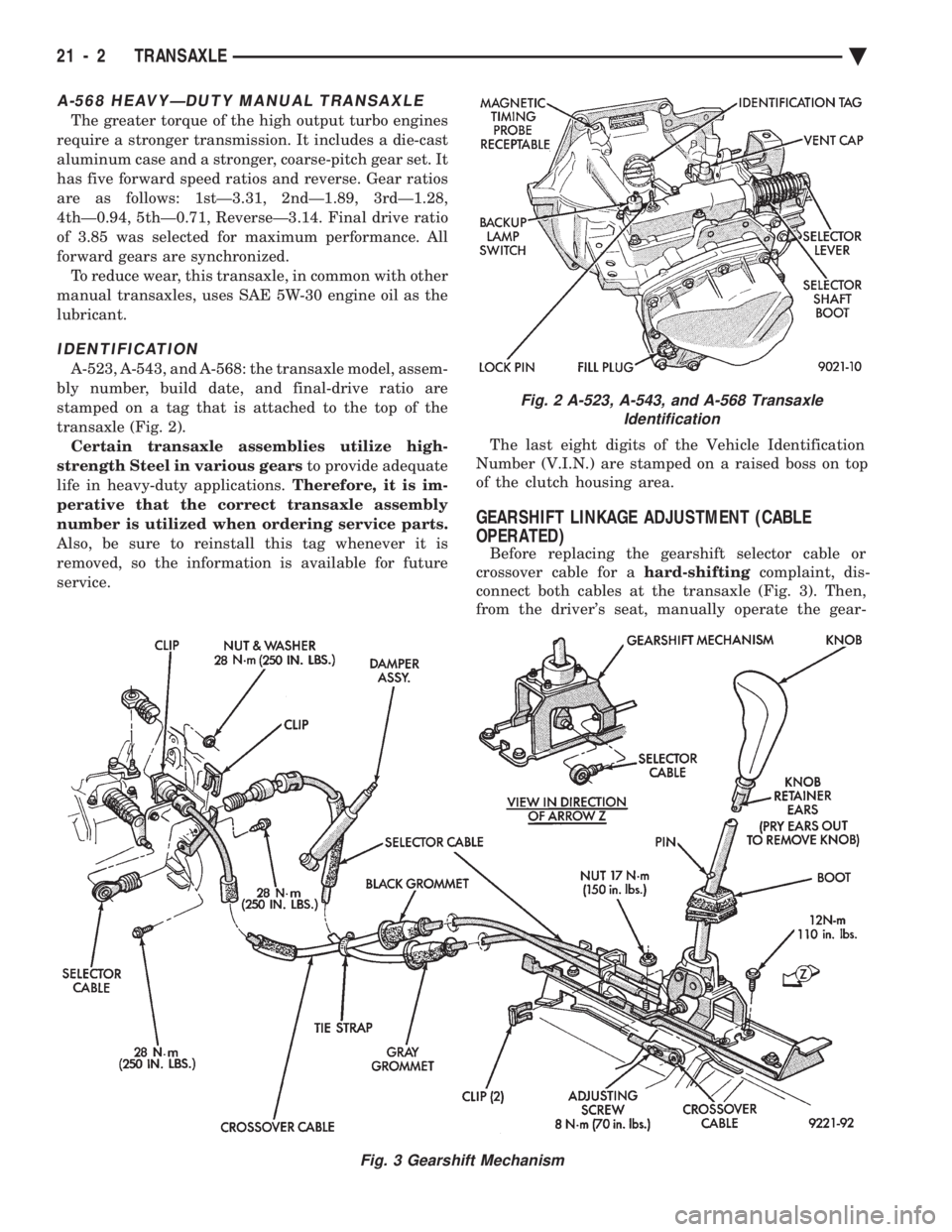
A-523, A-543, and A-568: the transaxle model, assem-
bly number, build date, and final-drive ratio are
stamped on a tag that is attached to the top of the
transaxle (Fig. 2). Certain transaxle assemblies utilize high-
strength Steel in various gears to provide adequate
life in heavy-duty applications. Therefore, it is im-
perative that the correct transaxle assembly
number is utilized when ordering service parts.
Also, be sure to reinstall this tag whenever it is
removed, so the information is available for future
service. The last eight digits of the Vehicle Identification
Number (V.I.N.) are stamped on a raised boss on top
of the clutch housing area.
GEARSHIFT LINKAGE ADJUSTMENT (CABLE
OPERATED)
Before replacing the gearshift selector cable or
crossover cable for a hard-shiftingcomplaint, dis-
connect both cables at the transaxle (Fig. 3). Then,
from the driver's seat, manually operate the gear-
Fig. 2 A-523, A-543, and A-568 Transaxle Identification
Fig. 3 Gearshift Mechanism
21 - 2 TRANSAXLE Ä