1993 CHEVROLET DYNASTY service
[x] Cancel search: servicePage 1964 of 2438
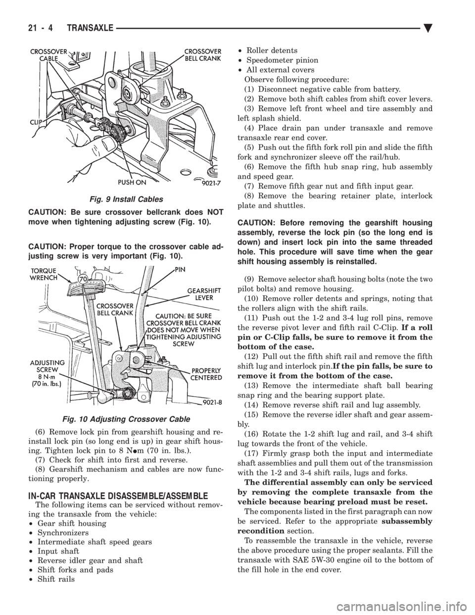
CAUTION: Be sure crossover bellcrank does NOT
move when tightening adjusting screw (Fig. 10).
CAUTION: Proper torque to the crossover cable ad-
justing screw is very important (Fig. 10).
(6) Remove lock pin from gearshift housing and re-
install lock pin (so long end is up) in gear shift hous-
ing. Tighten lock pin to 8 N Im (70 in. lbs.).
(7) Check for shift into first and reverse.
(8) Gearshift mechanism and cables are now func-
tioning properly.
IN-CAR TRANSAXLE DISASSEMBLE/ASSEMBLE
The following items can be serviced without remov-
ing the transaxle from the vehicle:
² Gear shift housing
² Synchronizers
² Intermediate shaft speed gears
² Input shaft
² Reverse idler gear and shaft
² Shift forks and pads
² Shift rails ²
Roller detents
² Speedometer pinion
² All external covers
Observe following procedure:
(1) Disconnect negative cable from battery.
(2) Remove both shift cables from shift cover levers.
(3) Remove left front wheel and tire assembly and
left splash shield. (4) Place drain pan under transaxle and remove
transaxle rear end cover. (5) Push out the fifth fork roll pin and slide the fifth
fork and synchronizer sleeve off the rail/hub. (6) Remove the fifth hub snap ring, hub assembly
and speed gear. (7) Remove fifth gear nut and fifth input gear.
(8) Remove the bearing retainer plate, interlock
plate and shuttles.
CAUTION: Before removing the gearshift housing
assembly, reverse the lock pin (so the long end is
down) and insert lock pin into the same threaded
hole. This procedure will save time when the gear
shift housing assembly is reinstalled. (9) Remove selector shaft housing bolts (note the two
pilot bolts) and remove housing. (10) Remove roller detents and springs, noting that
the rollers align with the shift rails. (11) Push out the 1-2 and 3-4 lug roll pins, remove
the reverse pivot lever and fifth rail C-Clip. If a roll
pin or C-Clip falls, be sure to remove it from the
bottom of the case. (12) Pull out the fifth shift rail and remove the fifth
shift lug and interlock pin. If the pin falls, be sure to
remove it from the bottom of the case. (13) Remove the intermediate shaft ball bearing
snap ring and the bearing support plate. (14) Remove reverse shift rail and lug assembly.
(15) Remove the reverse idler shaft and gear assem-
bly. (16) Rotate the 1-2 shift lug and rail, and 3-4 shift
lug towards the front of the vehicle. (17) Firmly grasp both the input and intermediate
shaft assemblies and pull them out of the transmission
with the 1-2 and 3-4 shift rails, lugs and forks. The differential assembly can only be serviced
by removing the complete transaxle from the
vehicle because bearing preload must be reset. The components listed in the first paragraph can now
be serviced. Refer to the appropriate subassembly
recondition section.
To reassemble the transaxle in the vehicle, reverse
the above procedure using the proper sealants. Fill the
transaxle with SAE 5W-30 engine oil to the bottom of
the fill hole in the end cover.
Fig. 9 Install Cables
Fig. 10 Adjusting Crossover Cable
21 - 4 TRANSAXLE Ä
Page 2000 of 2438
FLUID LEVEL AND CONDITION
The transmission and differential sump have a
common oil sump with a communicating opening
between the two. Before removing the dipstick, wipe all dirt off of the
protective disc and the dipstick handle. The torque converter will fill in both the PPark or N
Neutral positions. Place the selector lever in PPark to
check fluid level. Inspect fluid level on dipstick every six months.
Allow the engine to idle for at least one minute
with vehicle on level ground. This will assure
complete oil level stabilization between differen-
tial and transmission. A properly filled transaxle
will read near the addmark when fluid temperature is
21 degrees Celsius (70 degrees Fahrenheit). When the
transaxle reaches operating temperature the fluid
should be in the HOTregion.
Low fluid level can cause a variety of conditions
because it allows the pump to take in air along with the
fluid. As in any hydraulic system, air bubbles make the
fluid spongy, therefore, pressures will be low and build
up slowly. Improper filling can also raise the fluid level too
high. When the transaxle has too much fluid, the gears
churn up foam and cause the same conditions which
occur with a low fluid level. In either case, the air bubbles can cause overheating,
fluid oxidation, and varnishing, which can interfere
with normal valve, clutch, and servo operation. Foam-
ing can also result in fluid escaping from the transaxle
vent (dipstick handle) where it may be mistaken for a
leak. Along with fluid level, it is important to check the
condition of the fluid. When the fluid smells burned,
and is contaminated with metal or friction material
particles, a complete transaxle overhaul is needed. Be
sure to examine the fluid on the dipstick closely. If
there is any doubt about its condition, drain out a
sample for a double check. After the fluid has been checked, seat the dipstick
fully to seal out water and dirt.
SELECTION OF LUBRICANT
It is important that the proper lubricant be used in
these transmissions. MOPAR tATF PLUS (Automatic
Transmission Fluid-Type 7176) should be used to aid in
assuring optimum transmission performance. Fluids of
the type labeled DEXRON II Automatic Transmission
Fluid should be used only if the recommended fluid is
not available. It is important that the transmission
fluid be maintained at the prescribed level using the
recommended fluids.
SPECIAL ADDITIVES
Chrysler Corporation does not recommend the addi-
tion of any fluids to the transmission, other than the
automatic transmission fluid listed above. An ex- ception to this policy is the use of special dyes to aid in
detecting fluid leaks. The use of transmission sealers
should be avoided, since they may adversely affect
seals.
FLUID AND FILTER CHANGE
When the factory fill fluid is changed, only
fluids of the type labeled MOPAR tATF PLUS
(Automatic Transmission fluid) Type 7176 should
be used. A band adjustment and filter change
should be made at the time of the oil change. The
magnet (on the inside of the oil pan) should also
be cleaned with a clean, dry cloth. If the transaxle is disassembled for any reason,
the fluid and filter should be changed, and the
band(s) adjusted.
FLUID DRAIN AND REFILL
(1) Raise vehicle on a hoist (See Lubrication, Group
0). Place a drain container with a large opening, under
transaxle oil pan. (2) Loosen pan bolts and tap the pan at one corner to
break it loose allowing fluid to drain, then remove the
oil pan. (3) Install a new filter and gasket on bottom of the
valve body and tighten retaining screws to 5 N Im (40
in. lbs.). (4) Clean the oil pan and magnet. Reinstall pan
using new MOPAR tAdhesive sealant. Tighten oil pan
bolts to 19 N Im (165 in. lbs.).
(5) Pour four quarts of MOPAR tATF PLUS (Auto-
matic Transmission Fluid) Type 7176 through the
dipstick opening. (6) Start engine and allow to idle for at least one
minute. Then, with parking and service brakes ap-
plied, move selector lever momentarily to each posi-
tion, ending in the park or neutral position. (7) Add sufficient fluid to bring level to 1/8 inch
below the ADD mark. Recheck fluid level after transaxle is at normal
operating temperature. The level should be in the HOT
region (Fig. 1). To prevent dirt from entering transaxle, make cer-
tain that dipstick is full seated into the dipstick open-
ing.
TORQUE CONVERTER CLUTCH SOLENOID WIRING
CONNECTOR
If wiring connector is unplugged, the torque con-
verter clutch will not operate (Fig. 2).
ROAD TEST
Prior to performing a road test, be certain that the
fluid level and condition, and control cable adjustments
have been checked and approved. During the road test, the transaxle should be oper-
ated in each position to check for slipping and any
variation in shifting.
21 - 40 TRANSAXLE Ä
Page 2007 of 2438
BAND ADJUSTMENT
KICKDOWN BAND (FRONT)
The kickdown band adjusting screw is located on
left side (top front) of the transaxle case. (1) Loosen locknut and back off nut approximately
five turns. Test adjusting screw for free turning in
the transaxle case. (2) Using wrench, Tool C-3880-A with adapter Tool
C-3705, tighten band adjusting screw to 5 N Im (47 to
50 in. lbs.). If adapter C-3705 is not used, tighten ad-
justing screw to 8 N Im (72 in. lbs.) which is the true
torque. (3) Back off adjusting screw the number of turns
listed in Specifications . Hold adjusting screw in this
position and tighten locknut to 47 N Im (35 ft. lbs.)
LOW/REVERSE BAND-REAR
To adjust low-reverse band, proceed as follows:
(1) Loosen and back off locknut approximately 5
turns. (2) Using an inch-pound torque wrench, tighten
adjusting screw to 5 N Im (41 in. lbs.) true torque.
(3) Back off adjusting screw the number of turns
listed under Specifications in the rear of the Tran-
saxle Section in this service manual. (4) Tighten locknut to 14 N Im (10 ft. lbs.).
HYDRAULIC CONTROL PRESSURE ADJUSTMENTS
LINE PRESSURE
An incorrect throttle pressure setting will cause in-
correct line pressure readings even though line pres-
sure adjustment is correct. Always inspect and
correct throttle pressure adjustment before adjusting
the line pressure. The approximate adjustment for line pressure is
1-5/16 inches, measured from valve body to inner
edge of adjusting nut. However, due to manufactur-
ing tolerances, the adjustment can be varied to ob-
tain specified line pressure. The adjusting screw may be turned with an Allen
wrench. One complete turn of adjusting screw
changes closed throttle line pressure approximately
1-2/3 psi. Turning adjusting screw counterclockwise
increases pressure, and clockwise decreases pressure.
THROTTLE PRESSURE
Throttle pressures cannot be tested accurately;
therefore, the adjustment should be measured if a
malfunction is evident. (1) Insert gauge pin of Tool C-3763 between the
throttle lever cam and kickdown valve. (2) By pushing in on tool, compress kickdown
valve against its spring so throttle valve is com-
pletely bottomed inside the valve body. (3) While compressing spring, turn throttle lever
stop screw with adapter C-4553. Turn until head of screw touches throttle lever tang, with throttle lever
cam touching tool and throttle valve bottomed. Be sure
adjustment is made with spring fully compressed and
valve bottomed in the valve body.
VEHICLE SPEED SENSOR PINION GEAR
When the speed sensor is removed for any reason, a
NEW O-ring must be installed on its outside diameter.
REMOVAL AND INSTALLATION
(1) Remove speedometer cable (if so equipped).
(2) Remove harness connector from sensor. Make
sure weatherseal stays on harness connector. (3) Remove bolt securing the distance sensor in the
extension housing. (4) Carefully pull sensor and pinion gear assembly
out of extension housing. (5) Remove pinion gear from sensor.
(6) To install, reverse the above procedure. Make
sure extension housing and sensor flange are clean
prior to installation. Always use a NEW sensor O-ring. (7) Tighten securing bolt to 7 N Im (60 in. lbs.).
Tighten speedometer cable to 4 N Im (35 in. lbs.).
PARK/NEUTRAL POSITION AND BACK-UP LAMP
SWITCH
REPLACEMENT AND TEST
The Park/Neutral switch is the center terminal of the
3 terminal switch. It provides ground for the starter
solenoid circuit through the selector lever in only Park
and Neutral positions. (1) To test switch, remove wiring connector from
switch and test for continuity between center pin of
switch and transaxle case. Continuity should exist only
when transaxle is in Park or Neutral. (2) Check gearshift cable adjustment before replac-
ing a switch which tests bad. (3) Unscrew switch from transaxle case allowing
fluid to drain into a container. Move selector lever to
Park and then to Neutral positions. Inspect to see that
the switch operating lever fingers are centered in
switch opening in the case. (4) Screw the switch with a new seal into transaxle
case and tighten to 33 N Im (24 ft. lbs.). Retest switch
with the test lamp. (5) Add fluid to transaxle to bring up to proper level.
(6) The back-up lamp switch circuit is through the
two outside terminals of the 3 terminal switch. (7) To test switch, remove wiring connector from
switch and test for continuity between the two outside
pins. (8) Continuity should exist only with transaxle in
Reverse position. (9) No continuity should exist from either pin to the
case.
Ä TRANSAXLE 21 - 47
Page 2008 of 2438
GOVERNOR
To service the governor assembly in the vehicle, it
is not necessary to remove the transfer gear cover,
transfer gear, and governor support. The governor
may be serviced by removing the transaxle oil pan
and valve body assembly. With the oil pan and valve
body removed, the governor may be unbolted from
the governor support and removed. When cleaning or assembling the governor, make
sure the governor valves move freely in the bores of
the governor body.
ALUMINUM THREAD REPAIR
Damaged or worn threads in the aluminum tran-
saxle case and valve body can be repaired by the use
of Heli-Coils, or equivalent. This repair consists of
drilling out the worn-out damaged threads. Then tap-
ping the hole with a Heli-Coil tap, or equivalent, and
installing a Heli-Coil insert, or equivalent, into the
hole. This brings the hole back to its original thread
size. Heli-Coil, or equivalent, tools and inserts are
readily available from most automotive parts suppli-
ers.
OIL COOLERS AND TUBES REVERSE FLUSHING
When a transaxle failure has contaminated the
fluid, the oil cooler(s) must be flushed. The torque
converter must be replaced with an exchange unit.
This will insure that metal particles or sludged oil
are not transferred back into the reconditioned (or
replaced) transaxle.
CAUTION: If vehicle is equipped with two oil cool-
ers (one in the radiator tank, one in front of the ra-
diator) they must be flushed separately. Do not
attempt to flush both coolers at one time.
(1) Disconnect the cooler lines at the transmission.
(2) Using a hand suction gun filled with mineral
spirits, reverse flush the cooler. Force mineral spirits
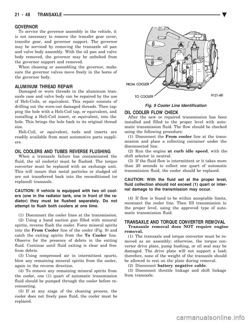
into the From Cooler line of the cooler (Fig. 9) and
catch the exiting spirits from the To Coolerline.
Observe for the presence of debris in the exiting
fluid. Continue until fluid exiting is clear and free
from debris. (3) Using compressed air in intermittent spurts,
blow any remaining mineral spirits from the cooler,
again in the reverse direction. (4) To remove any remaining mineral spirits from
the cooler, one (1) quart of automatic transmission
fluid should be pumped through the cooler before re-
connecting. (5) If at any stage of the cleaning process, the
cooler does not freely pass fluid, the cooler must be
replaced.
OIL COOLER FLOW CHECK
After the new or repaired transmission has been
installed and filled to the proper level with auto-
matic transmission fluid. The flow should be checked
using the following procedure: (1) Disconnect the From coolerline at the trans-
mission and place a collecting container under the
disconnected line. (2) Run the engine at curb idle speed , with the
shift selector in neutral. (3) If the fluid flow is intermittent or it takes more
than 20 seconds to collect one quart of automatic
transmission fluid, the cooler should be replaced.
CAUTION: With the fluid set at the proper level,
fluid collection should not exceed (1) quart or inter-
nal damage to the transmission may occur.
(4) If flow is found to be within acceptable limits,
reconnect the cooler line. Then fill transmission to
the proper level, using the approved type of auto-
matic transmission fluid.
TRANSAXLE AND TORQUE CONVERTER REMOVAL
Transaxle removal does NOT require engine
removal. (1) The transaxle and torque converter must be re-
moved as an assembly; otherwise, the torque con-
verter drive plate, pump bushing, or oil seal may be
damaged. The drive plate will not support a load;
therefore, none of the weight of the transaxle should
be allowed to rest on the plate during removal. (2) Disconnect battery negative cable .
(3) Disconnect throttle linkage and shift linkage
from transaxle.
Fig. 9 Cooler Line Identification
21 - 48 TRANSAXLE Ä
Page 2053 of 2438
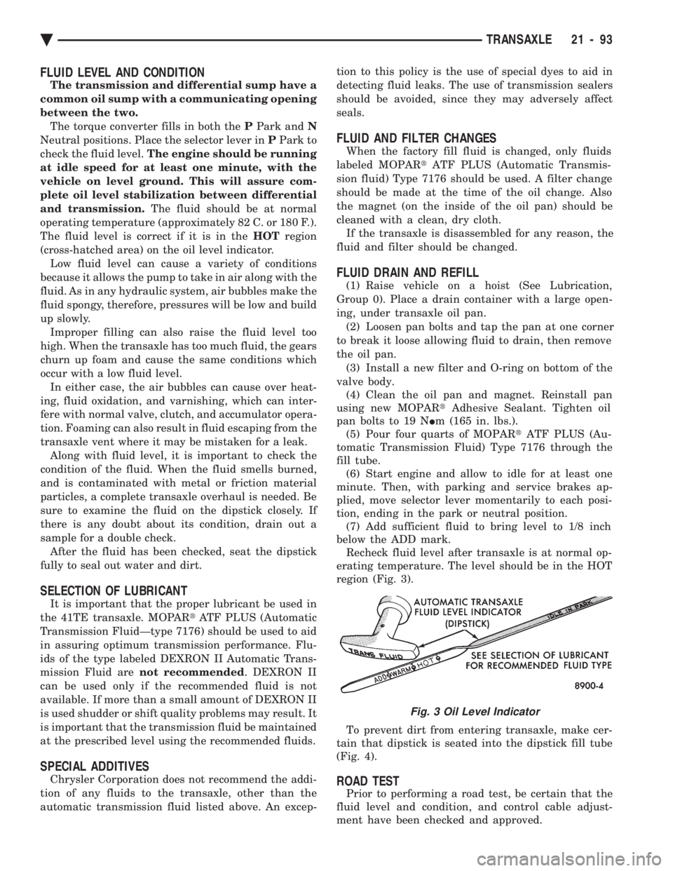
FLUID LEVEL AND CONDITION
The transmission and differential sump have a
common oil sump with a communicating opening
between the two. The torque converter fills in both the PPark and N
Neutral positions. Place the selector lever in PPark to
check the fluid level. The engine should be running
at idle speed for at least one minute, with the
vehicle on level ground. This will assure com-
plete oil level stabilization between differential
and transmission. The fluid should be at normal
operating temperature (approximately 82 C. or 180 F.).
The fluid level is correct if it is in the HOTregion
(cross-hatched area) on the oil level indicator. Low fluid level can cause a variety of conditions
because it allows the pump to take in air along with the
fluid. As in any hydraulic system, air bubbles make the
fluid spongy, therefore, pressures will be low and build
up slowly. Improper filling can also raise the fluid level too
high. When the transaxle has too much fluid, the gears
churn up foam and cause the same conditions which
occur with a low fluid level. In either case, the air bubbles can cause over heat-
ing, fluid oxidation, and varnishing, which can inter-
fere with normal valve, clutch, and accumulator opera-
tion. Foaming can also result in fluid escaping from the
transaxle vent where it may be mistaken for a leak. Along with fluid level, it is important to check the
condition of the fluid. When the fluid smells burned,
and is contaminated with metal or friction material
particles, a complete transaxle overhaul is needed. Be
sure to examine the fluid on the dipstick closely. If
there is any doubt about its condition, drain out a
sample for a double check. After the fluid has been checked, seat the dipstick
fully to seal out water and dirt.
SELECTION OF LUBRICANT
It is important that the proper lubricant be used in
the 41TE transaxle. MOPAR tATF PLUS (Automatic
Transmission FluidÐtype 7176) should be used to aid
in assuring optimum transmission performance. Flu-
ids of the type labeled DEXRON II Automatic Trans-
mission Fluid are not recommended . DEXRON II
can be used only if the recommended fluid is not
available. If more than a small amount of DEXRON II
is used shudder or shift quality problems may result. It
is important that the transmission fluid be maintained
at the prescribed level using the recommended fluids.
SPECIAL ADDITIVES
Chrysler Corporation does not recommend the addi-
tion of any fluids to the transaxle, other than the
automatic transmission fluid listed above. An excep- tion to this policy is the use of special dyes to aid in
detecting fluid leaks. The use of transmission sealers
should be avoided, since they may adversely affect
seals.
FLUID AND FILTER CHANGES
When the factory fill fluid is changed, only fluids
labeled MOPAR tATF PLUS (Automatic Transmis-
sion fluid) Type 7176 should be used. A filter change
should be made at the time of the oil change. Also
the magnet (on the inside of the oil pan) should be
cleaned with a clean, dry cloth. If the transaxle is disassembled for any reason, the
fluid and filter should be changed.
FLUID DRAIN AND REFILL
(1) Raise vehicle on a hoist (See Lubrication,
Group 0). Place a drain container with a large open-
ing, under transaxle oil pan. (2) Loosen pan bolts and tap the pan at one corner
to break it loose allowing fluid to drain, then remove
the oil pan. (3) Install a new filter and O-ring on bottom of the
valve body. (4) Clean the oil pan and magnet. Reinstall pan
using new MOPAR tAdhesive Sealant. Tighten oil
pan bolts to 19 N Im (165 in. lbs.).
(5) Pour four quarts of MOPAR tATF PLUS (Au-
tomatic Transmission Fluid) Type 7176 through the
fill tube. (6) Start engine and allow to idle for at least one
minute. Then, with parking and service brakes ap-
plied, move selector lever momentarily to each posi-
tion, ending in the park or neutral position. (7) Add sufficient fluid to bring level to 1/8 inch
below the ADD mark. Recheck fluid level after transaxle is at normal op-
erating temperature. The level should be in the HOT
region (Fig. 3).
To prevent dirt from entering transaxle, make cer-
tain that dipstick is seated into the dipstick fill tube
(Fig. 4).
ROAD TEST
Prior to performing a road test, be certain that the
fluid level and condition, and control cable adjust-
ment have been checked and approved.
Fig. 3 Oil Level Indicator
Ä TRANSAXLE 21 - 93
Page 2060 of 2438
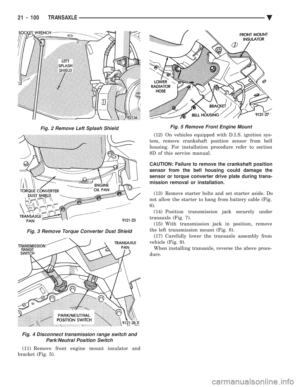
(11) Remove front engine mount insulator and
bracket (Fig. 5). (12) On vehicles equipped with D.I.S. ignition sys-
tem, remove crankshaft position sensor from bell
housing. For installation procedure refer to section
8D of this service manual.
CAUTION: Failure to remove the crankshaft position
sensor from the bell housing could damage the
sensor or torque converter drive plate during trans-
mission removal or installation.
(13) Remove starter bolts and set starter aside. Do
not allow the starter to hang from battery cable (Fig.
6). (14) Position transmission jack securely under
transaxle (Fig. 7). (15) With transmission jack in position, remove
the left transmission mount (Fig. 8). (17) Carefully lower the transaxle assembly from
vehicle (Fig. 9). When installing transaxle, reverse the above proce-
dure.
Fig. 2 Remove Left Splash Shield
Fig. 3 Remove Torque Converter Dust Shield
Fig. 4 Disconnect transmission range switch and Park/Neutral Position Switch
Fig. 5 Remove Front Engine Mount
21 - 100 TRANSAXLE Ä
Page 2064 of 2438
(7) Press the number 5 on the DRB II scan tool
key pad (Adjustments). (8) Press the number 3 on the DRB II scan tool
key pad (Quick Learn). Then follow the instructions
on the DRB II scan tool screen.
PINION FACTOR PROCEDURE
The vehicle speed readings for the speedometer are
taken from the output speed sensor. Because of dif-
ferent tire sizes and final drive ratios, the transmis-
sion control module must be calibrated to reflect the
different combinations of equipment. A procedure has
been developed called Pinion Factor. It allows the
technician to set the transmission control module ini-
tial setting so that the speedometer readings will be
correct. Failure to perform this procedure will cause a ``No
Speedometer Operation'' condition. This procedure must be performed if the transmis-
sion control module has been replaced. To properly read or reset the Pinion Factor, it is
necessary to use a DRB II scan tool. Perform the fol-
lowing steps with the DRB II scan tool to read or re-
set the Pinion Factor: (1) Plug the DRB II scan tool into the blue CCD
Bus connector. The connector is located under the in-
strument panel on the drivers side of the vehicle. (2) Insert the 1993 DRB II scan tool cartridge into
the DRB II scan tool. (3) The red and green lights on the DRB II scan
tool will light up and then begin flashing. Wait until
the lights stop flashing before continuing with this
procedure. (4) Press the number 4 key (Select System) on the
DRB II scan tool key pad. Item number 4 will not ap-
pear on the DRB II scan tool screen unless you scroll
down. It is not necessary to scroll down to be able to
choose item 4. (5) Press the number 2 on the DRB II scan tool
key pad (Transmission). (6) Press the number 1 on the DRB II scan tool
key pad. Wait for the DRB II scan tool to perform the
following three tests before continuing (These tests
are done automatically by the DRB II scan tool).
² Bus Test
² Initialize
² Transmission Control Module Part Number
(7) Press the number 5 on the DRB II scan tool
key pad (Adjustments). (8) Press the number 2 on the DRB II scan tool
key pad (Pinion Factor). Then follow the instructions
on the DRB II scan tool screen.
TORQUE CONVERTER CLUTCH BREAK-IN
PROCEDURE
A torque converter clutch break-in program is be-
ing used on all models with a 41TE. This program
will properly condition the torque converter clutch. This will eliminate shudder during partial torque
converter clutch operation on a new torque converter.
If the torque converter is replaced, the new clutch
within the torque converter will require break-in.
The current break-in status stored in the transmis-
sion control module will have to be reset to the start
of break-in with the DRB II scan tool. If a new transmission control module is put on the
vehicle, the status will be at the start of break-in.
This status is acceptable regardless of the mileage on
the torque converter. No modification of the break-in
status is required. To properly service these vehicles, it is necessary to
use a DRB II scan tool to read or reset the break-in
status. Perform the following steps with the DRB II
scan tool to reset the break-in status: (1) Plug the DRB II scan tool into the blue CCD
Bus connector. The connector is located under the in-
strument panel on the drivers side of the vehicle. (2) Insert the 1993 DRB II scan tool cartridge into
the DRB II scan tool. (3) The red and green lights on the DRB II scan
tool will light up and then begin flashing. Wait until
the lights stop flashing before continuing with this
procedure. (4) Press the number 4 key (Select System) on the
DRB II scan tool key pad. Item number 4 will not ap-
pear on the DRB II scan tool screen unless you scroll
down. It is not necessary to scroll down to be able to
choose item 4. (5) Press the number 2 on the DRB II scan tool
key pad (Transmission). (6) Press the number 1 on the DRB II scan tool
key pad. Wait for the DRB II scan tool to perform the
following three tests before continuing (These tests
are done automatically by the DRB II scan tool).
² Bus Test
² Initialize
² Transmission Control Module Part Number
(7) Press the number 5 on the DRB II scan tool
key pad (Adjustments). (8) Press the number 1 on the DRB II scan tool
key pad (Reset LU Clutch). The DRB II scan tool will
display one of three screens. (a) LU Clutch Break-in Status: Start
(b) LU Clutch Break-in Status: In-progress
Press ENTER to Reset Break-in status (c) LU Clutch Break-in Status: CompletePress
ENTER to Reset Break-in status
If screen (a) appears, the transmission control mod-
ule is at the beginning of its break-in program. No
further action is required. If screen (b) appears, the transmission control mod-
ule is in the middle of a its break-in program. Press
the enter key on the DRB II scan tool key pad to re-
turn the status to the start of break-in.
21 - 104 TRANSAXLE Ä
Page 2106 of 2438
² Park
² Neutral
² Reverse
² Second Gear
No upshifts or downshifts are allowed while in the
Limp-in mode. The position of the manual valve
alone allows the three ranges that are available. Although engine performance will be reduced while
in this mode, the vehicle can be driven in for service.
DRB II SCAN TOOL
The DRB II scan tool is a diagnostic read-out box
designed by Chrysler to gain access to the on-board
diagnostics. These on-board diagnostics are found on
all Chrysler-built cars and trucks. The DRB II scan tool has a few diagnostic capabil-
ities by itself. To perform most diagnostic tests, a
program cartridge must be inserted. It contains the
diagnostic test programs. There are scan tools available from other manufac-
tures that can be used on Chrysler vehicles. How-
ever, the diagnostic test procedures in this manual
have been designed for use with the Chrysler's DRB
II scan tool. The DRB II scan tool operates by communicating
with the module of the vehicle system being tested.
To communicate with the transmission control mod-
ule, the DRB II scan tool must be connected to the blue CCD bus connector located under the instru-
ment panel. Refer to the ``Using the DRB II Scan
Tool'' manual or the Diagnostic Procedures Manual
for information on how to use the DRB II scan tool.
DIAGNOSTIC TROUBLE CODE CHARTS
Below is a brief description of what each section of
the diagnostic trouble code charts are addressing.
² DIAGNOSTIC TROUBLE CODE- Tells the code
number and name (as shown on the DRB II scan
tool).
² BACKGROUND- A brief description of the circuit
that the transmission control module is monitoring.
² WHEN CHECKED- The point of time or condition
when the transmission control module makes it's sys-
tem check.
² ARMING CONDITIONS- The parameters that
must be met before a code can be set.
² FAULT CONDITION- What the transmission con-
trol module saw that is determined to be a problem.
(ie. voltage to high or low, switch/solenoid problems)
² FAULT SET TIME- Refers to the amount of time
(in seconds) a failure must occur before a diagnostic
trouble code is set in memory.
² EFFECT- Refers to how the fault effects transaxle
operations.
² POSSIBLE CAUSE- Refers to the systems or cir-
cuits which could cause the fault to be recorded.
21 - 146 TRANSAXLE Ä