1993 CHEVROLET DYNASTY oil
[x] Cancel search: oilPage 1625 of 2438
OIL PUMP REMOVAL
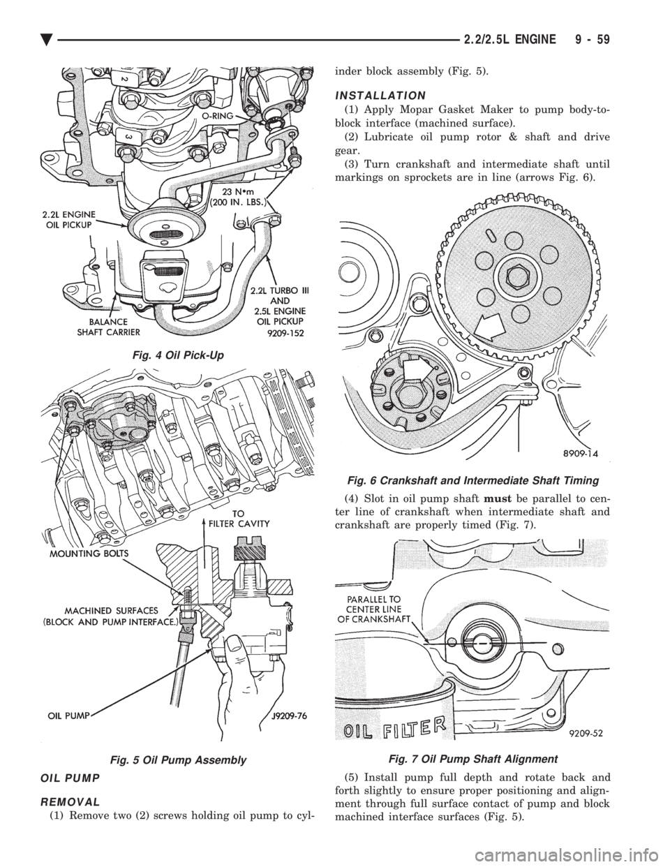
(1) Remove two (2) screws holding oil pump to cyl- inder block assembly (Fig. 5).
INSTALLATION
(1) Apply Mopar Gasket Maker to pump body-to-
block interface (machined surface). (2) Lubricate oil pump rotor & shaft and drive
gear. (3) Turn crankshaft and intermediate shaft until
markings on sprockets are in line (arrows Fig. 6).
(4) Slot in oil pump shaft mustbe parallel to cen-
ter line of crankshaft when intermediate shaft and
crankshaft are properly timed (Fig. 7).
(5) Install pump full depth and rotate back and
forth slightly to ensure proper positioning and align-
ment through full surface contact of pump and block
machined interface surfaces (Fig. 5).
Fig. 4 Oil Pick-Up
Fig. 5 Oil Pump Assembly
Fig. 6 Crankshaft and Intermediate Shaft Timing
Fig. 7 Oil Pump Shaft Alignment
Ä 2.2/2.5L ENGINE 9 - 59
Page 1626 of 2438
CAUTION: Pump must be held in fully seated posi-
tion (described above) while installing screws. (6) Tighten screws to 23 N Im (200 in. lbs.).
INSPECTION
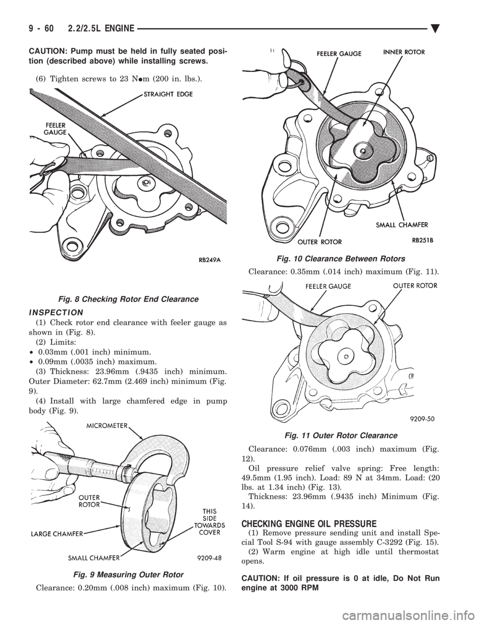
(1) Check rotor end clearance with feeler gauge as
shown in (Fig. 8). (2) Limits:
² 0.03mm (.001 inch) minimum.
² 0.09mm (.0035 inch) maximum.
(3) Thickness: 23.96mm (.9435 inch) minimum.
Outer Diameter: 62.7mm (2.469 inch) minimum (Fig.
9). (4) Install with large chamfered edge in pump
body (Fig. 9).
Clearance: 0.20mm (.008 inch) maximum (Fig. 10). Clearance: 0.35mm (.014 inch) maximum (Fig. 11).
Clearance: 0.076mm (.003 inch) maximum (Fig.
12). Oil pressure relief valve spring: Free length:
49.5mm (1.95 inch). Load: 89 N at 34mm. Load: (20
lbs. at 1.34 inch) (Fig. 13). Thickness: 23.96mm (.9435 inch) Minimum (Fig.
14).
CHECKING ENGINE OIL PRESSURE
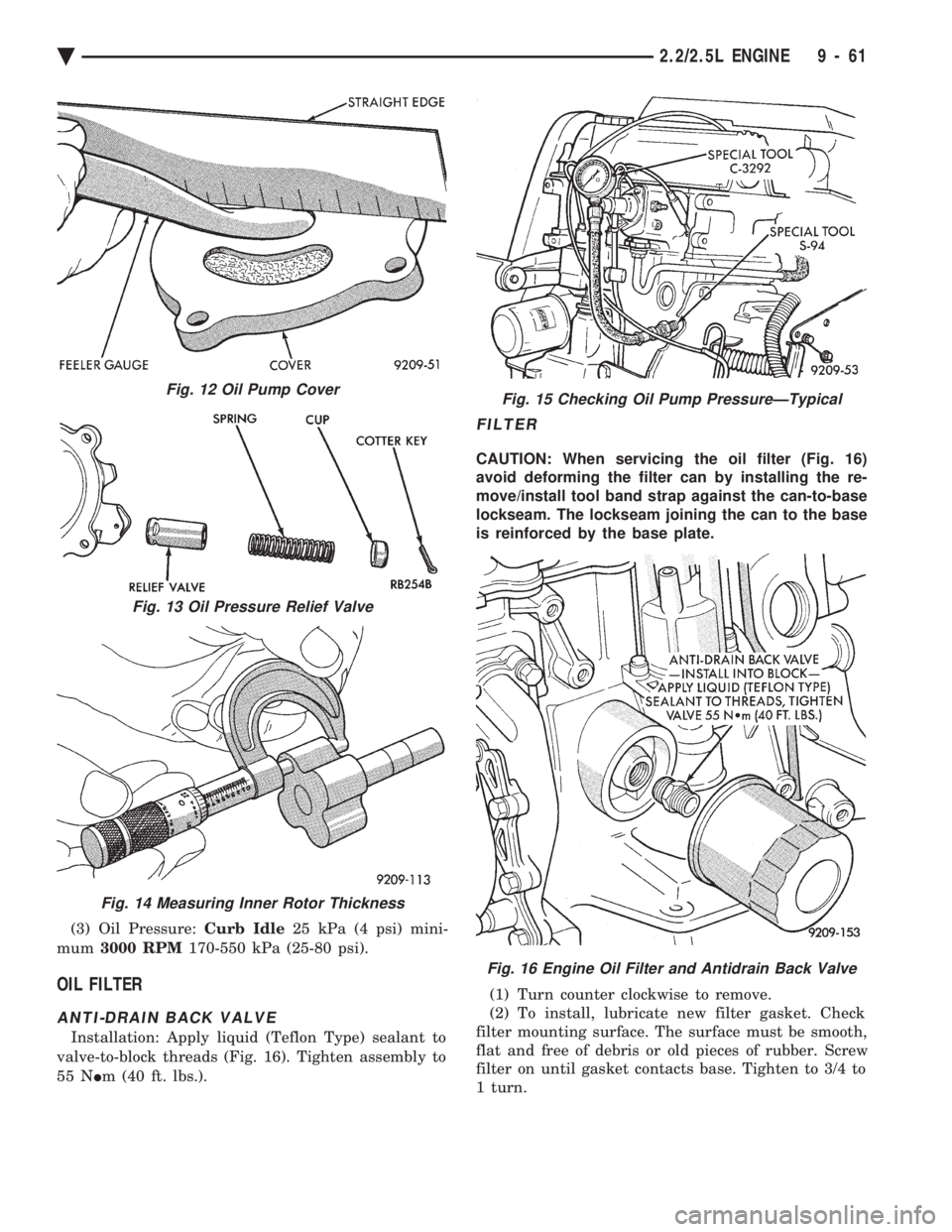
(1) Remove pressure sending unit and install Spe-
cial Tool S-94 with gauge assembly C-3292 (Fig. 15). (2) Warm engine at high idle until thermostat
opens.
CAUTION: If oil pressure is 0 at idle, Do Not Run
engine at 3000 RPM
Fig. 8 Checking Rotor End Clearance
Fig. 9 Measuring Outer Rotor
Fig. 10 Clearance Between Rotors
Fig. 11 Outer Rotor Clearance
9 - 60 2.2/2.5L ENGINE Ä
Page 1627 of 2438
(3) Oil Pressure: Curb Idle25 kPa (4 psi) mini-
mum 3000 RPM 170-550 kPa (25-80 psi).
OIL FILTER
ANTI-DRAIN BACK VALVE
Installation: Apply liquid (Teflon Type) sealant to
valve-to-block threads (Fig. 16). Tighten assembly to
55 N Im (40 ft. lbs.).
FILTER
CAUTION: When servicing the oil filter (Fig. 16)
avoid deforming the filter can by installing the re-
move/install tool band strap against the can-to-base
lockseam. The lockseam joining the can to the base
is reinforced by the base plate.
(1) Turn counter clockwise to remove.
(2) To install, lubricate new filter gasket. Check
filter mounting surface. The surface must be smooth,
flat and free of debris or old pieces of rubber. Screw
filter on until gasket contacts base. Tighten to 3/4 to
1 turn.
Fig. 12 Oil Pump Cover
Fig. 13 Oil Pressure Relief Valve
Fig. 14 Measuring Inner Rotor Thickness
Fig. 15 Checking Oil Pump PressureÐTypical
Fig. 16 Engine Oil Filter and Antidrain Back Valve
Ä 2.2/2.5L ENGINE 9 - 61
Page 1632 of 2438
3.0L ENGINE INDEX
page page
Accessory Drive Belt Service ................ 70
Auto Lash Adjuster ....................... 75
Camshaft Service ........................ 76
Checking Engine Oil Pressure ............... 93
Crankshaft and Cylinder Block, Assembly Service . 86
Cylinder Block ........................... 89
Cylinder Head ........................... 78
Cylinder Head and Camshaft Service ......... 75
Engine Assembly ......................... 69
Engine Lubrication System ................. 91
Engine Mounts .......................... 68 Engine Specifications
..................... 95
General Information ....................... 66
Oil Filter and Bracket ..................... 94
Oil Pan ................................ 92
Oil Pump Service ........................ 92
Piston and Connecting Rod Assembly Service . . . 82
Timing Belt InspectionÐIn Vehicle ............ 72
Timing Belt Service ....................... 72
Valve Service ........................... 80
GENERAL INFORMATION
ENGINE IDENTIFICATION NUMBER OR CODE
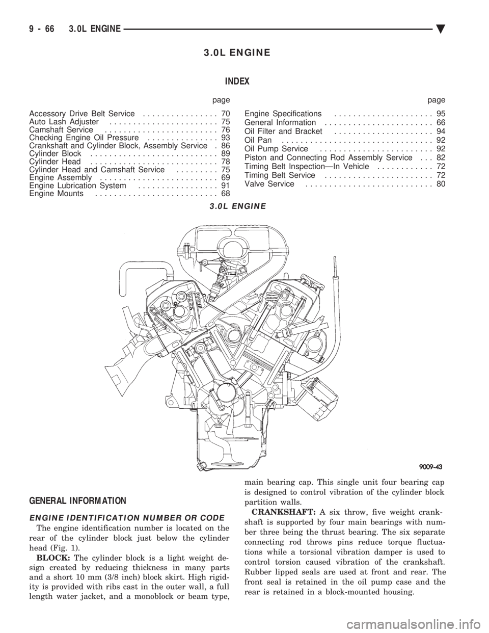
The engine identification number is located on the
rear of the cylinder block just below the cylinder
head (Fig. 1). BLOCK: The cylinder block is a light weight de-
sign created by reducing thickness in many parts
and a short 10 mm (3/8 inch) block skirt. High rigid-
ity is provided with ribs cast in the outer wall, a full
length water jacket, and a monoblock or beam type, main bearing cap. This single unit four bearing cap
is designed to control vibration of the cylinder block
partition walls.
CRANKSHAFT: A six throw, five weight crank-
shaft is supported by four main bearings with num-
ber three being the thrust bearing. The six separate
connecting rod throws pins reduce torque fluctua-
tions while a torsional vibration damper is used to
control torsion caused vibration of the crankshaft.
Rubber lipped seals are used at front and rear. The
front seal is retained in the oil pump case and the
rear is retained in a block-mounted housing.
3.0L ENGINE
9 - 66 3.0L ENGINE Ä
Page 1633 of 2438
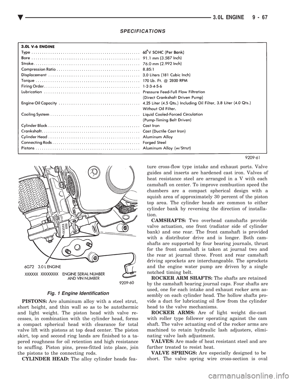
PISTONS: Are aluminum alloy with a steel strut,
short height, and thin wall so as to be autothermic
and light weight. The piston head with valve re-
cesses, in combination with the cylinder head, forms
a compact spherical head with clearance for total
valve lift with pistons at top dead center. The piston
skirt, top and second ring lands are finished to a ta-
pered roughness for oil retention and high resistance
to scuffing. Piston pins, press-fitted into place, join
the pistons to the connecting rods. CYLINDER HEAD: The alloy cylinder heads fea- ture cross-flow type intake and exhaust ports. Valve
guides and inserts are hardened cast iron. Valves of
heat resistance steel are arranged i
n a V with each
camshaft on center. To improve combustion speed the
chambers are a compact spherical design with a
squish area of approximately 30 percent of the piston
top area. The cylinder heads are common to either
cylinder bank by reversing the direction of installa-
tion. CAMSHAFTS: Two overhead camshafts provide
valve actuation, one front (radiator side of cylinder
bank) and one rear. The front camshaft is provided
with a distributor drive and is longer. Both cam-
shafts are supported by four bearing journals, thrust
for the front camshaft is taken at journal two and
the rear at journal three. Front and rear camshaft
driving sprockets are interchangeable. The sprockets
and the engine water pump are driven by a single
notched timing belt. ROCKER ARM SHAFTS: The shafts are retained
by the camshaft bearing journal caps. Four shafts are
used, one for each intake and exhaust rocker arm as-
sembly on each cylinder head. The hollow shafts pro-
vide a duct for lubricating oil flow from the cylinder
head to the valve mechanisms. ROCKER ARMS: Are of light weight die-cast
with roller type follower operating against the cam
shaft. The valve actuating end of the rocker arms are
machined to retain hydraulic lash adjusters, elimi-
nating valve lash adjustment. VALVES: Are made of heat resistant steel and are
further treated to resist heat. VALVE SPRINGS: Are especially designed to be
short. The valve spring wire cross-section is oval
SPECIFICATIONS
Fig. 1 Engine Identification
Ä 3.0L ENGINE 9 - 67
Page 1634 of 2438
shaped and provides the same spring tension as
longer springs. Valve spring retainers, locks and
seals are conventional.INTAKE MANIFOLD: The aluminum alloy man-
ifold is a cross type with long runners to improve in-
ertia. The runners, attaching below at the cylinder
head, also attach above and support an air plenum.
The air plenum chamber absorbs air pulsations cre-
ated during the suction phase of each cylinder. EXHAUST MANIFOLDS: Both manifolds are a
log style made of ductile cast iron. Exhaust gasses,
collected from the front cylinder bank, leave the
front manifold through an end outlet and are fed
through an upper crossover tube to the rear mani-
fold. The collected exhaust from both manifolds are
combined, and exit to the exhaust pipe through an
articulated joint. ENGINE LUBRICATION: System is a full flow
filtration, pressure feed type. The oil pump is
mounted in the chaincase cover. The pump inner ro-
tor is driven by the crankshaft. The engine oil pan
contains a baffle plate to control oil level fluctuation
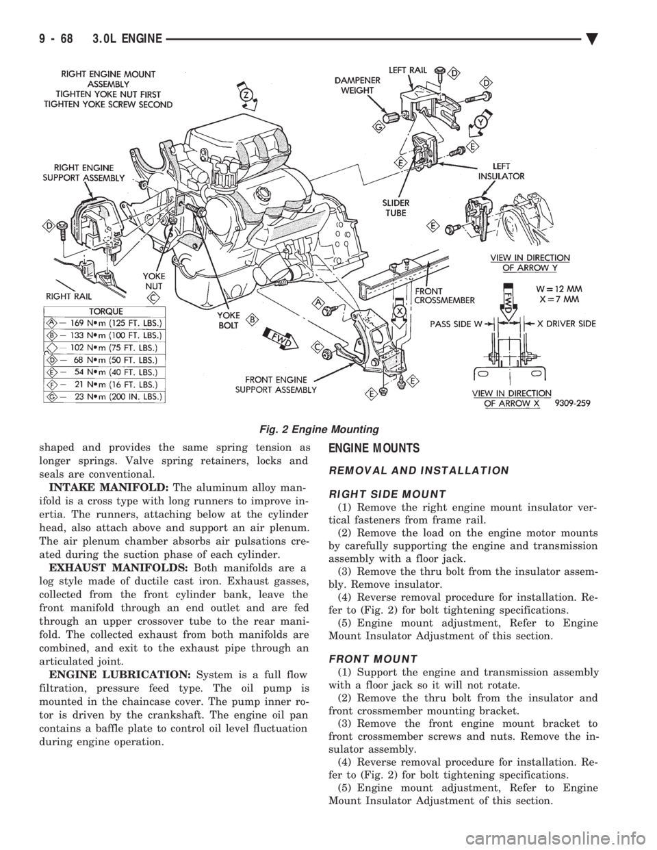
during engine operation.ENGINE MOUNTS
REMOVAL AND INSTALLATION
RIGHT SIDE MOUNT
(1) Remove the right engine mount insulator ver-
tical fasteners from frame rail. (2) Remove the load on the engine motor mounts
by carefully supporting the engine and transmission
assembly with a floor jack. (3) Remove the thru bolt from the insulator assem-
bly. Remove insulator. (4) Reverse removal procedure for installation. Re-
fer to (Fig. 2) for bolt tightening specifications. (5) Engine mount adjustment, Refer to Engine
Mount Insulator Adjustment of this section.
FRONT MOUNT
(1) Support the engine and transmission assembly
with a floor jack so it will not rotate. (2) Remove the thru bolt from the insulator and
front crossmember mounting bracket. (3) Remove the front engine mount bracket to
front crossmember screws and nuts. Remove the in-
sulator assembly. (4) Reverse removal procedure for installation. Re-
fer to (Fig. 2) for bolt tightening specifications. (5) Engine mount adjustment, Refer to Engine
Mount Insulator Adjustment of this section.
Fig. 2 Engine Mounting
9 - 68 3.0L ENGINE Ä
Page 1635 of 2438
LEFT SIDE MOUNT
(1) Raise vehicle on hoist and remove left front
wheel. (2) Remove inter splash shield.
(3) Support the transmission with a transmission
jack. (4) Remove the insulator thru bolt from the mount.
(5) Remove the transmission mount fasteners and
remove mount. (6) Reverse removal procedure for installation. En-
sure that the slide tube is seated into the rail
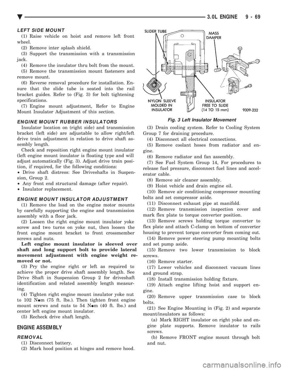
bracket guides. Refer to (Fig. 3) for bolt tightening
specifications. (7) Engine mount adjustment, Refer to Engine
Mount Insulator Adjustment of this section.
ENGINE MOUNT RUBBER INSULATORS
Insulator location on (right side) and transmission
bracket (left side) are adjustable to allow right/left
drive train adjustment in relation to drive shaft as-
sembly length. Check and reposition right engine mount insulator
(left engine mount insulator is floating type and will
adjust automatically (Fig. 3). Adjust drive train posi-
tion, if required, for the following conditions:
² Drive shaft distress: See Driveshafts in Suspen-
sion, Group 2.
² Any front end structural damage (after repair).
² Insulator replacement.
ENGINE MOUNT INSULATOR ADJUSTMENT
(1) Remove the load on the engine motor mounts
by carefully supporting the engine and transmission
assembly with a floor jack. (2) Loosen the right engine mount insulator yoke
screw and two turns on yoke nut, then loosen the
front engine mount bracket to front crossmember
screws and nuts. Left engine mount insulator is sleeved over
shaft and long support bolt to provide lateral
movement adjustment with engine weight re-
moved or not. (3) Pry the engine right or left as required to
achieve the proper drive shaft assembly length. See
Drive Shaft in Suspension Group 2 for driveshaft
identification and related assembly length measur-
ing. (4) Tighten right engine mount insulator yoke nut
to 102 N Im (75 ft. lbs.). Then tighten front engine
mount screws and nuts to 54 N Im (40 ft. lbs.) and
center left engine mount insulator. (5) Recheck drive shaft length.
ENGINE ASSEMBLY
REMOVAL
(1) Disconnect battery.
(2) Mark hood position at hinges and remove hood. (3) Drain cooling system. Refer to Cooling System
Group 7 for draining procedure. (4) Disconnect all electrical connections.
(5) Remove coolant hoses from radiator and en-
gine. (6) Remove radiator and fan assembly.
(7) See Fuel System Group 14, For procedures to
release fuel pressure, disconnect fuel lines and accel-
erator cable. (8) Remove air cleaner assembly.
(9) Hoist vehicle and drain engine oil.
(10) Remove air conditioning compressor mounting
bolts and set compressor aside. (11) Disconnect exhaust pipe at manifold.
(12) Remove transmission inspection cover and
mark flex plate to torque converter position. (13) Remove screws holding torque converter to
flex plate and attach C-clamp on bottom of converter
housing to prevent torque converter from coming out. (14) Remove power steering pump mounting bolts
and set pump aside. (15) Remove two lower transmission to block
screws. (16) Remove starter.
(17) Lower vehicles and disconnect vacuum lines
and ground strap. (18) Install transmission holding fixture.
(19) Attach engine lifting hoist and support en-
gine. (20) Remove upper transmission case to block
bolts. (21) See Engine Mounting in (Fig. 2) and separate
mount/insulators as follows: (a) Mark RIGHT insulator on right yoke and en-
gine plate supports. Remove insulator to rails
screws. (b) Remove FRONT engine mount through bolt
and nut.
Fig. 3 Left Insulator Movement
Ä 3.0L ENGINE 9 - 69
Page 1636 of 2438
(c) Remove LEFT insulator through bolt from in-
side wheelhouse or insulator bracket to transmis-
sion screws.
(22) Remove engine.
INSTALLATION
(1) Attach hoist and lower engine into engine com-
partment. (2) Align engine mounts and install but do not
tighten until all mounting bolts have been installed.
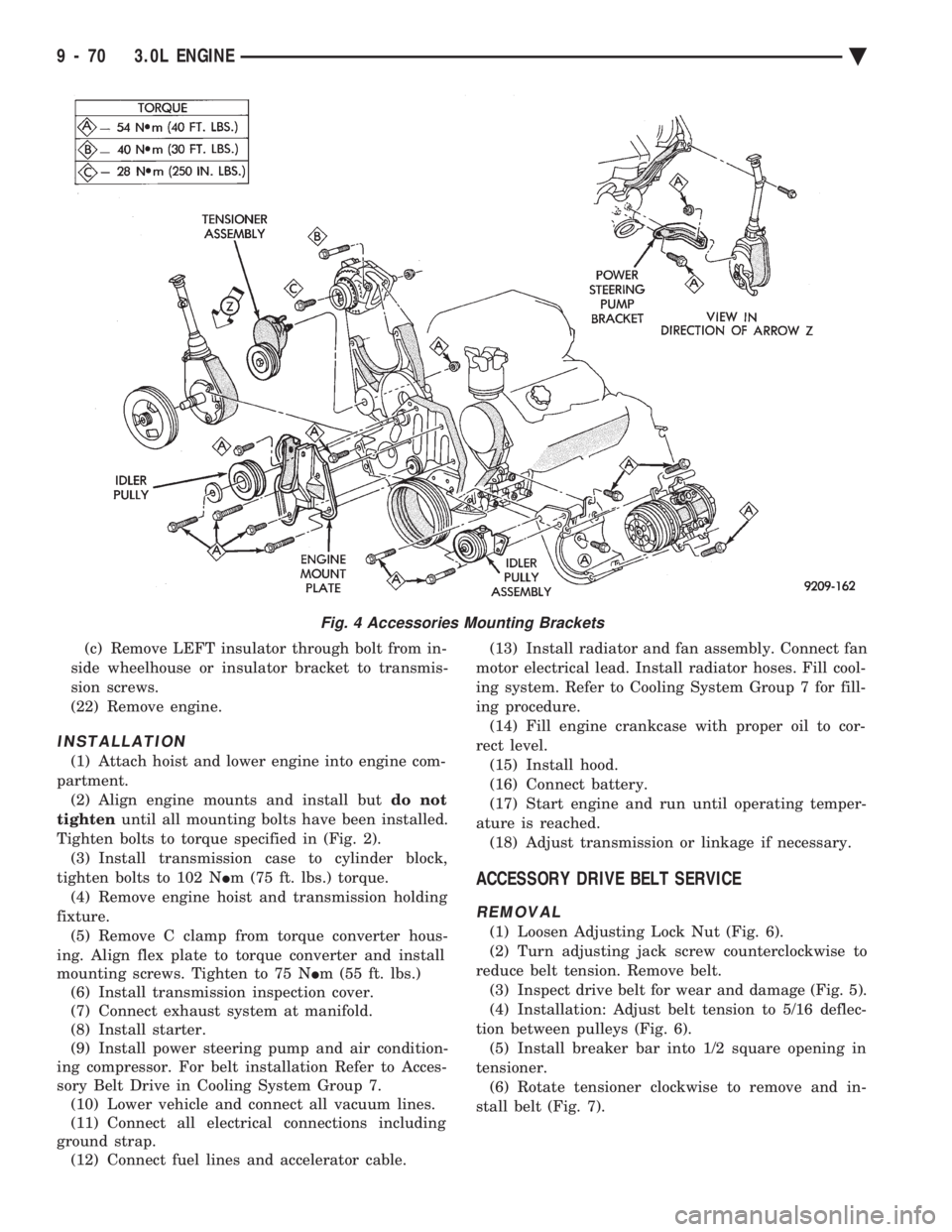
Tighten bolts to torque specified in (Fig. 2). (3) Install transmission case to cylinder block,
tighten bolts to 102 N Im (75 ft. lbs.) torque.
(4) Remove engine hoist and transmission holding
fixture. (5) Remove C clamp from torque converter hous-
ing. Align flex plate to torque converter and install
mounting screws. Tighten to 75 N Im (55 ft. lbs.)
(6) Install transmission inspection cover.
(7) Connect exhaust system at manifold.
(8) Install starter.
(9) Install power steering pump and air condition-
ing compressor. For belt installation Refer to Acces-
sory Belt Drive in Cooling System Group 7. (10) Lower vehicle and connect all vacuum lines.
(11) Connect all electrical connections including
ground strap. (12) Connect fuel lines and accelerator cable. (13) Install radiator and fan assembly. Connect fan
motor electrical lead. Install radiator hoses. Fill cool-
ing system. Refer to Cooling System Group 7 for fill-
ing procedure. (14) Fill engine crankcase with proper oil to cor-
rect level. (15) Install hood.
(16) Connect battery.
(17) Start engine and run until operating temper-
ature is reached. (18) Adjust transmission or linkage if necessary.
ACCESSORY DRIVE BELT SERVICE
REMOVAL
(1) Loosen Adjusting Lock Nut (Fig. 6).
(2) Turn adjusting jack screw counterclockwise to
reduce belt tension. Remove belt. (3) Inspect drive belt for wear and damage (Fig. 5).
(4) Installation: Adjust belt tension to 5/16 deflec-
tion between pulleys (Fig. 6). (5) Install breaker bar into 1/2 square opening in
tensioner. (6) Rotate tensioner clockwise to remove and in-
stall belt (Fig. 7).
Fig. 4 Accessories Mounting Brackets
9 - 70 3.0L ENGINE Ä