1993 CHEVROLET DYNASTY oil
[x] Cancel search: oilPage 1655 of 2438
(3) Apply light coating of engine oil to the entire
circumference of oil seal lip. (4) Install seal assembly on cylinder block and
tighten bolts to 12 N Im (104 in. lbs.)
FRONT CRANKSHAFT OIL PUMP AND OIL
SEAL
(1) Install oil pump gasket and oil pump case
(Figs. 1 and 14). CAUTION: Install bolts, depending on length in lo-
cations shown in (Fig. 14).
(2) Using front crankshaft oil seal installer Special
Tool MB998306 install oil seal in oil pump (Fig. 15).
CYLINDER BLOCK
Inspect cylinder block for scratches, cracks and rust
or corrosion, and repair or replace as required.
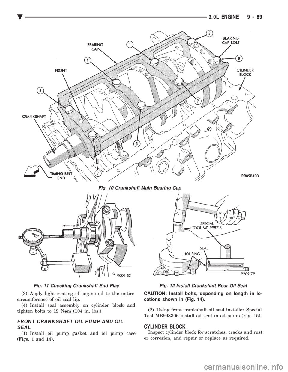
Fig. 10 Crankshaft Main Bearing Cap
Fig. 11 Checking Crankshaft End PlayFig. 12 Install Crankshaft Rear Oil Seal
Ä 3.0L ENGINE 9 - 89
Page 1656 of 2438
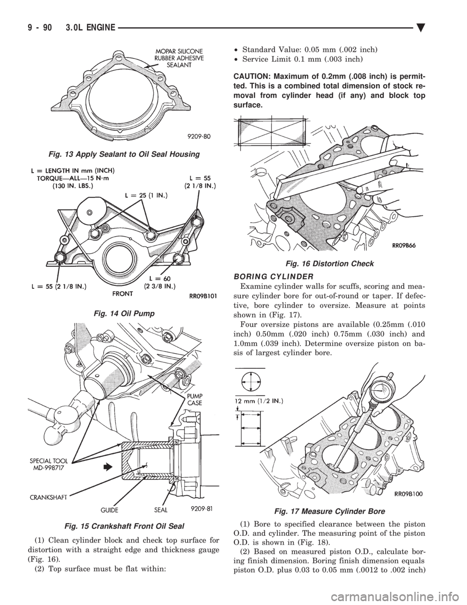
(1) Clean cylinder block and check top surface for
distortion with a straight edge and thickness gauge
(Fig. 16). (2) Top surface must be flat within: ²
Standard Value: 0.05 mm (.002 inch)
² Service Limit 0.1 mm (.003 inch)
CAUTION: Maximum of 0.2mm (.008 inch) is permit-
ted. This is a combined total dimension of stock re-
moval from cylinder head (if any) and block top
surface.
BORING CYLINDER
Examine cylinder walls for scuffs, scoring and mea-
sure cylinder bore for out-of-round or taper. If defec-
tive, bore cylinder to oversize. Measure at points
shown in (Fig. 17). Four oversize pistons are available (0.25mm (.010
inch) 0.50mm (.020 inch) 0.75mm (.030 inch) and
1.0mm (.039 inch). Determine oversize piston on ba-
sis of largest cylinder bore.
(1) Bore to specified clearance between the piston
O.D. and cylinder. The measuring point of the piston
O.D. is shown in (Fig. 18). (2) Based on measured piston O.D., calculate bor-
ing finish dimension. Boring finish dimension equals
piston O.D. plus 0.03 to 0.05 mm (.0012 to .002 inch)
Fig. 13 Apply Sealant to Oil Seal Housing
Fig. 14 Oil Pump
Fig. 15 Crankshaft Front Oil Seal
Fig. 16 Distortion Check
Fig. 17 Measure Cylinder Bore
9 - 90 3.0L ENGINE Ä
Page 1657 of 2438
(clearance between piston O.D. and cylinder) minus
0.02 mm which is the boring margin. (3) Bore all cylinders to calculated boring finish di-
mension. Then bore the final finish dimension (piston
O.D. plus cylinder clearance). (4) Check clearance between piston and cylinder,
clearance should be 0.03 to 0.05 mm (.0012 to .002
inch).
ENGINE LUBRICATION SYSTEM
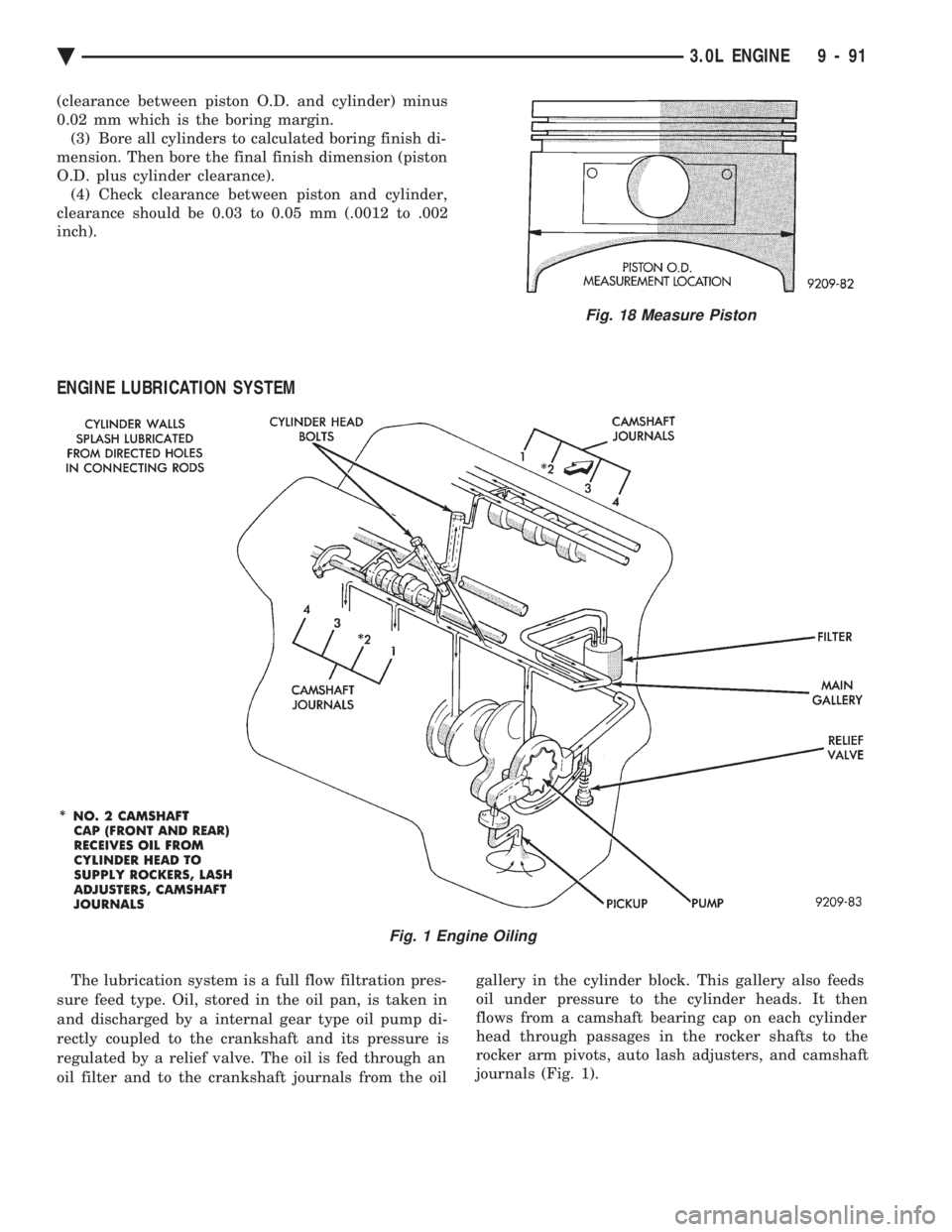
The lubrication system is a full flow filtration pres-
sure feed type. Oil, stored in the oil pan, is taken in
and discharged by a internal gear type oil pump di-
rectly coupled to the crankshaft and its pressure is
regulated by a relief valve. The oil is fed through an
oil filter and to the crankshaft journals from the oil gallery in the cylinder block. This gallery also feeds
oil under pressure to the cylinder heads. It then
flows from a camshaft bearing cap on each cylinder
head through passages in the rocker shafts to the
rocker arm pivots, auto lash adjusters, and camshaft
journals (Fig. 1).
Fig. 18 Measure Piston
Fig. 1 Engine Oiling
Ä 3.0L ENGINE 9 - 91
Page 1658 of 2438
OIL PAN
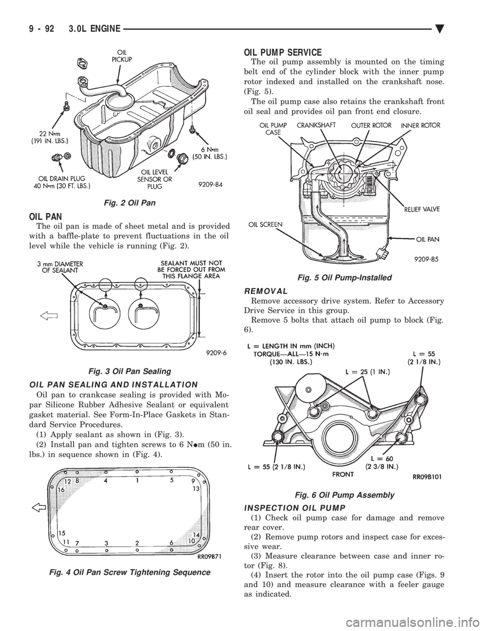
The oil pan is made of sheet metal and is provided
with a baffle-plate to prevent fluctuations in the oil
level while the vehicle is running (Fig. 2).
OIL PAN SEALING AND INSTALLATION
Oil pan to crankcase sealing is provided with Mo-
par Silicone Rubber Adhesive Sealant or equivalent
gasket material. See Form-In-Place Gaskets in Stan-
dard Service Procedures. (1) Apply sealant as shown in (Fig. 3).
(2) Install pan and tighten screws to 6 N Im (50 in.
lbs.) in sequence shown in (Fig. 4).
OIL PUMP SERVICE
The oil pump assembly is mounted on the timing
belt end of the cylinder block with the inner pump
rotor indexed and installed on the crankshaft nose.
(Fig. 5). The oil pump case also retains the crankshaft front
oil seal and provides oil pan front end closure.
REMOVAL
Remove accessory drive system. Refer to Accessory
Drive Service in this group. Remove 5 bolts that attach oil pump to block (Fig.
6).
INSPECTION OIL PUMP
(1) Check oil pump case for damage and remove
rear cover. (2) Remove pump rotors and inspect case for exces-
sive wear. (3) Measure clearance between case and inner ro-
tor (Fig. 8). (4) Insert the rotor into the oil pump case (Figs. 9
and 10) and measure clearance with a feeler gauge
as indicated.
Fig. 2 Oil Pan
Fig. 3 Oil Pan Sealing
Fig. 4 Oil Pan Screw Tightening Sequence
Fig. 5 Oil Pump-Installed
Fig. 6 Oil Pump Assembly
9 - 92 3.0L ENGINE Ä
Page 1659 of 2438
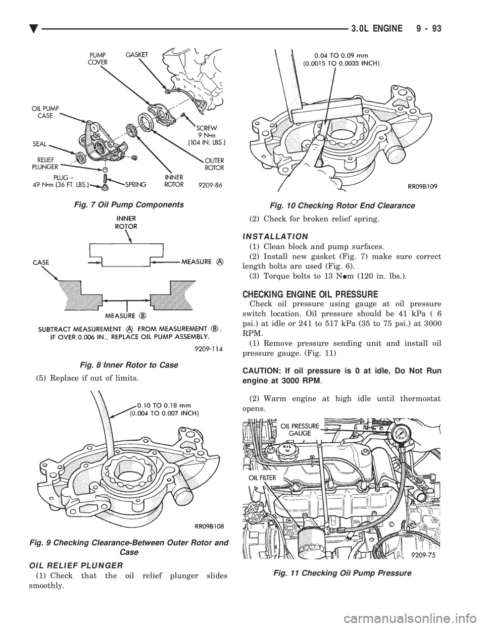
(5) Replace if out of limits.
OIL RELIEF PLUNGER
(1) Check that the oil relief plunger slides
smoothly. (2) Check for broken relief spring.
INSTALLATION
(1) Clean block and pump surfaces.
(2) Install new gasket (Fig. 7) make sure correct
length bolts are used (Fig. 6). (3) Torque bolts to 13 N Im (120 in. lbs.).
CHECKING ENGINE OIL PRESSURE
Check oil pressure using gauge at oil pressure
switch location. Oil pressure should be 41 kPa ( 6
psi.) at idle or 241 to 517 kPa (35 to 75 psi.) at 3000
RPM. (1) Remove pressure sending unit and install oil
pressure gauge. (Fig. 11)
CAUTION: If oil pressure is 0 at idle, Do Not Run
engine at 3000 RPM .
(2) Warm engine at high idle until thermostat
opens.
Fig. 7 Oil Pump Components
Fig. 8 Inner Rotor to Case
Fig. 9 Checking Clearance-Between Outer Rotor and Case
Fig. 10 Checking Rotor End Clearance
Fig. 11 Checking Oil Pump Pressure
Ä 3.0L ENGINE 9 - 93
Page 1660 of 2438
OIL FILTER AND BRACKET
BRACKET INSPECTION
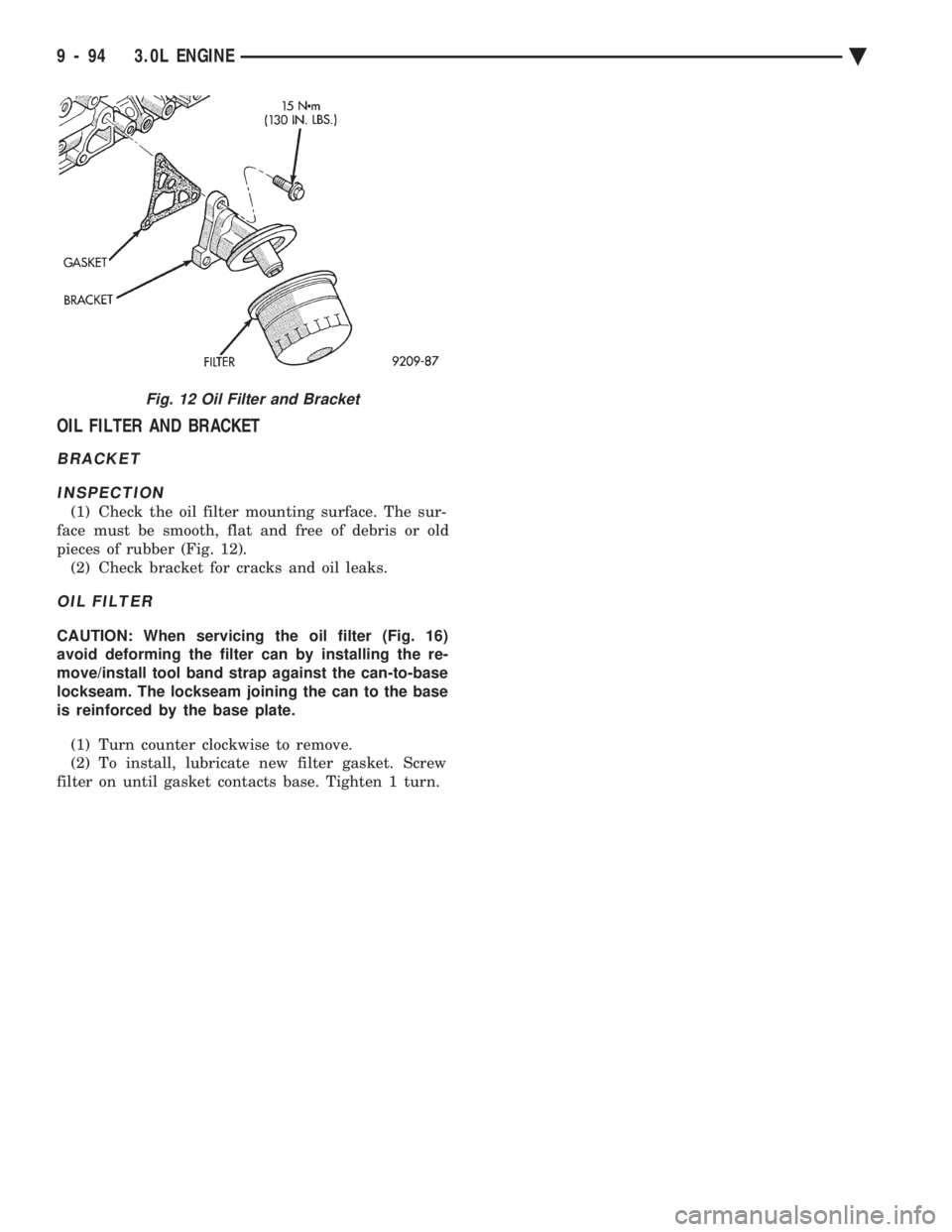
(1) Check the oil filter mounting surface. The sur-
face must be smooth, flat and free of debris or old
pieces of rubber (Fig. 12). (2) Check bracket for cracks and oil leaks.
OIL FILTER
CAUTION: When servicing the oil filter (Fig. 16)
avoid deforming the filter can by installing the re-
move/install tool band strap against the can-to-base
lockseam. The lockseam joining the can to the base
is reinforced by the base plate.
(1) Turn counter clockwise to remove.
(2) To install, lubricate new filter gasket. Screw
filter on until gasket contacts base. Tighten 1 turn.
Fig. 12 Oil Filter and Bracket
9 - 94 3.0L ENGINE Ä
Page 1664 of 2438
3.3/3.8L ENGINE INDEX
page page
Camshaft .............................. 112
Camshaft BearingsÐEngine Removed From Vehicle .............................. 113
Checking Engine Oil Pressure .............. 125
Connecting Rods ........................ 118
Crankshaft Oil Seals Service ............... 121
Crankshaft Service ...................... 118
Cylinder Block, Piston and Connecting Rod Assembly Service ...................... 114
Cylinder Heads ......................... 102
Engine Assembly ........................ 101
Engine Core Oil and Cam Plugs ............ 113
Engine Lubrication System ................ 122 Engine Mounts
.......................... 99
Engine Specifications ..................... 126
General Information ....................... 98
Hydraulic Tappets ....................... 108
Installing Piston and Connecting Rod Assembly . 117
Intake Manifold Sealing ................... 104
Oil Filter .............................. 125
Oil Pan Service ......................... 122
Oil Pump Service ....................... 123
Rocker Arms and Shaft Assembly ........... 102
Timing Chain Cover, Oil Seal and Chain ...... 109
Valve Service .......................... 104
Valve Timing ........................... 109
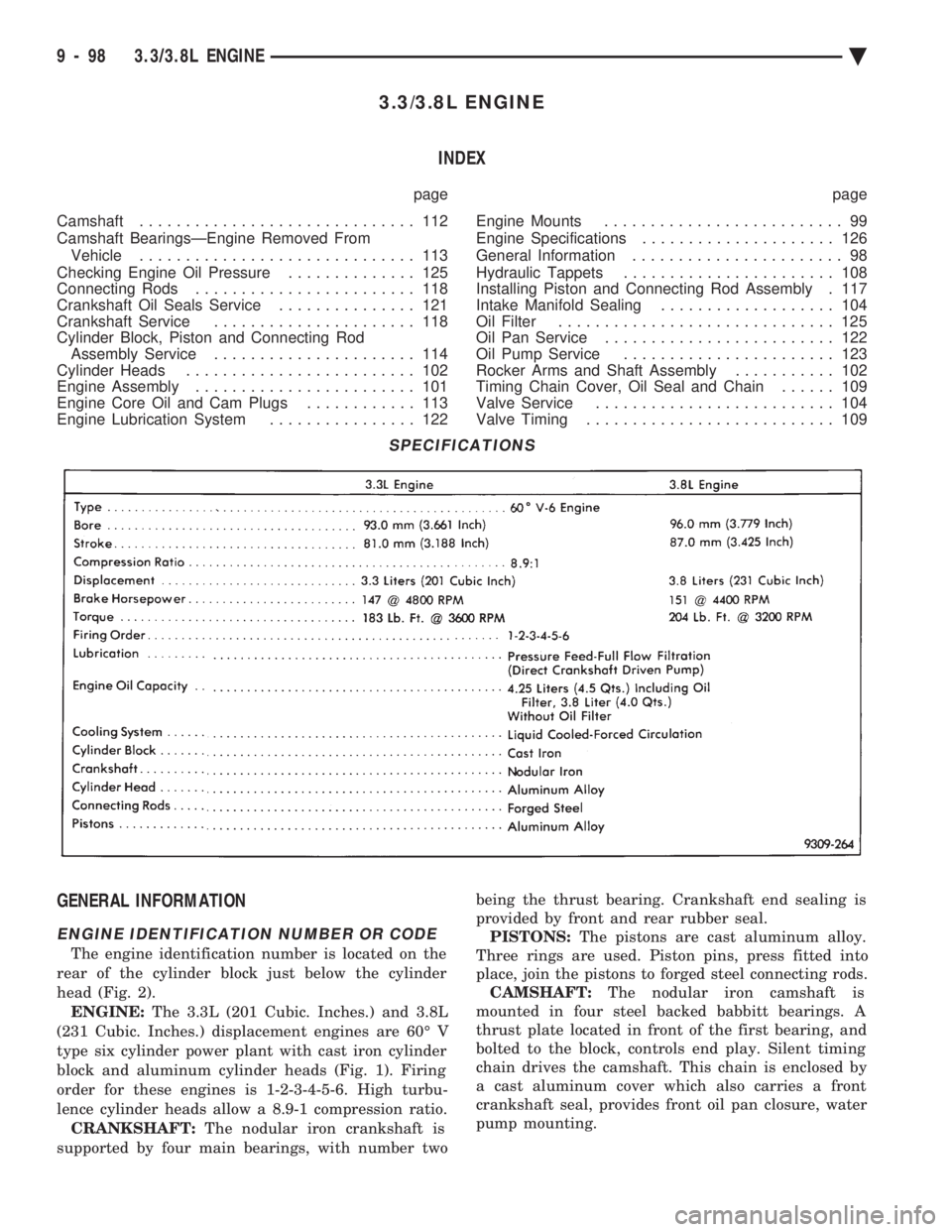
GENERAL INFORMATION
ENGINE IDENTIFICATION NUMBER OR CODE
The engine identification number is located on the
rear of the cylinder block just below the cylinder
head (Fig. 2). ENGINE: The 3.3L (201 Cubic. Inches.) and 3.8L
(231 Cubic. Inches.) displacement engines are 60É V
type six cylinder power plant with cast iron cylinder
block and aluminum cylinder heads (Fig. 1). Firing
order for these engines is 1-2-3-4-5-6. High turbu-
lence cylinder heads allow a 8.9-1 compression ratio. CRANKSHAFT: The nodular iron crankshaft is
supported by four main bearings, with number two being the thrust bearing. Crankshaft end sealing is
provided by front and rear rubber seal. PISTONS: The pistons are cast aluminum alloy.
Three rings are used. Piston pins, press fitted into
place, join the pistons to forged steel connecting rods. CAMSHAFT: The nodular iron camshaft is
mounted in four steel backed babbitt bearings. A
thrust plate located in front of the first bearing, and
bolted to the block, controls end play. Silent timing
chain drives the camshaft. This chain is enclosed by
a cast aluminum cover which also carries a front
crankshaft seal, provides front oil pan closure, water
pump mounting.
SPECIFICATIONS
9 - 98 3.3/3.8L ENGINE Ä
Page 1667 of 2438
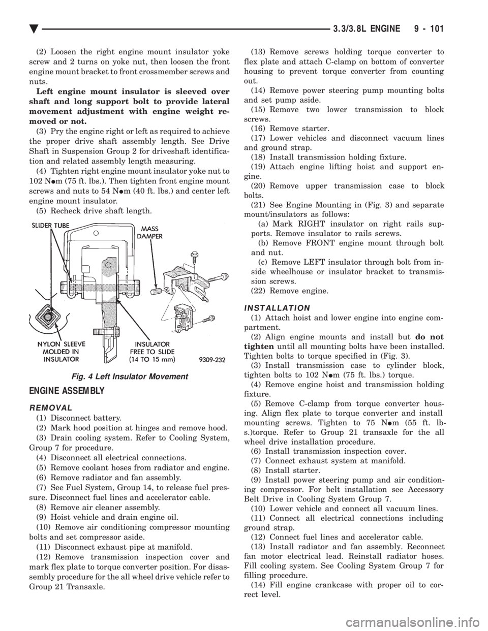
(2) Loosen the right engine mount insulator yoke
screw and 2 turns on yoke nut, then loosen the front
engine mount bracket to front crossmember screws and
nuts. Left engine mount insulator is sleeved over
shaft and long support bolt to provide lateral
movement adjustment with engine weight re-
moved or not. (3) Pry the engine right or left as required to achieve
the proper drive shaft assembly length. See Drive
Shaft in Suspension Group 2 for driveshaft identifica-
tion and related assembly length measuring. (4) Tighten right engine mount insulator yoke nut to
102 N Im (75 ft. lbs.). Then tighten front engine mount
screws and nuts to 54 N Im (40 ft. lbs.) and center left
engine mount insulator. (5) Recheck drive shaft length.
ENGINE ASSEMBLY
REMOVAL
(1) Disconnect battery.
(2) Mark hood position at hinges and remove hood.
(3) Drain cooling system. Refer to Cooling System,
Group 7 for procedure. (4) Disconnect all electrical connections.
(5) Remove coolant hoses from radiator and engine.
(6) Remove radiator and fan assembly.
(7) See Fuel System, Group 14, to release fuel pres-
sure. Disconnect fuel lines and accelerator cable. (8) Remove air cleaner assembly.
(9) Hoist vehicle and drain engine oil.
(10) Remove air conditioning compressor mounting
bolts and set compressor aside. (11) Disconnect exhaust pipe at manifold.
(12) Remove transmission inspection cover and
mark flex plate to torque converter position. For disas-
sembly procedure for the all wheel drive vehicle refer to
Group 21 Transaxle. (13) Remove screws holding torque converter to
flex plate and attach C-clamp on bottom of converter
housing to prevent torque converter from counting
out. (14) Remove power steering pump mounting bolts
and set pump aside. (15) Remove two lower transmission to block
screws. (16) Remove starter.
(17) Lower vehicles and disconnect vacuum lines
and ground strap. (18) Install transmission holding fixture.
(19) Attach engine lifting hoist and support en-
gine. (20) Remove upper transmission case to block
bolts. (21) See Engine Mounting in (Fig. 3) and separate
mount/insulators as follows: (a) Mark RIGHT insulator on right rails sup-
ports. Remove insulator to rails screws. (b) Remove FRONT engine mount through bolt
and nut. (c) Remove LEFT insulator through bolt from in-
side wheelhouse or insulator bracket to transmis-
sion screws.
(22) Remove engine.
INSTALLATION
(1) Attach hoist and lower engine into engine com-
partment. (2) Align engine mounts and install but do not
tighten until all mounting bolts have been installed.
Tighten bolts to torque specified in (Fig. 3). (3) Install transmission case to cylinder block,
tighten bolts to 102 N Im (75 ft. lbs.) torque.
(4) Remove engine hoist and transmission holding
fixture. (5) Remove C-clamp from torque converter hous-
ing. Align flex plate to torque converter and install
mounting screws. Tighten to 75 N Im (55 ft. lb-
s.)torque. Refer to Group 21 transaxle for the all
wheel drive installation procedure. (6) Install transmission inspection cover.
(7) Connect exhaust system at manifold.
(8) Install starter.
(9) Install power steering pump and air condition-
ing compressor. For belt installation see Accessory
Belt Drive in Cooling System Group 7. (10) Lower vehicle and connect all vacuum lines.
(11) Connect all electrical connections including
ground strap. (12) Connect fuel lines and accelerator cable.
(13) Install radiator and fan assembly. Reconnect
fan motor electrical lead. Reinstall radiator hoses.
Fill cooling system. See Cooling System Group 7 for
filling procedure. (14) Fill engine crankcase with proper oil to cor-
rect level.
Fig. 4 Left Insulator Movement
Ä 3.3/3.8L ENGINE 9 - 101