1993 CHEVROLET DYNASTY oil
[x] Cancel search: oilPage 1708 of 2438
CAUTION: When using the ASD Fuel System Test,
the Auto Shutdown (ASD) relay will remain ener-
gized for 7 minutes or until the ignition switch is
turned to the OFF position, or Stop All Test is se-
lected.
TURBOCHARGER
REMOVAL
The turbocharger is removed from below the vehi-
cle. Cylinder head removal for component accessibil-
ity is not required. (1) Disconnect negative battery cable. Remove Air
Cleaner assembly (Fig. 1). (2) From Above: Remove front engine mount
through bolt and rotate engine (Top) forward away
from cowl. Refer to Engine Removal in Engine,
Group 9. (3) Remove Air Cleaner Support (Fig. 1).
(4) Disconnect Heated Oxygen sensor lead wire
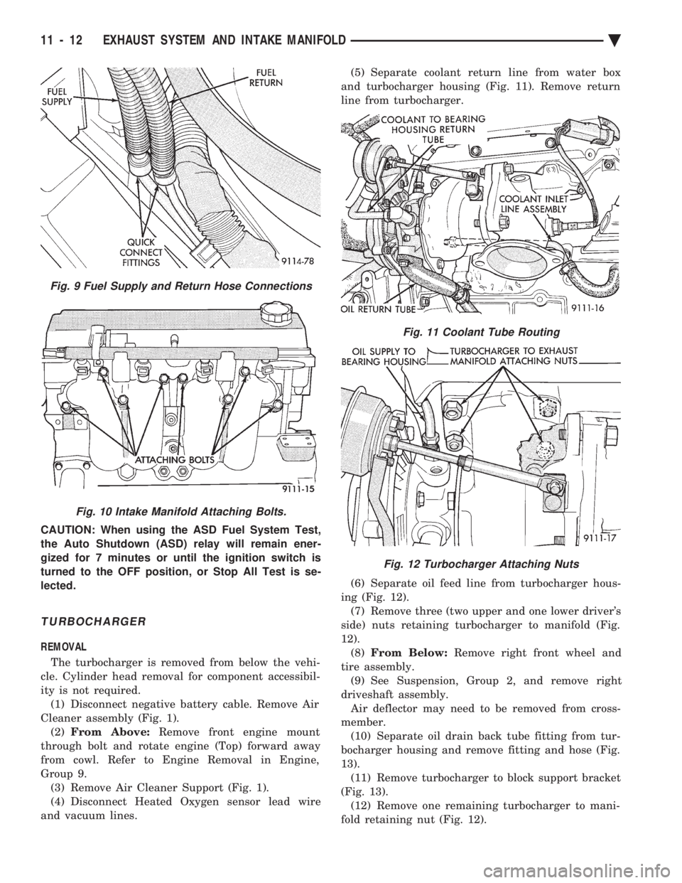
and vacuum lines. (5) Separate coolant return line from water box
and turbocharger housing (Fig. 11). Remove return
line from turbocharger.
(6) Separate oil feed line from turbocharger hous-
ing (Fig. 12). (7) Remove three (two upper and one lower driver's
side) nuts retaining turbocharger to manifold (Fig.
12). (8) From Below: Remove right front wheel and
tire assembly. (9) See Suspension, Group 2, and remove right
driveshaft assembly. Air deflector may need to be removed from cross-
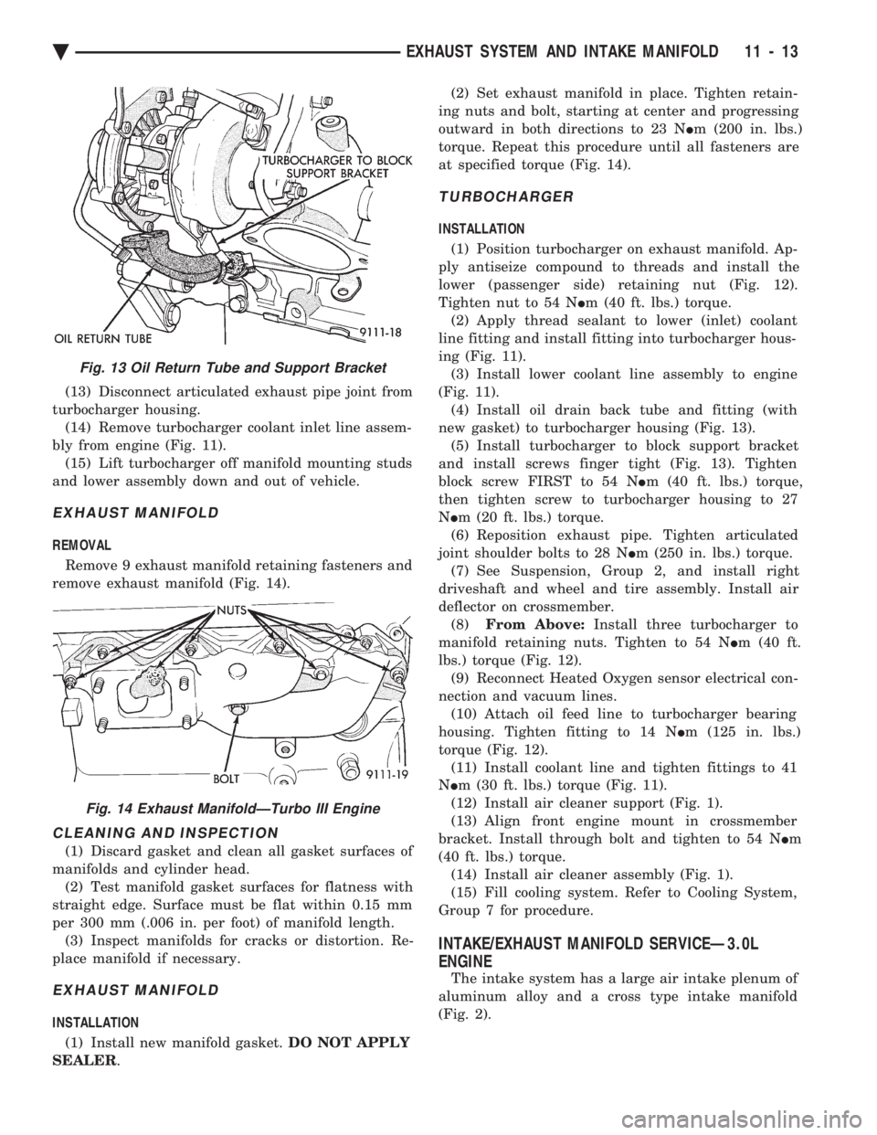
member. (10) Separate oil drain back tube fitting from tur-
bocharger housing and remove fitting and hose (Fig.
13). (11) Remove turbocharger to block support bracket
(Fig. 13). (12) Remove one remaining turbocharger to mani-
fold retaining nut (Fig. 12).
Fig. 11 Coolant Tube Routing
Fig. 12 Turbocharger Attaching Nuts
Fig. 9 Fuel Supply and Return Hose Connections
Fig. 10 Intake Manifold Attaching Bolts.
11 - 12 EXHAUST SYSTEM AND INTAKE MANIFOLD Ä
Page 1709 of 2438
(13) Disconnect articulated exhaust pipe joint from
turbocharger housing. (14) Remove turbocharger coolant inlet line assem-
bly from engine (Fig. 11). (15) Lift turbocharger off manifold mounting studs
and lower assembly down and out of vehicle.
EXHAUST MANIFOLD
REMOVAL
Remove 9 exhaust manifold retaining fasteners and
remove exhaust manifold (Fig. 14).
CLEANING AND INSPECTION
(1) Discard gasket and clean all gasket surfaces of
manifolds and cylinder head. (2) Test manifold gasket surfaces for flatness with
straight edge. Surface must be flat within 0.15 mm
per 300 mm (.006 in. per foot) of manifold length. (3) Inspect manifolds for cracks or distortion. Re-
place manifold if necessary.
EXHAUST MANIFOLD
INSTALLATION
(1) Install new manifold gasket. DO NOT APPLY
SEALER . (2) Set exhaust manifold in place. Tighten retain-
ing nuts and bolt, starting at center and progressing
outward in both directions to 23 N Im (200 in. lbs.)
torque. Repeat this procedure until all fasteners are
at specified torque (Fig. 14).
TURBOCHARGER
INSTALLATION
(1) Position turbocharger on exhaust manifold. Ap-
ply antiseize compound to threads and install the
lower (passenger side) retaining nut (Fig. 12).
Tighten nut to 54 N Im (40 ft. lbs.) torque.
(2) Apply thread sealant to lower (inlet) coolant
line fitting and install fitting into turbocharger hous-
ing (Fig. 11). (3) Install lower coolant line assembly to engine
(Fig. 11). (4) Install oil drain back tube and fitting (with
new gasket) to turbocharger housing (Fig. 13). (5) Install turbocharger to block support bracket
and install screws finger tight (Fig. 13). Tighten
block screw FIRST to 54 N Im (40 ft. lbs.) torque,
then tighten screw to turbocharger housing to 27
N Im (20 ft. lbs.) torque.
(6) Reposition exhaust pipe. Tighten articulated
joint shoulder bolts to 28 N Im (250 in. lbs.) torque.
(7) See Suspension, Group 2, and install right
driveshaft and wheel and tire assembly. Install air
deflector on crossmember. (8) From Above: Install three turbocharger to
manifold retaining nuts. Tighten to 54 N Im (40 ft.
lbs.) torque (Fig. 12). (9) Reconnect Heated Oxygen sensor electrical con-
nection and vacuum lines. (10) Attach oil feed line to turbocharger bearing
housing. Tighten fitting to 14 N Im (125 in. lbs.)
torque (Fig. 12). (11) Install coolant line and tighten fittings to 41
N Im (30 ft. lbs.) torque (Fig. 11).
(12) Install air cleaner support (Fig. 1).
(13) Align front engine mount in crossmember
bracket. Install through bolt and tighten to 54 N Im
(40 ft. lbs.) torque. (14) Install air cleaner assembly (Fig. 1).
(15) Fill cooling system. Refer to Cooling System,
Group 7 for procedure.
INTAKE/EXHAUST MANIFOLD SERVICEÐ3.0L
ENGINE
The intake system has a large air intake plenum of
aluminum alloy and a cross type intake manifold
(Fig. 2).
Fig. 13 Oil Return Tube and Support Bracket
Fig. 14 Exhaust ManifoldÐTurbo III Engine
Ä EXHAUST SYSTEM AND INTAKE MANIFOLD 11 - 13
Page 1711 of 2438
(e) Remove jumper wires.
(f) Continue fuel system service.
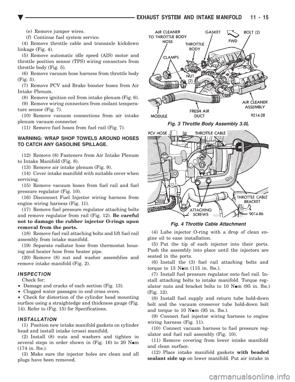
(4) Remove throttle cable and transaxle kickdown
linkage (Fig. 4). (5) Remove automatic idle speed (AIS) motor and
throttle position sensor (TPS) wiring connectors from
throttle body (Fig. 5). (6) Remove vacuum hose harness from throttle body
(Fig. 5). (7) Remove PCV and Brake booster hoses from Air
Intake Plenum. (8) Remove ignition coil from intake plenum (Fig. 6).
(9) Remove wiring connectors from coolant tempera-
ture sensor (Fig. 7). (10) Remove vacuum connections from air intake
plenum vacuum connector. (11) Remove fuel hoses from fuel rail (Fig. 7).
WARNING: WRAP SHOP TOWELS AROUND HOSES
TO CATCH ANY GASOLINE SPILLAGE. (12) Remove (8) Fasteners from Air Intake Plenum
to Intake Manifold (Fig. 8). (13) Remove air intake plenum (Fig. 9).
(14) Cover intake manifold with suitable cover when
servicing. (15) Remove vacuum hoses from fuel rail and fuel
pressure regulator (Fig. 10). (16) Disconnect Fuel Injector wiring harness from
engine wiring harness (Fig. 11). (17) Remove fuel pressure regulator attaching bolts
and remove regulator from rail (Fig. 12). Be careful
not to damage the rubber injector O-rings upon
removal from the ports. (18) Remove fuel rail attaching bolts and lift fuel rail
assembly from intake manifold. (19) Separate radiator hose from thermostat hous-
ing and heater hose from heater pipe. (20) Remove (8) nut and washer assemblies and
remove intake manifold (Fig. 2).
INSPECTION
Check for:
² Damage and cracks of each section (Fig. 13).
² Clogged water passages in end cross overs.
² Check for distortion of the cylinder head mounting
surface using a straightedge and thickness gauge (Fig.
14). Refer to (Fig. 15) for Specifications.
INSTALLATION
(1) Position new intake manifold gaskets on cylinder
head and install intake (cross) manifold. (2) Install (8) nuts and washers and tighten in
several steps in order shown in (Fig. 16) to 20 N Im
(174 in. lbs.). (3) Make sure the injector holes are clean and all
plugs have been removed. (4) Lube injector O-ring with a drop of clean en-
gine oil to ease installation. (5) Put the tip of each injector into their ports.
Push the assembly into place until the injectors are
seated in the ports. (6) Install the (3) fuel rail attaching bolts and
torque to 13 N Im (115 in. lbs.).
(7) Install fuel pressure regulator onto fuel rail. In-
stall attaching bolts to intake manifold. Torque reg-
ulator nuts and bracket bolts to 10 N Im (95 in. lbs.)
(Fig. 12). (8) Install fuel supply and return tube hold-down
bolt and the vacuum crossover tube hold-down bolt
and torque to 10 N Im (95 in. lbs.).
(9) Connect fuel injector wiring harness to engine
wiring harness (Fig. 11). (10) Connect vacuum harness to fuel pressure reg-
ulator and fuel rail assembly (Fig. 10). (11) Remove covering from lower intake manifold
and clean surface. (12) Place intake manifold gaskets with beaded
sealant side up on lower manifold. Put air intake in
Fig. 3 Throttle Body Assembly 3.0L
Fig. 4 Throttle Cable Attachment
Ä EXHAUST SYSTEM AND INTAKE MANIFOLD 11 - 15
Page 1712 of 2438
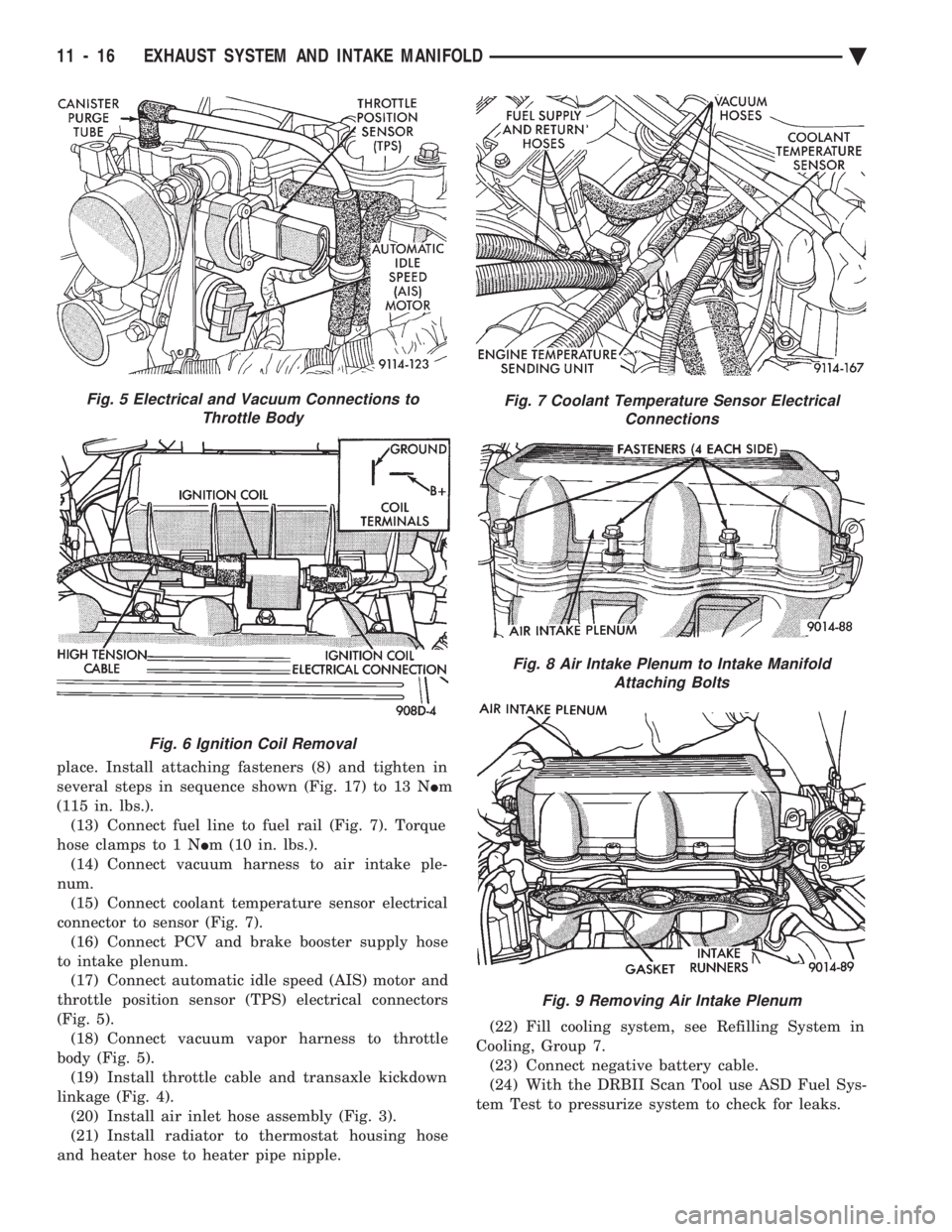
place. Install attaching fasteners (8) and tighten in
several steps in sequence shown (Fig. 17) to 13 N Im
(115 in. lbs.). (13) Connect fuel line to fuel rail (Fig. 7). Torque
hose clamps to 1 N Im (10 in. lbs.).
(14) Connect vacuum harness to air intake ple-
num. (15) Connect coolant temperature sensor electrical
connector to sensor (Fig. 7). (16) Connect PCV and brake booster supply hose
to intake plenum. (17) Connect automatic idle speed (AIS) motor and
throttle position sensor (TPS) electrical connectors
(Fig. 5). (18) Connect vacuum vapor harness to throttle
body (Fig. 5). (19) Install throttle cable and transaxle kickdown
linkage (Fig. 4). (20) Install air inlet hose assembly (Fig. 3).
(21) Install radiator to thermostat housing hose
and heater hose to heater pipe nipple. (22) Fill cooling system, see Refilling System in
Cooling, Group 7. (23) Connect negative battery cable.
(24) With the DRBII Scan Tool use ASD Fuel Sys-
tem Test to pressurize system to check for leaks.
Fig. 5 Electrical and Vacuum Connections to Throttle Body
Fig. 6 Ignition Coil Removal
Fig. 7 Coolant Temperature Sensor Electrical Connections
Fig. 8 Air Intake Plenum to Intake ManifoldAttaching Bolts
Fig. 9 Removing Air Intake Plenum
11 - 16 EXHAUST SYSTEM AND INTAKE MANIFOLD Ä
Page 1717 of 2438
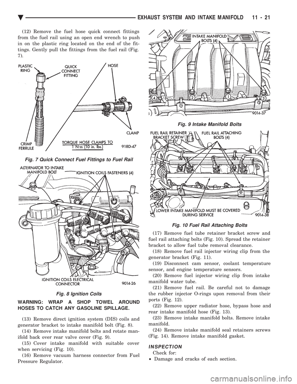
(12) Remove the fuel hose quick connect fittings
from the fuel rail using an open end wrench to push
in on the plastic ring located on the end of the fit-
tings. Gently pull the fittings from the fuel rail (Fig.
7).
WARNING: WRAP A SHOP TOWEL AROUND
HOSES TO CATCH ANY GASOLINE SPILLAGE.
(13) Remove direct ignition system (DIS) coils and
generator bracket to intake manifold bolt (Fig. 8). (14) Remove intake manifold bolts and rotate man-
ifold back over rear valve cover (Fig. 9). (15) Cover intake manifold with suitable cover
when servicing (Fig. 10). (16) Remove vacuum harness connector from Fuel
Pressure Regulator. (17) Remove fuel tube retainer bracket screw and
fuel rail attaching bolts (Fig. 10). Spread the retainer
bracket to allow fuel tube removal clearance. (18) Remove fuel rail injector wiring clip from the
generator bracket (Fig. 11). (19) Disconnect cam sensor, coolant temperature
sensor, and engine temperature sensors. (20) Remove fuel injector wiring clip from intake
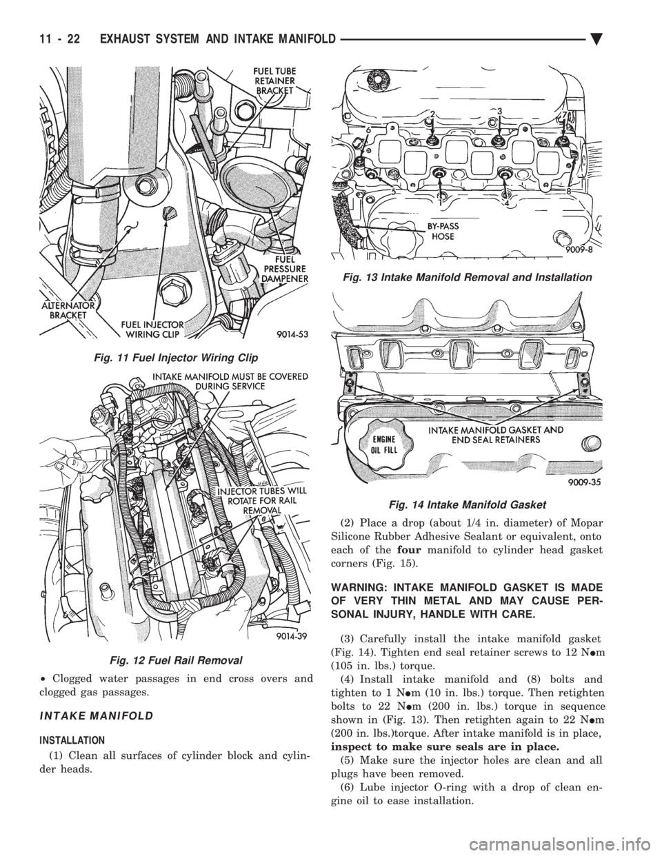
manifold water tube. (21) Remove fuel rail. Be careful not to damage
the rubber injector O-rings upon removal from their
ports (Fig. 12). (22) Remove upper radiator hose, bypass hose and
rear intake manifold hose (Fig. 13). (23) Remove intake manifold bolts. Remove intake
manifold. (24) Remove intake manifold seal retainers screws
(Fig. 14). Remove intake manifold gasket.
INSPECTION
Check for:
² Damage and cracks of each section.
Fig. 7 Quick Connect Fuel Fittings to Fuel Rail
Fig. 8 Ignition Coils
Fig. 9 Intake Manifold Bolts
Fig. 10 Fuel Rail Attaching Bolts
Ä EXHAUST SYSTEM AND INTAKE MANIFOLD 11 - 21
Page 1718 of 2438
² Clogged water passages in end cross overs and
clogged gas passages.
INTAKE MANIFOLD
INSTALLATION
(1) Clean all surfaces of cylinder block and cylin-
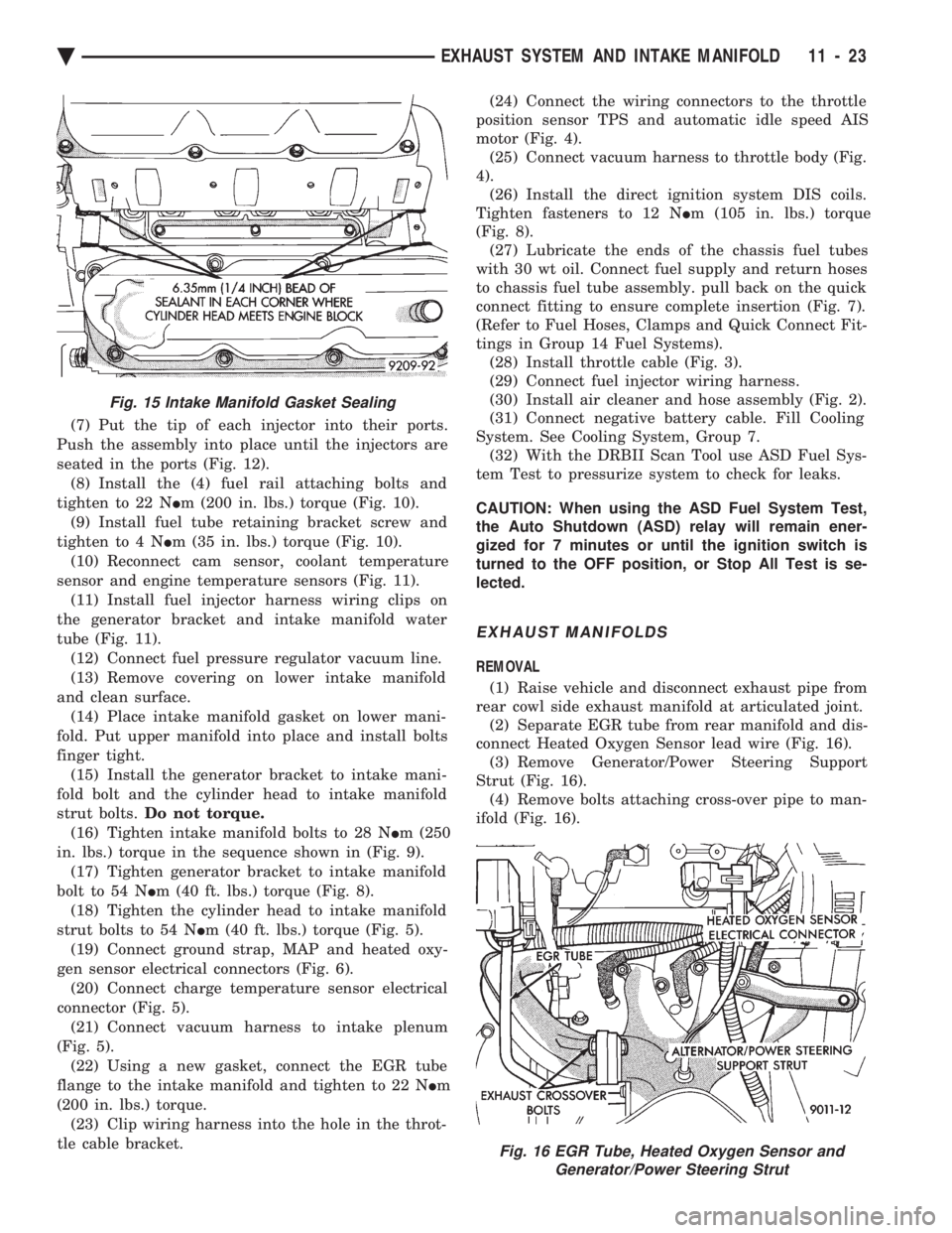
der heads. (2) Place a drop (about 1/4 in. diameter) of Mopar
Silicone Rubber Adhesive Sealant or equivalent, onto
each of the fourmanifold to cylinder head gasket
corners (Fig. 15).
WARNING: INTAKE MANIFOLD GASKET IS MADE
OF VERY THIN METAL AND MAY CAUSE PER-
SONAL INJURY, HANDLE WITH CARE.
(3) Carefully install the intake manifold gasket
(Fig. 14). Tighten end seal retainer screws to 12 N Im
(105 in. lbs.) torque. (4) Install intake manifold and (8) bolts and
tighten to 1 N Im (10 in. lbs.) torque. Then retighten
bolts to 22 N Im (200 in. lbs.) torque in sequence
shown in (Fig. 13). Then retighten again to 22 N Im
(200 in. lbs.)torque. After intake manifold is in place,
inspect to make sure seals are in place. (5) Make sure the injector holes are clean and all
plugs have been removed. (6) Lube injector O-ring with a drop of clean en-
gine oil to ease installation.
Fig. 11 Fuel Injector Wiring Clip
Fig. 12 Fuel Rail Removal
Fig. 13 Intake Manifold Removal and Installation
Fig. 14 Intake Manifold Gasket
11 - 22 EXHAUST SYSTEM AND INTAKE MANIFOLD Ä
Page 1719 of 2438
(7) Put the tip of each injector into their ports.
Push the assembly into place until the injectors are
seated in the ports (Fig. 12). (8) Install the (4) fuel rail attaching bolts and
tighten to 22 N Im (200 in. lbs.) torque (Fig. 10).
(9) Install fuel tube retaining bracket screw and
tighten to 4 N Im (35 in. lbs.) torque (Fig. 10).
(10) Reconnect cam sensor, coolant temperature
sensor and engine temperature sensors (Fig. 11). (11) Install fuel injector harness wiring clips on
the generator bracket and intake manifold water
tube (Fig. 11). (12) Connect fuel pressure regulator vacuum line.
(13) Remove covering on lower intake manifold
and clean surface. (14) Place intake manifold gasket on lower mani-
fold. Put upper manifold into place and install bolts
finger tight. (15) Install the generator bracket to intake mani-
fold bolt and the cylinder head to intake manifold
strut bolts. Do not torque.
(16) Tighten intake manifold bolts to 28 N Im (250
in. lbs.) torque in the sequence shown in (Fig. 9). (17) Tighten generator bracket to intake manifold
bolt to 54 N Im (40 ft. lbs.) torque (Fig. 8).
(18) Tighten the cylinder head to intake manifold
strut bolts to 54 N Im (40 ft. lbs.) torque (Fig. 5).
(19) Connect ground strap, MAP and heated oxy-
gen sensor electrical connectors (Fig. 6). (20) Connect charge temperature sensor electrical
connector (Fig. 5). (21) Connect vacuum harness to intake plenum
(Fig. 5). (22) Using a new gasket, connect the EGR tube
flange to the intake manifold and tighten to 22 N Im
(200 in. lbs.) torque. (23) Clip wiring harness into the hole in the throt-
tle cable bracket. (24) Connect the wiring connectors to the throttle
position sensor TPS and automatic idle speed AIS
motor (Fig. 4). (25) Connect vacuum harness to throttle body (Fig.
4). (26) Install the direct ignition system DIS coils.
Tighten fasteners to 12 N Im (105 in. lbs.) torque
(Fig. 8). (27) Lubricate the ends of the chassis fuel tubes
with 30 wt oil. Connect fuel supply and return hoses
to chassis fuel tube assembly. pull back on the quick
connect fitting to ensure complete insertion (Fig. 7).
(Refer to Fuel Hoses, Clamps and Quick Connect Fit-
tings in Group 14 Fuel Systems). (28) Install throttle cable (Fig. 3).
(29) Connect fuel injector wiring harness.
(30) Install air cleaner and hose assembly (Fig. 2).
(31) Connect negative battery cable. Fill Cooling
System. See Cooling System, Group 7. (32) With the DRBII Scan Tool use ASD Fuel Sys-
tem Test to pressurize system to check for leaks.
CAUTION: When using the ASD Fuel System Test,
the Auto Shutdown (ASD) relay will remain ener-
gized for 7 minutes or until the ignition switch is
turned to the OFF position, or Stop All Test is se-
lected.
EXHAUST MANIFOLDS
REMOVAL
(1) Raise vehicle and disconnect exhaust pipe from
rear cowl side exhaust manifold at articulated joint. (2) Separate EGR tube from rear manifold and dis-
connect Heated Oxygen Sensor lead wire (Fig. 16). (3) Remove Generator/Power Steering Support
Strut (Fig. 16). (4) Remove bolts attaching cross-over pipe to man-
ifold (Fig. 16).
Fig. 15 Intake Manifold Gasket Sealing
Fig. 16 EGR Tube, Heated Oxygen Sensor and Generator/Power Steering Strut
Ä EXHAUST SYSTEM AND INTAKE MANIFOLD 11 - 23
Page 1758 of 2438
INSTALLATION
WARNING: FUEL TANKS DESIGNED FOR GASO-
LINE ONLY VEHICLES CANNOT BE USED ON
FLEXIBLE FUEL AA-BODY VEHICLES. WHEN SER-
VICING THE FUEL SYSTEM OF A FLEXIBLE FUEL
VEHICLE, ONLY USE ORIGINAL EQUIPMENT OR
EQUIVALENT REPLACEMENT COMPONENTS. (1) Position fuel tank on transmission jack. Con-
nect vapor separator/rollover valve hose and position
insulator pad on fuel tank. Position vapor vent so
that it is not pinched between tank and floor pan
during installation. (2) Raise tank and fuel filler tube carefully into
position. Use a light coating of power steering fluid
to ease fuel filler tube installation. Ensure filler tube
grommet is not damaged. Verify that the tube is in-
stalled correctly. (3) Tighten fuel tank strap nuts to 23 N Im (250 in.
lbs.) torque. Remove transmission jack. Ensure
straps are not twisted or bent. (4) Lubricate the metal tubes on the fuel pump
with clean 30 weight engine oil. Install the quick
connect fuel fittings. Refer to Quick Connect Fittings
in the Fuel Delivery section of this Group. (5) Attach electrical connector to fuel pump mod-
ule and level sensor unit. (6) Lower the vehicle.
(7) Attach filler tube to filler neck opening in
quarter panel. Tighten quarter panel screws to 2
N Im (17 in. lbs.) torque.
(8) Fill fuel tank, install filler cap, and connect
battery cable.
CAUTION: When using the ASD Fuel System Test,
the Auto Shutdown (ASD) Relay remains energized
for either 7 minutes, until the test is stopped, or un-
til the ignition switch is turned to the Off position.
(9) Use the DRBII scan tool ASD Fuel System Test
to pressurize the fuel system. Check for leaks.
FUEL PUMP MODULE
Refer to the Fuel Delivery section of this group.
METHANOL CONCENTRATION SENSOR
Refer to the Fuel Delivery section of this group.
FUEL RESERVOIR
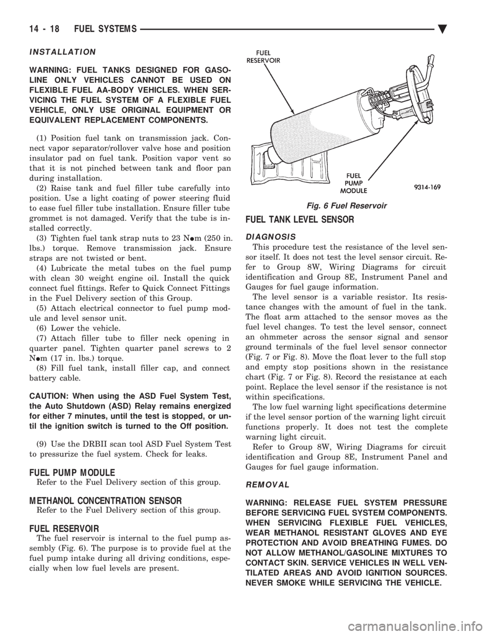
The fuel reservoir is internal to the fuel pump as-
sembly (Fig. 6). The purpose is to provide fuel at the
fuel pump intake during all driving conditions, espe-
cially when low fuel levels are present.
FUEL TANK LEVEL SENSOR
DIAGNOSIS
This procedure test the resistance of the level sen-
sor itself. It does not test the level sensor circuit. Re-
fer to Group 8W, Wiring Diagrams for circuit
identification and Group 8E, Instrument Panel and
Gauges for fuel gauge information. The level sensor is a variable resistor. Its resis-
tance changes with the amount of fuel in the tank.
The float arm attached to the sensor moves as the
fuel level changes. To test the level sensor, connect
an ohmmeter across the sensor signal and sensor
ground terminals of the fuel level sensor connector
(Fig. 7 or Fig. 8). Move the float lever to the full stop
and empty stop positions shown in the resistance
chart (Fig. 7 or Fig. 8). Record the resistance at each
point. Replace the level sensor if the resistance is not
within specifications. The low fuel warning light specifications determine
if the level sensor portion of the warning light circuit
functions properly. It does not test the complete
warning light circuit. Refer to Group 8W, Wiring Diagrams for circuit
identification and Group 8E, Instrument Panel and
Gauges for fuel gauge information.
REMOVAL
WARNING: RELEASE FUEL SYSTEM PRESSURE
BEFORE SERVICING FUEL SYSTEM COMPONENTS.
WHEN SERVICING FLEXIBLE FUEL VEHICLES,
WEAR METHANOL RESISTANT GLOVES AND EYE
PROTECTION AND AVOID BREATHING FUMES. DO
NOT ALLOW METHANOL/GASOLINE MIXTURES TO
CONTACT SKIN. SERVICE VEHICLES IN WELL VEN-
TILATED AREAS AND AVOID IGNITION SOURCES.
NEVER SMOKE WHILE SERVICING THE VEHICLE.
Fig. 6 Fuel Reservoir
14 - 18 FUEL SYSTEMS Ä