1993 CHEVROLET DYNASTY oil
[x] Cancel search: oilPage 1679 of 2438
(9) Measure camshaft end play. End Play should
measure .0127 to .304 mm (.005 to .012 inches.) .310
mm (.012 inch. Max.). If not within limits install a new
thrust plate. (10) Each tappet reused must be installed in the
same position from which it was removed. When
camshaft is replaced, all of the tappets must be
replaced .
CAMSHAFT BEARINGSÐENGINE REMOVED FROM
VEHICLE
REMOVAL
(1) With engine completely disassembled, drive out
rear cam bearing core hole plug. (2) Install proper size adapters and horseshoe wash-
ers (part of Tool C-3132-A) at back of each bearing shell
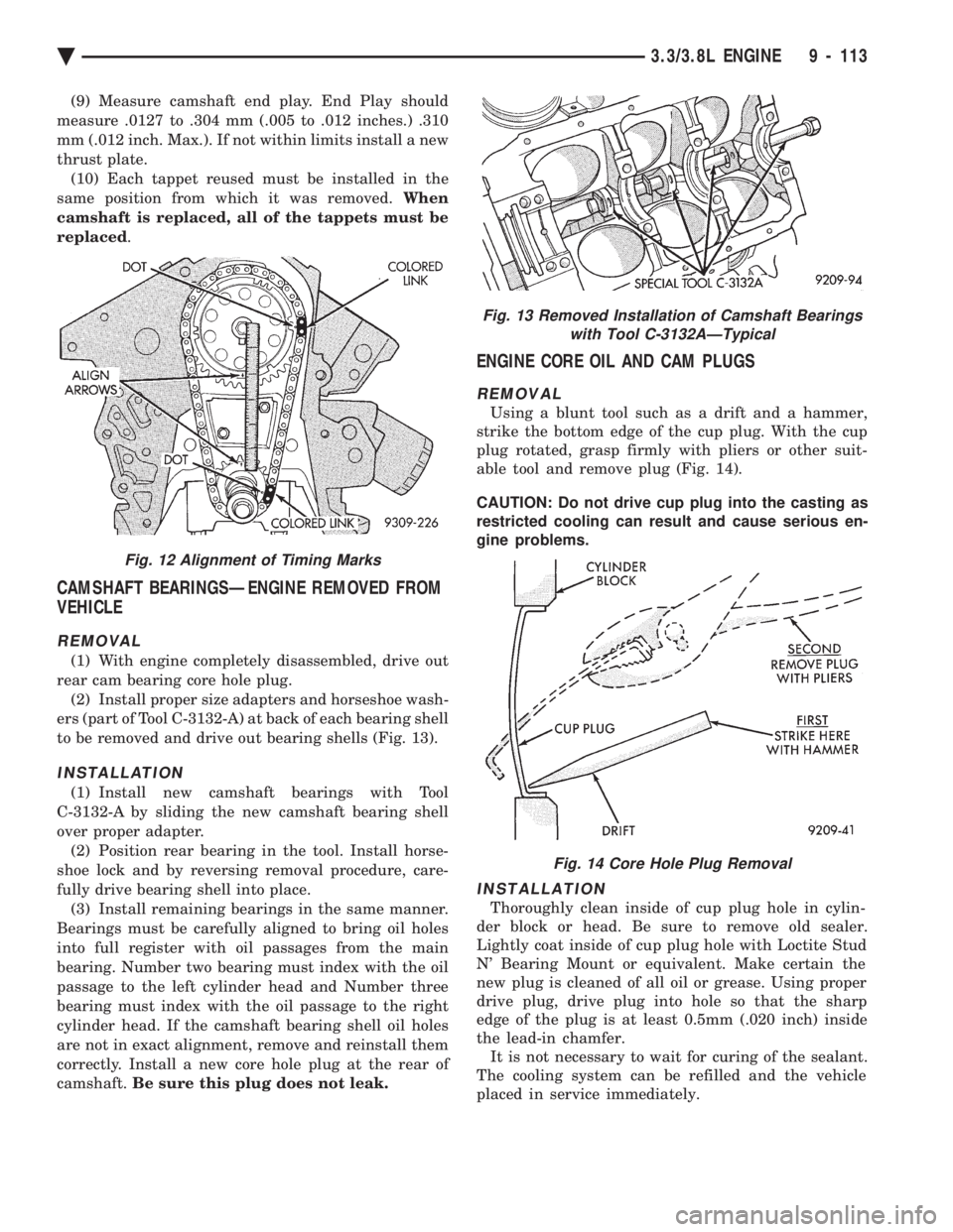
to be removed and drive out bearing shells (Fig. 13).
INSTALLATION
(1) Install new camshaft bearings with Tool
C-3132-A by sliding the new camshaft bearing shell
over proper adapter. (2) Position rear bearing in the tool. Install horse-
shoe lock and by reversing removal procedure, care-
fully drive bearing shell into place. (3) Install remaining bearings in the same manner.
Bearings must be carefully aligned to bring oil holes
into full register with oil passages from the main
bearing. Number two bearing must index with the oil
passage to the left cylinder head and Number three
bearing must index with the oil passage to the right
cylinder head. If the camshaft bearing shell oil holes
are not in exact alignment, remove and reinstall them
correctly. Install a new core hole plug at the rear of
camshaft. Be sure this plug does not leak.
ENGINE CORE OIL AND CAM PLUGS
REMOVAL
Using a blunt tool such as a drift and a hammer,
strike the bottom edge of the cup plug. With the cup
plug rotated, grasp firmly with pliers or other suit-
able tool and remove plug (Fig. 14).
CAUTION: Do not drive cup plug into the casting as
restricted cooling can result and cause serious en-
gine problems.
INSTALLATION
Thoroughly clean inside of cup plug hole in cylin-
der block or head. Be sure to remove old sealer.
Lightly coat inside of cup plug hole with Loctite Stud
N' Bearing Mount or equivalent. Make certain the
new plug is cleaned of all oil or grease. Using proper
drive plug, drive plug into hole so that the sharp
edge of the plug is at least 0.5mm (.020 inch) inside
the lead-in chamfer. It is not necessary to wait for curing of the sealant.
The cooling system can be refilled and the vehicle
placed in service immediately.
Fig. 13 Removed Installation of Camshaft Bearings with Tool C-3132AÐTypical
Fig. 14 Core Hole Plug Removal
Fig. 12 Alignment of Timing Marks
Ä 3.3/3.8L ENGINE 9 - 113
Page 1680 of 2438
CYLINDER BLOCK, PISTON AND CONNECTING ROD ASSEMBLY SERVICE
CYLINDER BLOCK PISTONÐREMOVAL
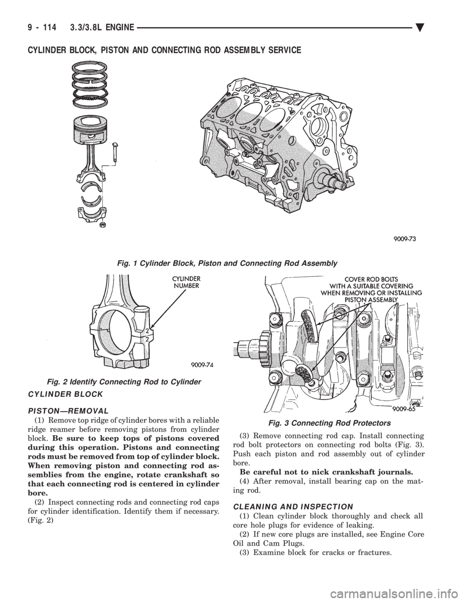
(1) Remove top ridge of cylinder bores with a reliable
ridge reamer before removing pistons from cylinder
block. Be sure to keep tops of pistons covered
during this operation. Pistons and connecting
rods must be removed from top of cylinder block.
When removing piston and connecting rod as-
semblies from the engine, rotate crankshaft so
that each connecting rod is centered in cylinder
bore. (2) Inspect connecting rods and connecting rod caps
for cylinder identification. Identify them if necessary.
(Fig. 2) (3) Remove connecting rod cap. Install connecting
rod bolt protectors on connecting rod bolts (Fig. 3).
Push each piston and rod assembly out of cylinder
bore. Be careful not to nick crankshaft journals.
(4) After removal, install bearing cap on the mat-
ing rod.
CLEANING AND INSPECTION
(1) Clean cylinder block thoroughly and check all
core hole plugs for evidence of leaking. (2) If new core plugs are installed, see Engine Core
Oil and Cam Plugs. (3) Examine block for cracks or fractures.
Fig. 1 Cylinder Block, Piston and Connecting Rod Assembly
Fig. 2 Identify Connecting Rod to Cylinder
Fig. 3 Connecting Rod Protectors
9 - 114 3.3/3.8L ENGINE Ä
Page 1682 of 2438
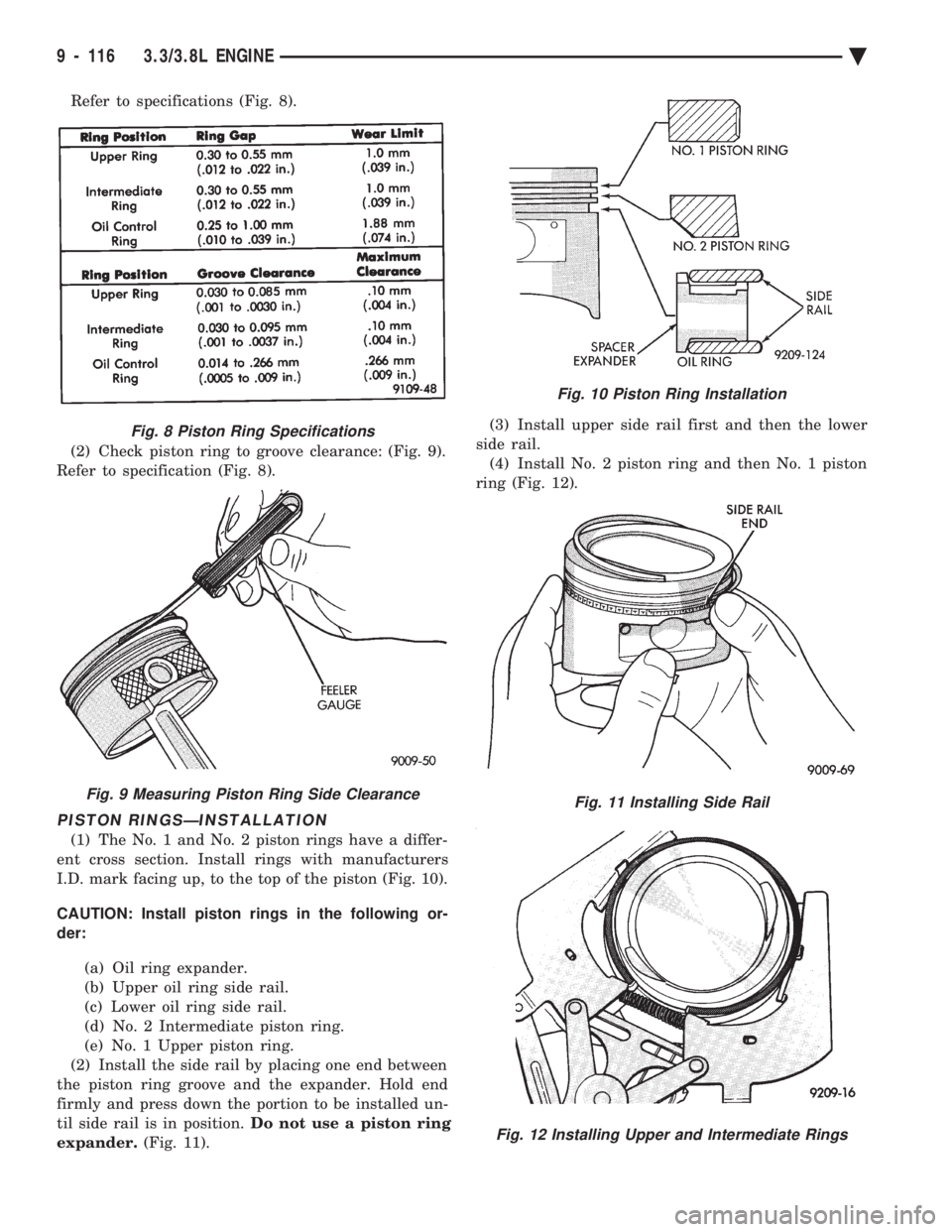
Refer to specifications (Fig. 8).
(2) Check piston ring to groove clearance: (Fig. 9).
Refer to specification (Fig. 8).
PISTON RINGSÐINSTALLATION
(1) The No. 1 and No. 2 piston rings have a differ-
ent cross section. Install rings with manufacturers
I.D. mark facing up, to the top of the piston (Fig. 10).
CAUTION: Install piston rings in the following or-
der:
(a) Oil ring expander.
(b) Upper oil ring side rail.
(c) Lower oil ring side rail.
(d) No. 2 Intermediate piston ring.
(e) No. 1 Upper piston ring.
(2) Install the side rail by placing one end between
the piston ring groove and the expander. Hold end
firmly and press down the portion to be installed un-
til side rail is in position. Do not use a piston ring
expander. (Fig. 11). (3) Install upper side rail first and then the lower
side rail. (4) Install No. 2 piston ring and then No. 1 piston
ring (Fig. 12).
Fig. 8 Piston Ring Specifications
Fig. 9 Measuring Piston Ring Side Clearance
Fig. 10 Piston Ring Installation
Fig. 11 Installing Side Rail
Fig. 12 Installing Upper and Intermediate Rings
9 - 116 3.3/3.8L ENGINE Ä
Page 1683 of 2438
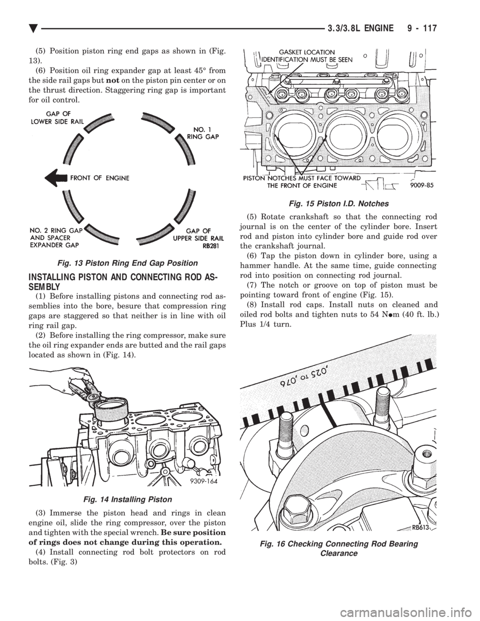
(5) Position piston ring end gaps as shown in (Fig.
13). (6) Position oil ring expander gap at least 45É from
the side rail gaps but noton the piston pin center or on
the thrust direction. Staggering ring gap is important
for oil control.
INSTALLING PISTON AND CONNECTING ROD AS-
SEMBLY
(1) Before installing pistons and connecting rod as-
semblies into the bore, besure that compression ring
gaps are staggered so that neither is in line with oil
ring rail gap. (2) Before installing the ring compressor, make sure
the oil ring expander ends are butted and the rail gaps
located as shown in (Fig. 14).
(3) Immerse the piston head and rings in clean
engine oil, slide the ring compressor, over the piston
and tighten with the special wrench. Be sure position
of rings does not change during this operation. (4) Install connecting rod bolt protectors on rod
bolts. (Fig. 3) (5) Rotate crankshaft so that the connecting rod
journal is on the center of the cylinder bore. Insert
rod and piston into cylinder bore and guide rod over
the crankshaft journal. (6) Tap the piston down in cylinder bore, using a
hammer handle. At the same time, guide connecting
rod into position on connecting rod journal. (7) The notch or groove on top of piston must be
pointing toward front of engine (Fig. 15). (8) Install rod caps. Install nuts on cleaned and
oiled rod bolts and tighten nuts to 54 N Im (40 ft. lb.)
Plus 1/4 turn.
Fig. 15 Piston I.D. Notches
Fig. 16 Checking Connecting Rod Bearing Clearance
Fig. 13 Piston Ring End Gap Position
Fig. 14 Installing Piston
Ä 3.3/3.8L ENGINE 9 - 117
Page 1684 of 2438
CONNECTING RODS
INSTALLATION OF CONNECTING ROD BEAR- INGS
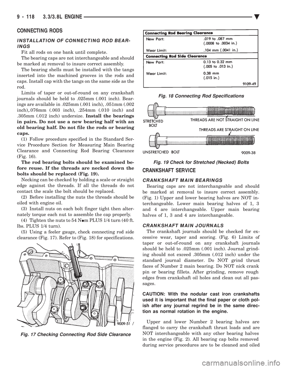
Fit all rods on one bank until complete.
The bearing caps are not interchangeable and should
be marked at removal to insure correct assembly. The bearing shells must be installed with the tangs
inserted into the machined grooves in the rods and
caps. Install cap with the tangs on the same side as the
rod. Limits of taper or out-of-round on any crankshaft
journals should be held to .025mm (.001 inch). Bear-
ings are available in .025mm (.001 inch), .051mm (.002
inch),.076mm (.003 inch), .254mm (.010 inch) and
.305mm (.012 inch) undersize. Install the bearings
in pairs. Do not use a new bearing half with an
old bearing half. Do not file the rods or bearing
caps. (1) Follow procedure specified in the Standard Ser-
vice Procedure Section for Measuring Main Bearing
Clearance and Connecting Rod Bearing Clearance
(Fig. 16). The rod bearing bolts should be examined be-
fore reuse. If the threads are necked down the
bolts should be replaced (Fig. 19). Necking can be checked by holding a scale or straight
edge against the threads. If all the threads do not
contact the scale the bolt should be replaced. (2) Before installing the nuts the threads should be
oiled with engine oil. (3) Install nuts on each bolt finger tight then alter-
nately torque each nut to assemble the cap properly. (4) Tighten the nuts to 54 N Im PLUS 1/4 turn (40 ft.
lbs. PLUS 1/4 turn). (5) Using a feeler gauge, check connecting rod side
clearance (Fig. 17). Refer to (Fig. 18) for specifications.
CRANKSHAFT SERVICE
CRANKSHAFT MAIN BEARINGS
Bearing caps are not interchangeable and should
be marked at removal to insure correct assembly.
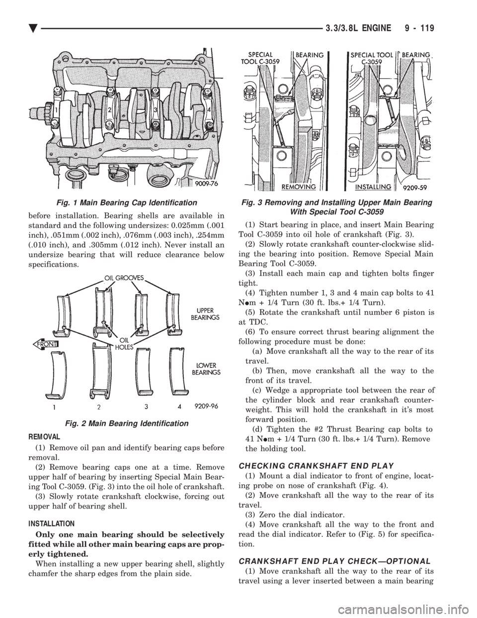
(Fig. 1) Upper and lower bearing halves are NOT in-
terchangeable. Lower main bearing halves of 1, 3
and 4 are interchangeable. Upper main bearing
halves of 1, 3 and 4 are interchangeable.
CRANKSHAFT MAIN JOURNALS
The crankshaft journals should be checked for ex-
cessive wear, taper and scoring. (Fig. 6) Limits of
taper or out-of-round on any crankshaft journals
should be held to .025mm (.001 inch). Journal grind-
ing should not exceed .305mm (.012 inch) under the
standard journal diameter. Do NOT grind thrust
faces of Number 2 main bearing. Do NOT nick crank
pin or bearing fillets. After grinding, remove rough
edges from crankshaft oil holes and clean out all pas-
sages.
CAUTION: With the nodular cast iron crankshafts
used it is important that the final paper or cloth pol-
ish after any journal regrind be in the same direc-
tion as normal rotation in the engine.
Upper and lower Number 2 bearing halves are
flanged to carry the crankshaft thrust loads and are
NOT interchangeable with any other bearing halves
in the engine (Fig. 2). All bearing cap bolts removed
during service procedures are to be cleaned and oiled
Fig. 18 Connecting Rod Specifications
Fig. 19 Check for Stretched (Necked) Bolts
Fig. 17 Checking Connecting Rod Side Clearance
9 - 118 3.3/3.8L ENGINE Ä
Page 1685 of 2438
before installation. Bearing shells are available in
standard and the following undersizes: 0.025mm (.001
inch), .051mm (.002 inch), .076mm (.003 inch), .254mm
(.010 inch), and .305mm (.012 inch). Never install an
undersize bearing that will reduce clearance below
specifications.
REMOVAL (1) Remove oil pan and identify bearing caps before
removal. (2) Remove bearing caps one at a time. Remove
upper half of bearing by inserting Special Main Bear-
ing Tool C-3059. (Fig. 3) into the oil hole of crankshaft. (3) Slowly rotate crankshaft clockwise, forcing out
upper half of bearing shell.
INSTALLATION Only one main bearing should be selectively
fitted while all other main bearing caps are prop-
erly tightened. When installing a new upper bearing shell, slightly
chamfer the sharp edges from the plain side. (1) Start bearing in place, and insert Main Bearing
Tool C-3059 into oil hole of crankshaft (Fig. 3). (2) Slowly rotate crankshaft counter-clockwise slid-
ing the bearing into position. Remove Special Main
Bearing Tool C-3059. (3) Install each main cap and tighten bolts finger
tight. (4) Tighten number 1, 3 and 4 main cap bolts to 41
N Im + 1/4 Turn (30 ft. lbs.+ 1/4 Turn).
(5) Rotate the crankshaft until number 6 piston is
at TDC. (6) To ensure correct thrust bearing alignment the
following procedure must be done: (a) Move crankshaft all the way to the rear of its
travel. (b) Then, move crankshaft all the way to the
front of its travel. (c) Wedge a appropriate tool between the rear of
the cylinder block and rear crankshaft counter-
weight. This will hold the crankshaft in it's most
forward position. (d) Tighten the #2 Thrust Bearing cap bolts to
41 N Im + 1/4 Turn (30 ft. lbs.+ 1/4 Turn). Remove
the holding tool.
CHECKING CRANKSHAFT END PLAY
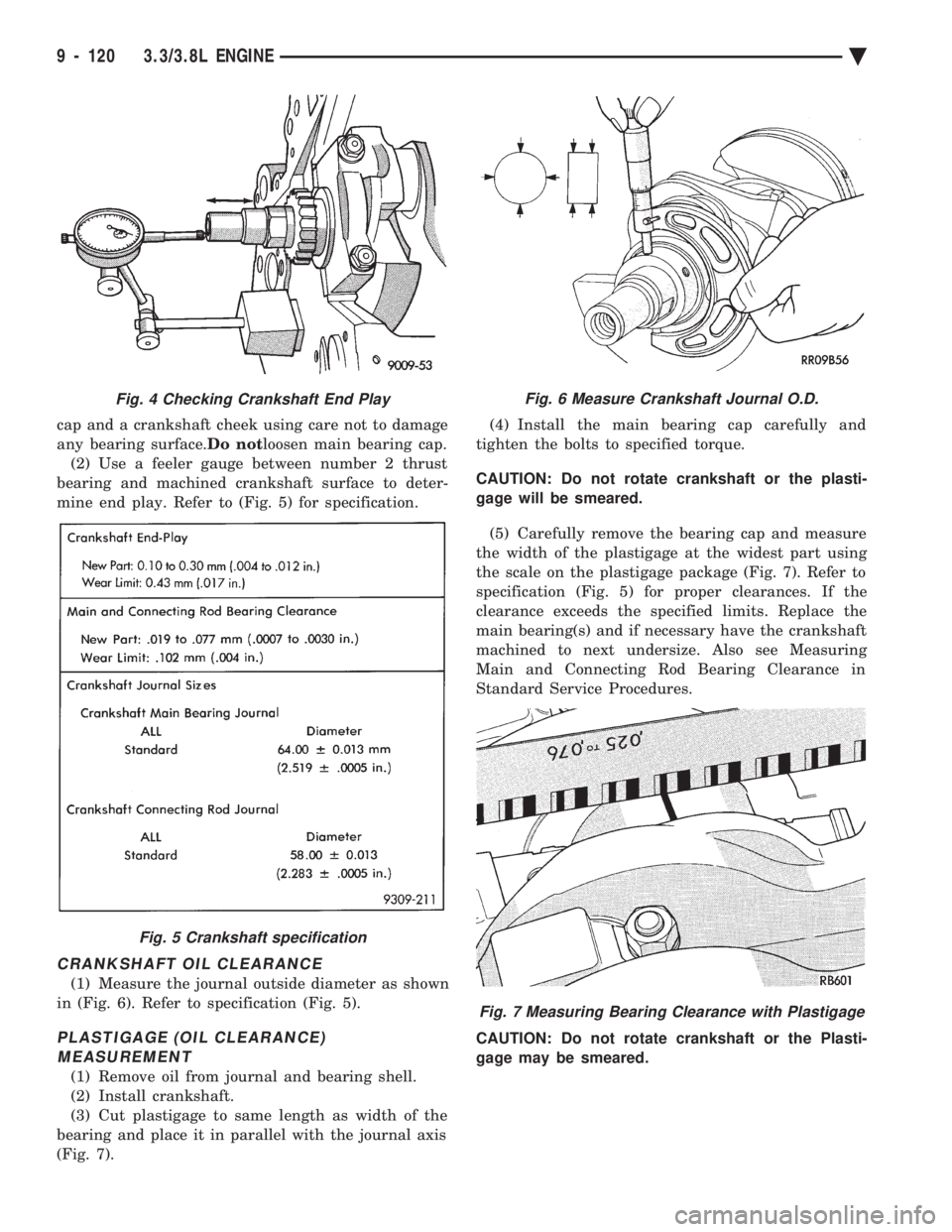
(1) Mount a dial indicator to front of engine, locat-
ing probe on nose of crankshaft (Fig. 4). (2) Move crankshaft all the way to the rear of its
travel. (3) Zero the dial indicator.
(4) Move crankshaft all the way to the front and
read the dial indicator. Refer to (Fig. 5) for specifica-
tion.
CRANKSHAFT END PLAY CHECKÐOPTIONAL
(1) Move crankshaft all the way to the rear of its
travel using a lever inserted between a main bearing
Fig. 3 Removing and Installing Upper Main Bearing With Special Tool C-3059Fig. 1 Main Bearing Cap Identification
Fig. 2 Main Bearing Identification
Ä 3.3/3.8L ENGINE 9 - 119
Page 1686 of 2438
cap and a crankshaft cheek using care not to damage
any bearing surface. Do notloosen main bearing cap.
(2) Use a feeler gauge between number 2 thrust
bearing and machined crankshaft surface to deter-
mine end play. Refer to (Fig. 5) for specification.
CRANKSHAFT OIL CLEARANCE
(1) Measure the journal outside diameter as shown
in (Fig. 6). Refer to specification (Fig. 5).
PLASTIGAGE (OIL CLEARANCE) MEASUREMENT
(1) Remove oil from journal and bearing shell.
(2) Install crankshaft.
(3) Cut plastigage to same length as width of the
bearing and place it in parallel with the journal axis
(Fig. 7). (4) Install the main bearing cap carefully and
tighten the bolts to specified torque.
CAUTION: Do not rotate crankshaft or the plasti-
gage will be smeared.
(5) Carefully remove the bearing cap and measure
the width of the plastigage at the widest part using
the scale on the plastigage package (Fig. 7). Refer to
specification (Fig. 5) for proper clearances. If the
clearance exceeds the specified limits. Replace the
main bearing(s) and if necessary have the crankshaft
machined to next undersize. Also see Measuring
Main and Connecting Rod Bearing Clearance in
Standard Service Procedures.
CAUTION: Do not rotate crankshaft or the Plasti-
gage may be smeared.
Fig. 4 Checking Crankshaft End Play
Fig. 5 Crankshaft specification
Fig. 6 Measure Crankshaft Journal O.D.
Fig. 7 Measuring Bearing Clearance with Plastigage
9 - 120 3.3/3.8L ENGINE Ä
Page 1687 of 2438
CRANKSHAFT OIL SEALS SERVICE
REMOVAL
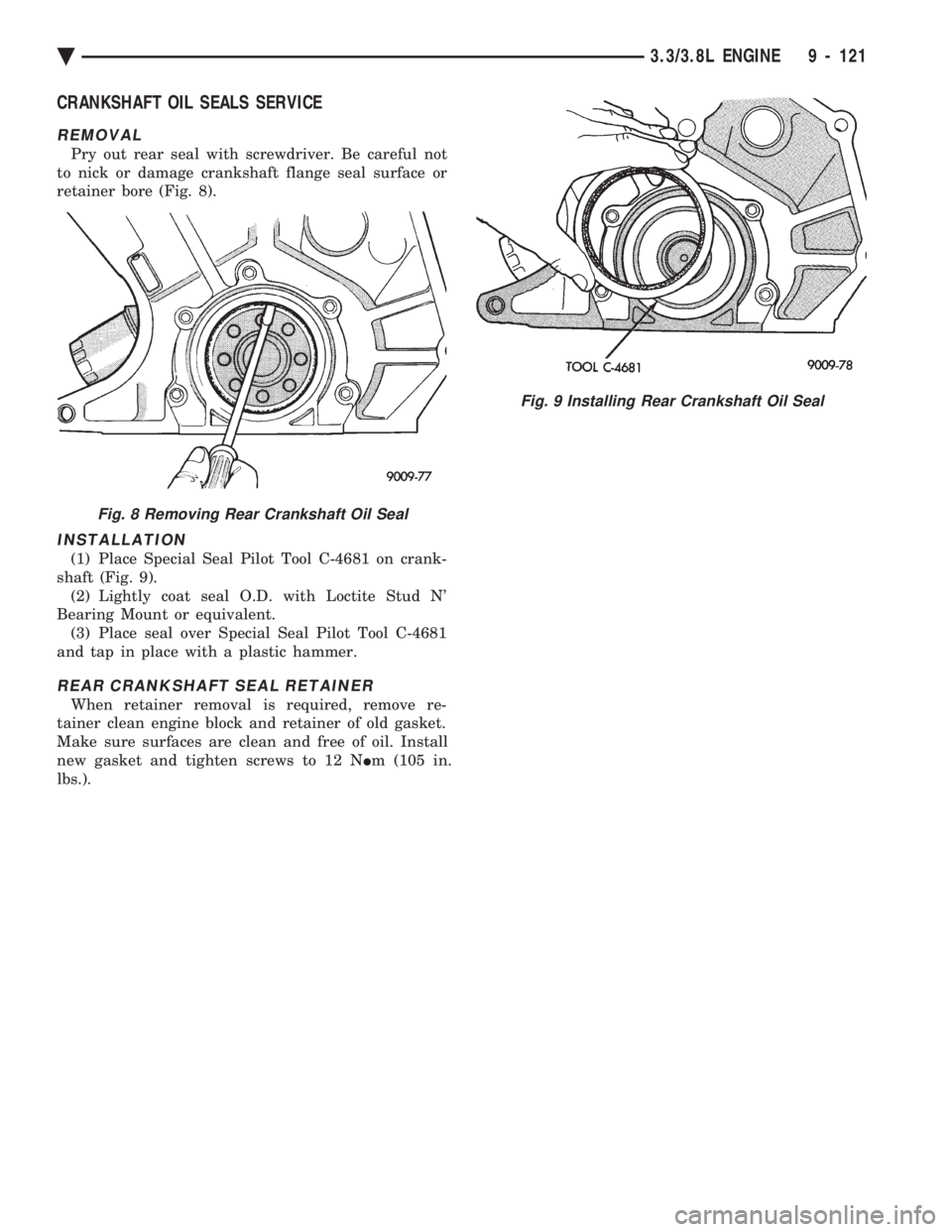
Pry out rear seal with screwdriver. Be careful not
to nick or damage crankshaft flange seal surface or
retainer bore (Fig. 8).
INSTALLATION
(1) Place Special Seal Pilot Tool C-4681 on crank-
shaft (Fig. 9). (2) Lightly coat seal O.D. with Loctite Stud N'
Bearing Mount or equivalent. (3) Place seal over Special Seal Pilot Tool C-4681
and tap in place with a plastic hammer.
REAR CRANKSHAFT SEAL RETAINER
When retainer removal is required, remove re-
tainer clean engine block and retainer of old gasket.
Make sure surfaces are clean and free of oil. Install
new gasket and tighten screws to 12 N Im (105 in.
lbs.).
Fig. 9 Installing Rear Crankshaft Oil Seal
Fig. 8 Removing Rear Crankshaft Oil Seal
Ä 3.3/3.8L ENGINE 9 - 121